Note: Descriptions are shown in the official language in which they were submitted.
STACKING RING FOR CHAIR BASES
CROSS-REFERENCE TO RELATED APPLICATION
100011 This application claims priority to the following U.S.
Provisional Patent
Applications: U.S. Application No. 61/838,089 filed June 21, 2013, titled,
"STACIUNG
RING FOR CHAIR BASES"; and U.S. Serial No. 62/004,351 filed May 29, 2014,
titled,
"STACIUNG RING FOR CHAIR BASES."
BACKGROUND
Field of the Invention
100021 The invention generally relates to features on a chair that
allow certain
shipping configurations.
Description of the Related Art
100031 The bases of chairs ("chair bases") are often made from a
plastic or metal
material, and are frequently manufactured in one location and shipped to a
second location to
be assembled with the other parts of the chair. The chair bases must arrive to
the assembly
location in a presentable condition and not be damaged in transport. Chair
bases that have
been damaged may not be used in the assembly process and are often discarded
as unusable.
Therefore, it is important for the chair bases to be transported in a
sufficiently safe and stable
environment that prevents damage.
100041 Chair bases often have multiple arms that extend from a
central location,
with many chair bases having five extending arms. The arms often extend
radially outward
from the central location, but also angle downward. This configuration is also
aesthetically
pleasing to the user.
100051 In the past, in order to protect the chair base during
shipping, companies
typically put a single chair base in a single box. Shipping chair bases in a
box is
advantageous because it takes an unusually shaped object and hides it in a
rectangular box
that can be easily stacked. These boxes are often stacked on pallets and
shipped via trucks.
Boxes also offer a measure of protection to the chair bases because they are
relatively stable
and rarely shift to a point where the boxes fall over. However, this method of
shipping chair
bases has at least three distinct disadvantages. First, there is a lot of
empty space within a
-1-
Date Recue/Date Received 2020-10-21
box that is not being taken up by its contents. In this case, the unusual
shape of the chair
base, which often includes 5 arms, is very different from the rectangular box
leaving unused
space. Second, the boxes add extra weight to the shipment. The shipper is only
concerned
about shipping the chair bases and only ships the boxes as a means for
protecting the chair
bases. Finally, the boxes add unnecessary waste. After the chair bases arrive
at their target
destination the boxes are either discarded or recycled. The boxes add
unnecessary waste to
the local landfill or at the very minimum, add extra cost to the shipment.
100061 Thus, there is a need for a method of shipping chair bases
that adequately
protects the bases from surface and structural wear, but that also does not
add unnecessary
cost and weight to the process.
SUMMARY
100071 The systems, methods and devices described herein have
innovative
aspects, no single one of which is indispensable or solely responsible for
their desirable
attributes. Without limiting the scope of the claims, some of the advantageous
features will
now be summarized.
100081 In various embodiments, a chair base may be modified to
facilitate a new
and improved shipping configuration such that there is a reduced or no need
for cardboard or
cardboard boxes. In some embodiments, a chair base comprises a hub and a
plurality of
arms extending at least radially from the hub. The hub may be generally
cylindrical or
frustoconical shaped. The top of the hub may comprise an orifice and may be
configured to
accept a component of the chair, such as a vertical shaft that is attached to
the seat portion.
The bottom of the hub of the chair base may comprise a ring and be configured
such that at
least part of the ring of a first chair base may be disposed within at least
part of the top of the
hub of a second chair base.
100091 In some embodiments, the bottom of the hub of the second
chair base may
be disposed within at least part of the top of the hub of a third chair base.
This system may
be continued until a sufficient number of chair bases have been engaged. A
plurality of chair
bases may be serially stacked such that the hub of a first chair base engages
the hub of a
second chair base. The chair bases within the stack may be arranged such that
the arms of
the first chair base are generally lined up with the arms of the second chair
base. Plastic
-2-
Date Recue/Date Received 2020-10-21
wrap or other flexible material, may be wrapped around the top of an arm of
the first chair
base and down around the bottom of an arm of the last chair base, such that
the plastic wrap
encloses at least part of all of the arms of the stack that are generally in
line with each other.
The result may be a chair base stack that is movable as a unit and comprises
two or more
chair bases whose arms are generally in line with each other.
100101 In some embodiments, a chair base stack may be disposed
generally
horizontally on a pallet such that the line from the hub of the first chair
base to the hub of the
last chair base is generally horizontal. A second chair base stack may be
disposed on the
same pallet in generally the same orientation. Stacking of the chair base
stacks may continue
with additional chair base stacks being added to the pallet in a generally
vertical direction
with at least part of each chair base stack being disposed over at least part
of the pallet. The
chair base stacks may be disposed in such a configuration that at least part
of a set of arms of
a first chair base stack are disposed in the space between a set of arms of a
second chair base
stack. The process may continue until the chair base stacks on the pallet
reach a desired
height.
100111 In some embodiments, a chair base stack may be disposed
generally
vertical on a pallet such that the line from the hub of the first chair base
to the hub of the last
chair base is generally vertical. A second chair base stack may be disposed on
the same
pallet in generally the same orientation. Stacking of the chair base stacks
may continue until
the pallet is sufficiently full, resulting in a first layer of chair base
stacks. A second layer of
chair base stacks may be created by disposing a chair base stack on top of the
first layer of
chair base stacks, already disposed on the pallet. This stacking may be
continued until there
is no more room on top of the first layer. Additional layers may be added as
desired.
Additionally, a separator may be placed between the first and second layers of
chair base
stacks.
100121 In some embodiments, a stack of chair base stacks, which are
disposed on
a single pallet, may be wrapped in plastic wrap or other flexible material
such that the plastic
wrap keeps the chair base stacks from shifting during movement of the pallet.
The pallet
containing the chair base stacks may be loaded on to a truck or other mode of
transportation
and shipped to a second location.
-3-
Date Recue/Date Received 2020-10-21
100131
In some embodiments, a stacking ring, separate from the chair base may
be disposable between at least two chair bases, such that the two chair bases
may not move
substantially laterally from one another. The stacking ring may be generally
cylindrical or
frustoconical shaped and may have a plurality of sections that allow disposal
into or around
one or more parts of the chair bases. The stacking ring may comprise a top
portion
configured to insert into a first chair base, a bottom portion configured to
insert into a second
chair base, and a middle portion that may be configured to prevent the
stacking ring from
disposed too far into the first or second chair base. The stacking ring may
comprise a piece
configured to prevent the first chair base from substantially rotating
relative to the second
chair base. Or, the portions may be configured to go around part of a chair
base to generally
serve the same or similar function.
100141
In one aspect, there is provided a method for stacking chair bases where the
method comprises:
positioning a first chair base adjacent a second chair base, wherein the first
chair base and the second chair base are separate chair bases to be stacked
upon one
another, and wherein each chair base comprises:
a cylindrical hub; and
a plurality of legs extending radially from the hub;
the hub, comprising:
a top end with a top planar surface and an inner diameter;
a bottom end with a bottom planar surface and an inner diameter, and
wherein the bottom end is configured to be disposable within at least a part
of the
inner diameter of the top end of a separate chair base; and
an orifice extending axially through the hub and configured to receive a
vertical tube of the chair, the orifice being frustoconical such that the hub
top end
inner diameter is greater than the hub bottom end inner diameter;
the hub bottom end further comprising:
an annular ridge disposed horizontally on the bottom surface; and
an annular ring extending axially and downwardly away from the
ridge, the ring having an outer diameter less than the hub top end
inner diameter;
-4-
Date Recue/Date Received 2020-10-21
aligning the first chair base hub coaxially with the second chair base hub,
such that the bottom end of the first chair base hub is over the top end of
the
second chair base hub;
engaging the bottom end of the first chair base hub with the top end of the
second chair base hub in order to couple the first chair base to the second
chair
base, such that the annular ring of the bottom end of the first chair base hub
is
disposed within at least a part of the inner diameter of the top end of the
second
chair base hub, the outer diameter of the first chair base ring engaging the
inner
diameter of the top end of the second chair base to prevent lateral
displacement
of the first chair base relative to the second chair base;
limiting the axial engagement of the first chair base with the second chair
base in that the annular ridge of the first chair base abuts the top end of
the
second chair base hub; and
restricting rotation of the legs of the first and second chair bases about the
axis of the hubs.
100151 In another aspect, there is provided a method for stacking chair bases,
where
the method comprises:
positioning a first chair base adjacent a second chair base, wherein the first
chair base and the second chair base are separate chair bases to be stacked
upon one
another, and wherein each chair base comprises:
a cylindrical hub; and
a plurality of legs extending radially from the hub;
the hub, comprising:
a top end with a top planar surface and an inner diameter;
a bottom end with a bottom planar surface and an inner diameter; and
an orifice extending axially through the hub;
the hub bottom end further comprising:
an annular ridge disposed horizontally on the bottom surface; and
an annular ring coupled to the ridge, the ring having an outer diameter
less than the hub bottom end inner diameter;
-5-
Date Recue/Date Received 2020-10-21
aligning the first chair base hub coaxially with the second chair base hub,
such that the bottom end of the first chair base hub is over the top end of
the
second chair base hub;
engaging the bottom end of the first chair base hub with the top end of the
second chair base hub in order to couple the first chair base to the second
chair
base, such that the annular ring of the bottom end of the first chair base hub
is
disposed within at least a part of the inner diameter of the top end of the
second
chair base hub, the outer diameter of the first chair base ring engaging the
inner
diameter of the top end of the second chair base to prevent lateral
displacement
of the first chair base relative to the second chair base;
causing the annular ridge of the first chair base to abut the hub of the
second chair base to limit the axial engagement of the first chair base with
the
second chair base.
100161
In yet another aspect there is provided a method for stacking chair bases
which
comprises:
positioning a first chair base adjacent a second chair base, wherein the first
chair base and the second chair base are separate chair bases to be stacked
upon one
another, and wherein each chair base comprises:
a hub; and
a plurality of legs extending radially from the hub;
the hub, comprising:
a top end with a top planar surface and an inner diameter; and
a bottom end with a bottom planar surface and an inner diameter, and
wherein the bottom end is configured to be disposable within at least a part
of the
inner diameter of the top end of a separate chair base;
the bottom end further comprising:
an annular ridge disposed on the bottom planar surface; and
an annular ring extending axially and downwardly away from the
annular ridge, the annular ring having an outer diameter less than the
inner diameter of the top end; and
-6-
Date Recue/Date Received 2020-10-21
engaging the bottom end of a first chair base hub with the top end of a
second chair base hub in order to couple the first chair base to the second
chair
base, such that the annular ring of the bottom end of the first chair base hub
is
disposed within at least a part of the inner diameter of the top end of the
second
chair base hub, the outer diameter of the first chair base ring engaging the
inner
diameter of the top end of the second chair base to prevent lateral
displacement
of the first chair base relative to the second chair base.
100171 In still another aspect there is provided a chair base system for
stacking.
The chair base system comprises a first chair base, wherein the first chair
base comprises: a
hub; and a plurality of legs extending radially from the hub. The hub of the
first chair base
comprises: a top end with a top surface and an inner diameter; and a bottom
end with a
bottom surface and an inner diameter. The bottom end of the first chair base
further
comprises: an annular transition portion disposed on the bottom surface; and
an annular ring
coupled to the annular transition portion, where the annular ring has an outer
diameter less
than the inner diameter of the bottom end of the hub. A second chair base is
provided, where
the second chair base comprises: a hub; and a plurality of legs extending
radially from the
hub. The hub of the second chair base comprises: a top end with a top surface
and an inner
diameter; and a bottom end with a bottom surface and an inner diameter. The
bottom end of
the second chair base further comprises: an annular transition portion
disposed on the bottom
surface; and an annular ring coupled to the annular transition portion, the
annular ring having
an outer diameter less than the inner diameter of the bottom end of the hub.
The bottom end
of the first chair base hub is configured to engage with the top end of the
second chair base
hub in order to couple the first chair base to the second chair base, such
that the annular ring
of the bottom end of the first chair base hub is disposed within at least a
part of the inner
diameter of the top end of the second chair base hub, the outer diameter of
the first chair
base ring engaging the inner diameter of the top end of the second chair base
to prevent
lateral displacement of the first chair base relative to the second chair
base.
100181 In another aspect, there is provided a set of stacking chair bases
comprising:
a first chair base and a second chair base adjacent to the first chair base,
where the first chair
base and the second chair base are separate chair bases to be stacked upon one
another. Each
chair base comprises: a hub; and a plurality of legs extending radially from
the hub; where
-7-
Date Recue/Date Received 2020-10-21
the hub, comprises: a top end with a top planar surface and an inner diameter;
and a bottom
end with a bottom planar surface and an inner diameter, and wherein the bottom
end is
configured to be disposable within at least a part of the inner diameter of
the top end of a
separate chair base. The bottom end further comprises: an annular ridge
disposed on the
bottom planar surface; and an annular ring extending axially and downwardly
away from the
annular ridge, where the annular ring has an outer diameter less than the
inner diameter of
the top end. The bottom end of a first chair base hub is engagable with the
top end of a
second chair base hub in order to couple the first chair base to the second
chair base, such
that the annular ring of the bottom end of the first chair base hub is
disposed within at least a
part of the inner diameter of the top end of the second chair base hub, and
the outer diameter
of the first chair base ring engages the inner diameter of the top end of the
second chair base
to prevent lateral displacement of the first chair base relative to the second
chair base.
100191 In another aspect, there is provided a method for stacking chair bases
where
the method comprises:
positioning a first chair base adjacent a second chair base, wherein the first
chair base and the second chair base are separate chair bases to be stacked
upon one
another, and wherein each chair base comprises:
a hub from which a plurality of legs extend, the hub comprising:
a first end with a first planar surface and an inner diameter; and
a second end with a second planar surface and a second inner diameter,
and wherein the second end is configured to be disposable within at least a
part
of the inner diameter of the first end of a separate chair base;
the second end further comprising:
an annular ring extending axially and downwardly away from the
second planar surface, the annular ring having an outer diameter less
than the inner diameter of the first end; and
engaging the second end of a first chair base hub with the first end of a
second chair base hub in order to couple the first chair base to the second
chair
base, such that the annular ring of the second end of the first chair base hub
is
disposed within at least a part of the inner diameter of the first end of the
second
-8-
Date Recue/Date Received 2020-10-21
chair base hub, the outer diameter of the second end of the first chair base
ring
engaging the inner diameter of the first end of the second chair base.
100201
In yet another aspect, there is provided a chair base system for stacking
which
comprises:
a first chair base, wherein the first chair base comprises:
a hub from which a plurality of legs extend, the hub comprising:
a first end with a first surface and an inner diameter; and
a second end with a second surface and an inner diameter;
the second end further comprising:
an annular ring coupled to the second surface, the annular ring having
an outer diameter less than the inner diameter of the second end of the
hub, and
a second chair base, wherein the second chair base comprises:
a hub from which a plurality of legs extend, the hub comprising:
a first end with a first surface and an inner diameter; and
a second end with a second surface and an inner diameter;
the second end further comprising:
an annular ring coupled to the second surface, the annular ring having
an outer diameter less than the inner diameter of the second end of the
hub,
wherein the second end of the first chair base hub is configured to engage
with the first end of the second chair base hub in order to couple the first
chair
base to the second chair base, such that the annular ring of the second end of
the
first chair base hub is disposed within at least a part of the inner diameter
of the
first end of the second chair base hub.
100211
In still yet another aspect, there is provided a set of stacking chair bases
which comprises: a first chair base and a second chair base adjacent to the
first chair base,
wherein the first chair base and the second chair base are separate chair
bases to be stacked
upon one another. Each chair base comprises: a hub from which a plurality of
legs extend,
the hub comprising: a first end with a first planar surface and an inner
diameter; and a second
end with a second planar surface and an inner diameter, and where the second
end is
-9-
Date Recue/Date Received 2020-10-21
configured to be disposable within at least a part of the inner diameter of
the first end of a
separate chair base. The second end further comprises: an annular ring
extending axially and
downwardly away from the second planar surface, where the annular ring has an
outer
diameter less than the inner diameter of the first end. The second end of a
first chair base
hub is engaged with the first end of a second chair base hub in order to
couple the first chair
base to the second chair base, such that the annular ring of the second end of
the first chair
base hub is disposed within at least a part of the inner diameter of the first
end of the second
chair base hub.
100221 In another aspect, there is provided a chair base system for stacking,
the chair base
system comprising:
a first chair base, wherein the first chair base comprises:
a hub from which a plurality of legs extend, the hub comprising:
a first end with a first surface and an inner diameter; and
a second end with a second surface and an inner diameter; and
a second chair base, wherein the second chair base comprises:
a hub from which a plurality of legs extend, the hub comprising:
a first end with a first surface and an inner diameter; and
a second end with a second surface and an inner diameter;
the second end further comprising:
an annular ring comprising a generally annular shape
and including a first diameter of a first portion of the annular
ring and a second diameter of a second portion of the annular
ring,
wherein the second end of the first chair base hub is configured to engage
with the first end of the second chair base hub in order to couple the first
chair base
to the second chair base, such that the annular ring of the second end of the
first chair
base hub is disposed within at least a part of the inner diameter of the first
end of the
second chair base hub.
100231
In yet another aspect, there is provided an annular ring for stacking chair
bases. The annular ring comprises: a generally annular shape and including a
first diameter
of a first portion of the annular ring and a second diameter of a second
portion of the annular
- 1 0-
Date Recue/Date Received 2020-10-21
ring where a second end of a first chair base hub is configured to engage with
a first end of a
second chair base hub in order to couple the first chair base to the second
chair base, such
that the annular ring of the second end of the first chair base hub is
disposed within at least a
part of an inner diameter of the first end of the second chair base hub. The
first chair base
comprises: a hub from which a plurality of legs extend, where the hub
comprises: a first end
with a first surface and an inner diameter; and the second end with a second
surface and an
inner diameter. The second chair base comprises: a hub from which a plurality
of legs
extend, the hub comprising: the first end with a first surface and the inner
diameter; and a
second end with a second surface and an inner diameter.
100241 In another aspect, there is provided a method for stacking chair bases,
the method
comprising:
engaging a second end of a hub of a first chair base with a first end of a hub
of a second chair base in order to couple the first chair base to the second
chair base,
such that an annular ring of the second end of the first chair base hub is
disposed
within at least a part of the inner diameter of the first end of the second
chair base
hub,
wherein the first chair base comprises:
the hub from which a plurality of legs extend, the hub comprising:
a first end with a first surface and an inner diameter; and
the second end with a second surface and an inner diameter;
and
wherein the second chair base comprises:
the hub from which a plurality of legs extend, the hub comprising:
the first end with a first surface and an inner diameter; and
a second end with a second surface and an inner diameter;
the second end further comprising:
the annular ring comprising a generally annular shape
and including a first diameter of a first portion of the annular
ring and a second diameter of a second portion of the annular
ring.
- 1 1 -
Date Recue/Date Received 2020-10-21
BRIEF DESCRIPTION OF THE DRAWINGS
100251 The above-mentioned aspects, as well as other features,
aspects, and
advantages of the present technology will now be described in connection with
various
embodiments, with reference to the accompanying drawings. The illustrated
embodiments,
however, are merely examples and are not intended to be limiting. Like
reference numbers
and designations in the various drawings indicate like elements. Not all of
the elements of
the drawings are in to scale relate to other drawings and the comparative size
of one element
relative to another element in the drawings is not necessarily indicative of
the relative sizes
of the elements in one or more embodiments.
100261 Figure 1 is a bottom perspective view of a chair base.
100271 Figure 2 is a side view of a plurality of chair bases stacked
together.
100281 Figure 3 illustrates a perspective view of a first embodiment
of a stacking
ring for chair bases.
100291 Figure 4 illustrates a side view of the first embodiment of a
stacking ring
for chair bases.
100301 Figure 5 illustrates a sectional view of the first embodiment
of a stacking
ring for chair bases.
100311 Figure 6 illustrates a perspective view of a second
embodiment of a
stacking ring for chair bases.
100321 Figure 7 is a side view of a plurality of chair bases stacked
together on a
shipping pallet.
100331 Figure 8 is a side view of a plurality of chair bases stacked
together on a
shipping pallet and wrapped in plastic wrap.
DETAILED DESCRIPTION
100341 In the following detailed description, reference is made to
the
accompanying drawings, which form a part of the present disclosure. The
illustrative
embodiments described in the detailed description, drawings, and claims are
not meant to be
limiting. Other embodiments may be utilized, and other changes may be made,
without
departing from the spirit or scope of the subject matter presented here. It
will be readily
understood that the aspects of the present disclosure, as generally described
herein, and
-12-
Date Recue/Date Received 2020-10-21
illustrated in the Figures, can be arranged, substituted, combined, and
designed in a wide
variety of different configurations, all of which are explicitly contemplated
and form part of
this disclosure. For example, a system or device may be implemented or a
method may be
practiced using any number of the aspects set forth herein. In addition, such
a system or
device may be implemented or such a method may be practiced using other
structure,
functionality, or structure and functionality in addition to or other than one
or more of the
aspects set forth herein. Elements that are described as "connected,"
"engaged," "attached,"
or similarly described, shall include being directly and/or indirectly
connected, engaged,
attached, etc. Alterations and further modifications of the inventive features
illustrated
herein, and additional applications of the principles of the inventions as
illustrated herein,
which would occur to one skilled in the art and having possession of this
disclosure, are to be
considered within the scope of the invention.
100351 Descriptions of unnecessary parts or elements may be omitted
for clarity
and conciseness, and like reference numerals refer to like elements
throughout. In the
drawings, the size and thickness of layers and regions may be exaggerated for
clarity and
convenience.
100361 Features of the present disclosure will become more fully
apparent from
the following description and appended claims, taken in conjunction with the
accompanying
drawings. It will be understood these drawings depict only certain embodiments
in
accordance with the disclosure and, therefore, are not to be considered
limiting of its scope;
the disclosure will be described with additional specificity and detail
through use of the
accompanying drawings. An apparatus, system or method according to some of the
described embodiments can have several aspects, no single one of which
necessarily is solely
responsible for the desirable attributes of the apparatus, system or method.
After considering
this discussion, and particularly after reading the section entitled "Detailed
Description" one
will understand how illustrated features serve to explain certain principles
of the present
disclosure.
100371 In some embodiments, a chair base 100 may comprise a hub 102
and a
plurality of arms 104, as shown in Figs. 1 and 2. Portions of the hub 102 may
be generally
cylindrical or frustoconical shaped. The center of the hub 102 may comprise an
orifice 106
in order to accept other portions of the chair assembly; or, the hub 102 may
comprise other
-13-
Date Recue/Date Received 2020-10-21
structures. A plurality of arms 104 may extend from the hub 102. The arms 104
may extend
radially and to some degree in a downward direction, as depicted in Fig. 2.
The outward
ends of the arms 104 may be configured to accept a foot or a caster that will
eventually rest
on the ground once the chair is more fully assembled.
100381 The hub 102 may be several inches in diameter and several
inches in
height. In some embodiments, the outside diameter of the hub 102 is between 1
and 8
inches; in some embodiments, the outside diameter of the hub 102 is between
approximately
3 and 4 inches. In some embodiments, the height of the hub 102 is between
approximately 2
and 8 inches. The arms 104 may be several inches long and may be long enough
to
adequately support a user once the chair is more fully assembled. The chair
base 100 may be
made from plastic, metal, or other generally durable material. The base 100
may be formed
by various manufacturing means, including injection molding, casting,
machining, press-
fitting, etc. The hub 102 and arms 104 may be integrally formed, or may be
made separately
and later assembled.
100391 As shown in Fig. 1, the bottom of the hub 102 may comprise a
ring 110.
The ring 110 on the bottom of a first chair base 100 may be placed in the top
of the hub 102
of a second chair base 100. Additional chair bases 100 may be added such that
a plurality of
chair bases 100 becomes stacked in a series, as shown in Fig. 2. The ring 110
may be
integrally formed with the hub 102, or may be added after the hub 102 has
already been
formed. The ring 110 may be generally cylindrical or frustoconical shaped with
generally
vertical walls. The bottom surface of the ring 112 may be generally flat or
may comprise
another shape. The inside of the hub 102 may comprise a shape that is at least
partially
conducive to reception of another chair part, such as a vertical tube (not
shown) that extends
up to the chair's seat portion. The ring 110 of a first hub 102 may be formed
such that when
the ring 110 is placed in the top of a second hub 102, the ring 110
substantially prevents the
first hub 102 from being displaced laterally relative to the second hub 102.
In some
embodiments, the ring 110 is formed such that two engaged hubs 102 require
little force to
become disengaged. In another embodiment, the ring 110 is formed such that the
two
engaged hubs 102 require some force to become disengaged. The bottom of the
hub 102
may be formed such that there is a substantially horizontal portion adjacent
the ring 110; or
the portion next to the ring 110 may be angled or slanted. The portion 113
adjacent the ring
-14-
Date Recue/Date Received 2020-10-21
110, may be configured to abut the second hub 1032 and may prevent the first
hub 102 from
being disposed too far into the second hub 102. The hub 102, arms 104, and
ring 110 may
be integrally formed, or may be made separately and later assembled.
100401
In some embodiments, the bottom of the hub 102 is flat or comprises no
ring 110 feature. Instead, as shown in Figures 3-5, in some embodiments, the
stacking ring
200 comprises a generally annular shape, comprising a top portion 205, a
middle portion
210, and a bottom portion 215, and may be separate from the chair base. The
top portion
205, the middle portion 210, and the bottom portion 215 may be disposed
generally coaxial
to one another. The top portion 205 may comprise an annular ring comprising a
wall
thickness 400, an inside diameter, and an outside diameter 405. The top
portion 205 may be
adjacent the middle portion 210. The middle portion 210 may comprise an
annular ring
comprising an inside diameter and an outside diameter. The middle portion 210
may be
adjacent the bottom portion 215. The bottom portion 215 may comprise an
annular ring
comprising a wall thickness, an inside diameter, and an outside diameter 415.
The top
portion 205 may further comprise a height 305; the middle portion 210 may
further comprise
a height 310; and the bottom portion 215 may further comprise a height 315. In
some
embodiments, the height 305 of the top portion 205 and the height 315 of the
bottom portion
215 may be the same or similar, and may be larger than a height 310 of the
middle portion
210. In some embodiments, the outside diameter 405 of the top portion 205 may
be smaller
than the outside diameter 415 of the bottom portion 215, which may be smaller
than the
outside diameter of the middle portion 210. In some embodiments, the inside
diameter of
the top portion 205 is the same or similar to the inside diameter of the
middle portion 210,
which may be smaller than the inside diameter of the bottom portion 215. In
some
embodiments, the wall thickness 400 of the top portion 205 may be the same or
similar to the
wall thickness of the bottom portion 215. In some embodiments, the stacking
ring 200
defines a hole or aperture 220 that goes substantially or all the way through
the stacking ring
200. In some embodiments (not shown), the stacking ring 200 does not define a
hole or
aperture 220. The exact dimensions of the stacking ring 200 may be influenced,
at least in
part, by the chair bases to which the stacking ring 200 is to be attached, and
the scope of the
invention is not limited by the absolute or relative sizes of any portions of
the stacking ring.
-15-
Date Recue/Date Received 2020-10-21
[0041] In some embodiments, the top portion 205, middle portion 210,
and
bottom portion 215 may be integrally formed, or may be produced in parts and
later
assembled. The stacking ring 200 may comprise a material such as plastic,
nylon, metal,
wood, or other material that may adequately form the desired structure. The
stacking ring
200 may be produced through casting, machining, forging, or other various
production
methods.
[0042] A first stacking ring 200 may be used by being placed in
between a first
chair base 100 and a second chair base 100 such that the first stacking ring
200 is generally
coaxial with a hub 102 of the first chair base 100 and a hub 102 of the second
chair base 100.
A second stacking ring 200 may be placed between a hub 102 of the second chair
base 100
and a hub 102 of a third chair base 100. Additional stacking rings 200 and
chair bases 100
may be similarly configured. In some embodiments, the top portion 205 of a
stacking ring
200 may be configured to be disposed or disposable within an opening 106 of a
hub 102 of a
chair base 100. For instance, the outside diameter 405 of the top portion 205
may be the
same size as, or smaller than, and inside diameter of a bottom portion of a
chair base hub.
The outside diameter 415 of a bottom portion 215 of a stacking ring 200 may be
the same
size as, or smaller than, and inside diameter of a top portion of a chair base
hub 102. In
these configurations, the top portion 205 may be disposed within at least part
of the bottom
portion of the chair base hub 102; and the bottom portion 215 may be disposed
within at
least part of the top portion of the chair base hub 102.
[0043] In some embodiments, using a stacking ring 200 that is
disposable
between two or more chair base hubs 202 may be advantageous. For instance, as
a non-
limiting example, there may be no need, or minimal need, to redesign the molds
used to
create chair bases. The stacking rings 200 may be configured to fit in or
between a wide
variety of chair bases, or multiple sizes of stacking rings 200 may be
produced that can fit
between different sized chair base hubs. Stacking rings 200 may be
manufactured by a third-
party and purchased by a chair base manufacturer, alleviating the need for the
chair base
manufacturer to produce a part necessary for serially assembling chair base
hubs for
transport. The stacking rings 200 may be configured to be reusable, and may be
recovered
after the chair bases have reached their destination for assembly. The
stacking rings 200
-16-
Date Recue/Date Received 2020-10-21
may be gathered and returned to the chair base manufacturer for use in
transport with a
second batch of chair bases.
100441 In some embodiments, an outside diameter 405 of the top
portion 205 may
be between 1.5 inches and 2 inches, or may be approximately 1.75 inches. A
height 305 of
the top portion 205 may be between approximately 0.1 inches and 2 inches, or
may be
approximately 0.25 inches. An outside diameter 315 of the bottom portion 115
may be
between approximately 1.75 inches and 2.25 inches, or may be approximately 2
inches. A
height 215 of the bottom portion 115 may be between approximately 0.1 inches
and 2 inches,
or may be approximately 0.25 inches. A height 310 of the middle portion 210
may be
between approximately 0.01 inches and 0.5 inches, or may be approximately 0.06
inches. In
some embodiments, the heights and diameters of the portions of the stacking
ring 200 may
be sized to be disposable within at least part of a hub 102 of a chair base
100, and therefore
may be larger or smaller than the given dimensions, depending on the
dimensions of the
chair base 100. For instance, as a non-limiting example, if an inside diameter
of a chair base
100 is 3 inches, one or more of the outside diameters 405, 415 of a stacking
ring 200 may be
approximately 3 inches or less. The heights of the portions of a stacking ring
200 may also
be configured to fit within the various sized chair bases 200, and may deviate
from the
dimensions given, depending on the dimensions of the chair base 100. For
instance, as a
non-limiting example, it may be advantageous for the middle portion 210 to be
1 inch in
height or more, depending on the configuration of the chair base 100. The
dimensions of the
stacking ring 200 may be scalable for various applications, and the scope of
the invention is
not limited by the exact dimensions of the stacking ring 200. Various
dimensions of the
stacking ring 200 may be larger or smaller than those given without deviating
from the scope
of the invention.
100451 In some embodiments the stacking ring 200 may comprise a
feature to
help prevent or discourage a first chair base 100 from rotating axially
relative to a second
chair base 100. Since the chair bases 100 may be secured to one another using
at least plastic
wrap or other material, the chair bases 100 may have a tendency to rotate
relative to one
another. It may be beneficial to generally prevent the chair bases 100 from
rotating in order
that the arms 104 of the chair bases 100 generally align, creating a more
efficient interaction
with other stacks of chair bases 100. See, e.g., Fig. 2.
-17-
Date Recue/Date Received 2020-10-21
100461 In some embodiments, the feature 225 may be a protrusion, a
recess, a
male part, a female part, or some other shape or contour that may interact
with a portion of a
chair base 100, such that the stacking ring 200 generally prevents rotational
movement of the
chair base 100. As shown in Fig. 6, the feature may comprise a protrusion 225
that may
interact with a corresponding recess on a chair base 100. When the stacking
ring 200
engages a first chair base 100, the protrusion 225 may engage a recess in the
first chair base
100. Thus, when a rotational force is applied to the first chair base 100, the
force may be at
least partially transmitted to the stacking ring 200 via the protrusion 225,
such that when first
chair base 100 rotates, the stacking ring 200 may generally rotate at the same
rate. In some
embodiments, a recess on a chair base 100 may be disposed only partially
through the chair
base hub 102. In some embodiments, a recess on a chair base 100 may span the
thickness of
the chair base hub 102.
100471 The stacking ring 200 may comprise a first protrusion 225 and
a second
protrusion (not shown). The first protrusion 225 may be disposed on the top of
the stacking
ring 200, while the second protrusion may be disposed on the bottom of the
stacking ring
200. When the stacking ring 200 engages a second chair base 100, the second
protrusion
may engage a recess in the second chair base 100. Thus, when the stacking ring
200 engages
both a first and second chair base 100, and a rotational force is applied to
the first chair base
100, the rotational force may be transmitted to the second chair base 100 via
the stacking
ring 200 and the first 225 and second protrusions. In these configurations,
the first and
second chair bases 100 may generally be prevented or discouraged from rotating
independent
of one another. However, a stacking ring 200 need not completely prevent a
first chair base
100 from rotating independent of a second chair base 100, and the scope of the
invention is
not limited to embodiments where the stacking ring 200 completely prevents the
first chair
base 100 from rotating relative to the second chair base 100.
100481 In some embodiments, the stacking ring 200 comprises a first
and second
recess (not shown) configured to interact with protrusions on a first and
second chair base
100. In some embodiments, the stacking ring 200 may comprise one protrusion
and one
recess that interact with a corresponding recess and protrusion respectively.
In some
embodiments, the stacking ring 200 may comprise a plurality of protrusions
and/or recesses.
The protrusion 225 on a stacking ring 200 may comprise various shapes and
dimensions and
-18-
Date Recue/Date Received 2020-10-21
the scope of the invention is not limited by the shape and dimensions of the
protrusion 225.
For instance, a protrusion 225 on a stacking ring 200 may engage or connect to
the top
portion 205 and the middle portion 210. In some embodiments, the height of the
protrusion
225 is approximately the same height as the top portion 205; or, the
protrusion 225 may be
taller or shorter than the top portion 205. In some embodiments, the
protrusion 225 may
extend radially from the top portion 205 to approximately the edge of the
middle portion
210; or, the protrusion 225 may extend farther than or short of the middle
portion 210. In
some embodiments, the protrusion 225 may contact the top portion 205 and not
contact the
middle portion 210; or the protrusion 225 may contact the middle portion 210
and not
contact the top portion 205. Other configurations may be possible and a person
of ordinary
skill in the art would recognize that the scope of the invention is not
limited to the
configurations described above.
100491
As shown in Fig. 2, once a first hub 102 has been engaged to a second hub
102, additional hubs 102 and chair bases 100 may be engaged. The result may be
a series of
chair bases 114 that are engaged via their hubs. Fig. 2 depicts four chair
bases 100 wherein
the hubs 102 are disposed generally coaxially. Some embodiments comprise a
ring 110 that
has a smaller outer diameter than the hub 102 (shown in Fig. 1). Once multiple
chair bases
100 have been engaged via the stacking ring 110, the stacking ring 110 may not
be visible
from a side profile view of the intersection of a first and second chair base
100 (shown in
Fig. 2). In some embodiments, once the hubs 102 are engaged, but before any
part of the
stack 114 is wrapped in plastic wrap, the chair bases 100 may still be able to
rotate about the
hub 102. The arms 104 of the chair bases 100 may be aligned such that one arm
104 of each
chair base 100 may be wrapped with a plastic wrap or other flexible material.
The second
arms 104 of all chair bases 100 in the stack 114 may then be wrapped with the
same
material. This may be continued until all arms 104 have been wrapped with the
arms 104
above or below it. The result may be a chair base "stack" 114 that can be
moved and
manipulated as a single unit. Since plastic wrap surrounds one set of arms 104
of the chair
base stack 114, the plastic wrap may substantially prevent a first chair base
100 from rotating
independently from a second chair base 100. This chair base stack 114 also
includes a space
between the wrapped arms 104. The plastic wrap may function to keep the
plurality of chair
bases 100 together and prevent them from moving in various directions. The
plastic wrap
-19-
Date Recue/Date Received 2020-10-21
may also help to prevent damage to the surface of the chair bases 100 by
protecting the
surface. The plastic wrap may also help to prevent damage to the chair bases
100 by creating
additional friction between the chair base stacks 114 and substantially
preventing them from
shifting during transport.
100501 Once the chair base stacks 114 have been created, multiple
stacks 114 may
be placed on a shipping pallet 116, in preparation for transportation to a
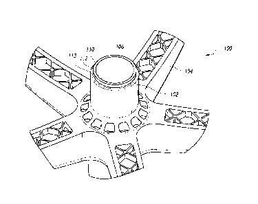
different location.
Fig. 7 shows a plurality of stacks 114 positioned on a pallet 116. In some
embodiments, the
stacks 114 are placed horizontally on a pallet 116. The arms 104 of one stack
114 may be
placed between the arms 104 of a second stack 114. Several stacks 114 may be
placed on a
pallet 116 in a generally vertical fashion. Elongated pieces of wood,
cardboard, or other
structurally sound material 120 may be placed between the stacks 114 during
assembly
and/or during transport. The elongated pieces 120 may help the loading and
unloading
process, or may provide additional structural support or protection to the
chair bases 100.
100511 In some embodiments (not shown), the chair base stacks 114
may be
placed vertically on the pallet 116 to create a first layer of stacks 114.
Subsequent layers of
stacks 114 may be added on top of the first layer of stacks 114. Cardboard or
other similar
material 120 may be inserted between the stacks 114 to help add stability or
damage
resistance.
100521 Once the stacks of chair bases 114 have been assembled onto a
pallet 116,
the pallet 116 may be wrapped with plastic wrap or otherwise secured such that
there is
minimal movement of the chair bases 100 during transport, and loaded onto or
into a
shipping container, as shown in Fig. 8. The plastic wrap may also help to
prevent damages
to the chair bases 100. The plastic wrap may also help prevent dust and debris
from settling
on the chair bases 100 during transport as well as loading, unloading, and
during storage.
100531 The configuration of chair bases 100 and chair base stacks
114 may be
advantageous because it reduces or eliminates the need for excessive cardboard
during the
transportation phase of chair production and assembly. Typically, cardboard
boxes have
been used to protect the chair bases 100 during transport, and create a
uniform shape which
is more conducive to stacking. However, cardboard costs money to purchase and
dispose.
Cardboard also adds unnecessary weight to the shipment. Using a square
cardboard box that
-20-
Date Recue/Date Received 2020-10-21
houses a chair base 100 (which often comprises 5 arms), also creates a lot of
unused space
within the four-sided box.
[0054] Various modifications to the implementations described in
this disclosure
may be readily apparent to those skilled in the art, and the generic
principles defined herein
may be applied to other implementations without departing from the spirit or
scope of this
disclosure. Thus, the claims are not intended to be limited to the
implementations shown
herein, but are to be accorded the widest scope consistent with this
disclosure, the principles
and the novel features disclosed herein. Additionally, a person having
ordinary skill in the
art will readily appreciate, the terms "upper" and "lower" are sometimes used
for ease of
describing the figures, and indicate relative positions corresponding to the
orientation of the
figure on a properly oriented page, and may not reflect the proper orientation
of the device as
implemented.
[0055] Certain features that are described in this specification in
the context of
separate implementations also can be implemented in combination in a single
implementation. Conversely, various features that are described in the context
of a single
implementation also can be implemented in multiple implementations separately
or in any
suitable sub combination. Moreover, although features may be described above
as acting in
certain combinations and even initially claimed as such, one or more features
from a claimed
combination can in some cases be excised from the combination, and the claimed
combination may be directed to a sub combination or variation of a sub
combination.
[0056] Similarly, while operations are depicted in the drawings in a
particular
order, this should not be understood as requiring that such operations be
performed in the
particular order shown or in sequential order, or that all illustrated
operations be performed,
to achieve desirable results. Further, the drawings may schematically depict
one more
example processes in the form of a flow diagram. However, other operations
that are not
depicted can be incorporated in the example processes that are schematically
illustrated.
Additionally, other implementations are within the scope of the following
claims. In some
cases, the actions recited in the claims can be performed in a different order
and still achieve
desirable results.
[0057] In describing the present technology, the following
terminology may have
been used: The singular forms "a," "an," and "the" include plural referents
unless the context
-21-
Date Recue/Date Received 2020-10-21
clearly dictates otherwise. Thus, for example, reference to an item includes
reference to one
or more items. The term "ones" refers to one, two, or more, and generally
applies to the
selection of some or all of a quantity. The term "plurality" refers to two or
more of an item.
The term "about" means quantities, dimensions, sizes, formulations,
parameters, shapes and
other characteristics need not be exact, but may be approximated and/or larger
or smaller, as
desired, reflecting acceptable tolerances, conversion factors, rounding off
measurement
error and the like and other factors known to those of skill in the art. The
term
"substantially" means that the recited characteristic, parameter, or value
need not be achieved
exactly, but that deviations or variations, including for example, tolerances,
measurement
error, measurement accuracy limitations and other factors known to those of
skill in the art,
may occur in amounts that do not preclude the effect the characteristic was
intended to
provide. Numerical data may be expressed or presented herein in a range
format. It is to be
understood that such a range format is used merely for convenience and brevity
and thus
should be interpreted flexibly to include not only the numerical values
explicitly recited as
the limits of the range, but also interpreted to include all of the individual
numerical values
or sub-ranges encompassed within that range as if each numerical value and sub-
range is
explicitly recited.
As an illustration, a numerical range of "about 1 to 5" should be
interpreted to include not only the explicitly recited values of about 1 to
about 5, but also
include individual values and sub-ranges within the indicated range. Thus,
included in this
numerical range are individual values such as 2, 3 and 4 and sub-ranges such
as 1-3, 2-4 and
3-5, etc. This same principle applies to ranges reciting only one numerical
value (e.g.,
"greater than about 1") and should apply regardless of the breadth of the
range or the
characteristics being described. A plurality of items may be presented in a
common list for
convenience. However, these lists should be construed as though each member of
the list is
individually identified as a separate and unique member. Thus, no individual
member of
such list should be construed as a de facto equivalent of any other member of
the same list
solely based on their presentation in a common group without indications to
the contrary.
Furthermore, where the terms "and" and "or" are used in conjunction with a
list of items,
they are to be interpreted broadly, in that any one or more of the listed
items may be used
alone or in combination with other listed items. The term "alternatively"
refers to selection
of one of two or more alternatives, and is not intended to limit the selection
to only those
-22-
Date Recue/Date Received 2020-10-21
listed alternatives or to only one of the listed alternatives at a time,
unless the context clearly
indicates otherwise.
100581 It should be noted that various changes and modifications to
the presently
preferred embodiments described herein will be apparent to those skilled in
the art. Such
changes and modifications may be made without departing from the spirit and
scope of the
invention and without diminishing its attendant advantages. For instance,
various
components may be repositioned as desired. It is therefore intended that such
changes and
modifications be included within the scope of the invention. Moreover, not all
of the
features, aspects and advantages are necessarily required to practice the
present invention.
Accordingly, the scope of the present invention is intended to be defined only
by the claims
that follow.
100591 Conditional language, such as, among others, "can," "could,"
"might," or
"may," unless specifically stated otherwise, or otherwise understood within
the context as
used, is generally intended to convey that certain embodiments include, while
other
embodiments do not include, certain features, elements and/or steps. Thus,
such conditional
language is not generally intended to imply that features, elements and/or
steps are in any
way required for one or more embodiments or that one or more embodiments
necessarily
include logic for deciding, with or without user input or prompting, whether
these features,
elements and/or steps are included or are to be performed in any particular
embodiment.
Conjunctions, such as "and," "or" are used interchangeably and are intended to
encompass
any one element, combination, or entirety of elements to which the conjunction
refers.
-23-
Date Recue/Date Received 2020-10-21