Note: Descriptions are shown in the official language in which they were submitted.
CA 02916388 2015-12-29
=
TAPE WITH SMOOTH DEPLOYMENT
The Invention relates to a deployable element configured for applications
involving variations in temperature and, more particularly, for space
5 applications in which the amplitude of the temperature may reach 300 C.
More apecificdy, the Invention relates to a deployable or unwindable tape,
and notably to a bistable tape
What Is meant by utape" 1, depicted in Figure 1, is a segment of composite
material comprising fibres, or of woven material, of elongate shape
extending in a longitudinal direction dLong with a thin cross section Sec that
is symmetric with respect to the longitudinal direction dLong, the thickness
of
the cross section Sec typically being negligible by comparison with the
width and length of the tape 1.
In this particular instance, the tape 1 extends in the longitudinal direction
dLono and has a plane of symmetry Psym in the said longitudinal direction
di.ono. It comprises a composite material of which the matrix comprises a
resin in which fibres extend.
A document of the prior art. EP0891248, proposes an extendable element
that can be configured into a coiled first state in which the element is
coiled
substantially parallel to a first axis, and into an extended second state in
which the element extends substantially parallel to a second axis. The
= 25 extendable element is made up of a substrate and of at least one
fibrous
layer of which the fibres are crossed. Each of the fibres is oriented at an
angle of between 0 degrees and 90 degrees with respect to the first axis
such that when the element is extended in a direction substantially parallel
to the second axis, said crossed fibres cause contraction in a direction
30 oriented at a certain angle to the second axis, so as to place the
element In
the second state.
Let it be noted that all the angular offsets mentioned in the remainder of
this application are oriented In the clockwise or negative trigonometric
35 direction.
CA 02916388 2015-12-29
2
Moreover, it is also known practice to create tapes 1 by superposing layers
= comprising a first fibrous material, according to the principle depicted
in
Figures 2a and 2b.
5 More specifically, Figure 2e relates to a tape comprising a stack Emp or
= superposition of four fibrous layers. The direction of orientation of the
fibres
of one of the layers Cn form an angular offset a with respect to the
longitudinal direction thong, the angular offset a being between 0 and 90 .
The fibres of the. other layer Cn+1 make an angular offset (Tr-a) with the
10 longitudinal direction dong. In other words, the entirety of one layer
comprises at least one first group of fibres of which the direction makes a
first angular offset a with the longitudinal direction dLong and the entirety
of
the next layer comprises the first group of fibres of which the direction
forms an angular offset (Tr-a) with respect to the longitudinal direction
dung.
Figure 2b is a depiction of the stack Emp of Figure 2a; it Is made up of four
fibrous layers Cn of which the direction of the fibres forms an angular offset
with respect to the longitudinal direction dLong, the value of the angular
offset alternating between (+a) and (Tr-a) between the layer Cn and the
20 next layer Cn+1.
This type of antlsymmetric tape avoids coupling between bending and
torsion but On the other hand is sensitive to temperature variations, as
Figures 3a and 3b demonstrate.
Figure 3a schematically depicts a tape 1 comprising two layers of fibrous
composite materials of which the fibres of the first layer Cl are oriented in
a
first direction dl and the fibres of the second layer C2 are oriented in a
second direction d2. Under the effect of an increase in temperature in
particular, the layers of composite material Cl, C2 each expand in a
direction transverse to the direction of the fibres, since the fibres have a
very low expansion coefficient, of the order of a few 106K-1, such that
twisting of the tape 1 is observed.
35 Figure 3b clearly shows the torsion that arises when the tape 1 is
subjected
to variations in temperature. Specifically, the tape 1 (on the left) which
extends in the longitudinal direction di ong has a cross section Sec of which
CA 02916388 2015-12-29
3
the value of the radius of curvature rs in a transverse direction &may
perpendicular to the longitudinal direction dr.ona Is substantially constant
over the entire cross section Sac; in other words, the tape 1 has a shape
that is uniformly substantially concave, Following an increase in
5 temperature, a greater turning-up of two of the diagonally opposite
vertices
of the tape 1 may be observed, notably in the right-hand figure.
It will therefore be readily appreciated that a tape 1 that twists in the
event
of variations in temperature will not be able to be wound and/or unwound
10 cylindrically.
Figures 4 depict a process for the deployment of a conventional tape as it
passes from a fully wound state in Figure 4a to a fully unwound state in
Figure 4d, the unwinding process being said to be chaotic. Figures 4b and
15 4c illustrate intermediate states exhibiting several wound zones and/or
several unwound zones. The unwinding process Is jerky and uneven.
1
Contrary to the chaotic unwinding process, a process for the unwinding of a
tape 'I between a wound first state and an unwound second state is
20 qualified as "smooth" when all of the intermediate states between the
first
= and the second state comprise a single continuous portion of wound tape
= of which the value of the radius of curvature is higher than a threshold
value and a single continuous portion of unwound tape of which the value
of the radius of curvature is less than the threshold value and is continuous
25 over the unwound portion_ In other words, the unwinding process occurs
uniformly with no zone in which the tape lie kinked. During the unwinding
process, the length of the oontinuous wound portion of tape decreases over
time and that of the continuous unwound portion increases over time.
= 30 It is one object of the invention to alleviate the abOveMentioned
disadvantages by proposing a tape that can be unwound/wound smoothly
in an environment exhibiting significant variations in temperature which
may be as high as 300 C.
35 One aspect of the invention proposes a tape that may have a fully wound
stable state and a fully unwound stable state, configured for apace
applications, all of the intermediate States between the fully wound state
CA 02916388 2015-12-29
4
and the fully unwound state comprising a single continuous portion of
wound tape with a first radius of curvature greater than a threshold value
and a single continuous portion of unwound tripe with a second radius of
curvature less than the said threshold value, the value of the second radius
of curvature being continuous over the said unwound portion. The tape
comprises a stack comprising fibrous layers extending in a longitudinal
direction, the said resulting stack having symmetry with respect to a
longitudinal plane of its fibres to make it possible to compensate for
torsional deformations generated by variations in temperature. The
threshold value for the radius of curvature Is dependent on the
physicochemical characteristics of the materials of which the tape is made.
Produced in this way the unwinding of the tape can be triggered from one
of the ends of the tape. In addition, the tape according to the invention
does not require a guide system to allow smooth unwinding. In other words,
the smooth unwinding process Is down to the intrinsic structural
characteristics of the tape.
Advantageously, the unwound portion is rectilinear; in other words, the first
radius of curvature is infinite.
According to a first embodiment, the stack comprises at least two layers,
the layers comprising a same material comprising two types of
unidirectional fibres, with different directions. Advantageously, the stack
comprises:
- a first layer comprising two parts of which the fibres of the two parts
have an orientation that is symmetric with respect to a longitudinal plane
Psym, and of which a first part Is equipped with a first type of fibres
forming
10 a first angular offset and with a second type of fibres forming a second
angular offset with respect to the longitudinal direction, and
- a second layer comprising two symmetric parts positioned
respectively facing the two symmetric parts of the first layer comprising the
first 'type of fibres forming a third angular offset with the longitudinal
direction and the second type of fibres forming a fourth angular offset with
CA 02916388 2015-12-29
the longitudinal direction, the first angular offset and the third angular
offset
being supplementary angles.
According to an alternative second embodiment, the stack comprises at
5 least four layers, the layers comprising at least one material comprising
unidirectional fibres. Advantageously, the stack comprises:
a first layer comprising two parts of which the fibres of the two parts
have a longitudinally symmetric orientation and of which a first part
comprises at least a first material comprising fibres forming a first angular
offset with respect to the longitudinal direction and a second part
comprising at least a second material, and
- a second layer comprising two symmetric parts positioned
respectively facing the two symmetric parts of the first layer and of which a
first part comprises the second material, the fibres of the second materiel
forming a third angular offset with the longitudinal direction, the 'first
angular
offset and the third angular offset being supplementary angles,
- the third layer is identical to the first layer and the fourth layer in
the
direction of the stack is identical to the second layer, the first and the
second material having substantially identical expansion coefficients.
Preferentially, the first and second materials are identical.
Advantageously, the tape comprises at least two consecutive layers of
which the first part of one and the second pert of the other are monolithic,
making it possible to strengthen the tape and avoid the creation of zones of
weakness that may cause the tape to kink.
Advantageously, the tape further comprises a substrate on which the first
layer of the stack is positioned.
Advantageously, the tape further comprises a layer comprising a nonwoven
material interposed between two fibrous layers of the stack. The addition of
a nonwoven layer notably makes it possible to strengthen the structure of
the tape or even add elasticity properties to it, for example in order to make
It more flexible.
6
Advantageously, the layers comprise at least two segments separated in a
transverse direction
perpendicular to the longitudinal direction and comprise different fibrous
materials, notably making
it possible to modify the first radius of curvature of the wound portion.
Advantageously, the width of the tape in the transverse direction varies in
the longitudinal
direction, making it easier to wind, notably avoiding the formation of twists.
Advantageously, the radius of curvature in the transverse direction of the
tape on the unwound
portion varies in the transverse and/or longitudinal direction.
The tape is a bistable tape. What is meant by a "bistable tape" is a tape that
deploys smoothly
and is stable both in its fully wound state and in its fully unwound state.
The bistable tape requires
no external force to keep it wound.
According to another embodiment, there is provided a tape having a fully wound
stable state and
a fully unwound stable state, for space applications, intermediate states
between the fully wound
state and the fully unwound state comprising a single continuous portion of
wound tape with a
first radius of curvature greater than a threshold value and a single
continuous portion of unwound
tape with a second radius of curvature less than the threshold value, the
value of the second
radius of curvature being continuous over the unwound portion, wherein the
tape comprises a
stack having fibrous layers extending in a longitudinal direction, the
resulting stack having
symmetry of orientation of its fibers with respect to a longitudinal plane to
compensate for torsional
deformations generated by variations in temperature as high as 300 C, wherein
the tape is a
bistable tape.
The invention will be better understood and other advantages will become
apparent from reading
the following description given by way of nonlimiting indication and by
studying the attached
figures among which:
- Figure 1, already described, is a schematic depiction of a tape according
to the known art,
- Figure 2, already described, is one embodiment of a tape according to the
known art,
- Figure 3, already described, illustrates the twisting of a tape under the
effect of an increase in
temperature, according to the known art,
- Figures 4, already described, illustrate a chaotic deployment process,
- Figures 5 schematically indicate a smooth deployment process within the
meaning of the
invention,
Date Recue/Date Received 2023-06-02
CA 02916388 2015-12-29
7
Figure 6 depicts a smooth-deployment tape according to the
invention,
- Figure 7 demonstrates compensation for the intensity of the torsion-
generating forces in a tape produced according to the invention,
Figure 8 is a schematic depiction of a first embodiment of the tape
according to one aspect of the invention,
Figure 9 proposes a variant of the first embodiment,
= Figure 10 proposes another variant of the first embodiment,
- Figure 11 depicts another variant of the first embodiment,
- Figure 12 depicts another variant of the first embodiment, and =
Figure 13 depicts a second embodiment of the tape comprising at
least two layers, according to one aspect of the Invention.
Figures 5 depict various states of the tape during a smooth deployment
process within the meaning of the invention.
Figure 5a depicts the tape 1 in Its fully wound state Ei having a first radius
of curvature r1. Figure 5b Illustrates an Intermediate state Eli, through
which the tape 1 passes as it unwinds. The intermediate state Eli
comprises a single continuous portion of wound tape 2 and a single
, continuous portion of unwound tape 3 having a second radius of curvature
r2. Figures 5c and 6d depict more adVanced intermediate states Ei2, Ei2 in
the unwinding process, the number of turns on the wound portion 2
decreasing as the deployment process progresses, the intermediate states
Ei2, Els also comprising a single continuous portion of wound tape 2 and a
single continuous portion of unwound tape 3. Figure Se illustrates the
specific case of the tape 1 in its fully unwound, rectilinear, state E2, the
value of the second radius of curvature r2 being infinite. However, the
single portion of unwound tape 3 is not necessarily rectilinear; it may have
CA 02916388 2015-12-29
8
a second radius of curvature r2 the value of which is less than a threshold
value rs and is continuous over the single continuous portion of the
unwound tape 3. Thus, the single portion of unwound tape 3 is free of
= kinked zones.
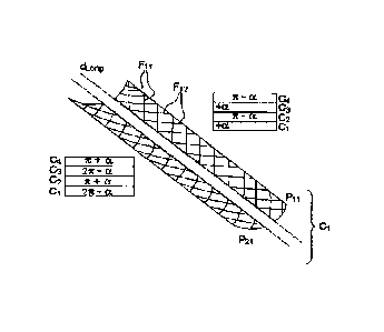
Figure 6 illustrates the principle of a smooth-deployment tape according to
the invention.
The tape 1 extends in a longitudinal direction dumo; it comprises a stack
Emp of fibrous layers Cn, n being the layer number, the layers Cn having
longitudinal symmetry of their fibres.
Advantageously, the layers comprise a composite material comprising an
epoxy or cyanate resin in which carbon, quartz, glass or Kevlar (registered
trade mark) fibres extend. Alternatively, the layers comprise a woven
material.
A layer Cn therefore comprises two parts: a first Pin and a second part
P2n.
The first part P11 of a first layer Cl comprises at least a first type of
fibres
F11, the direction of the fibres F11 forming an angular offset +a with
respect to the longitudinal direction &mtg.
The first part P12 of a second fibrous layer C2 consecutive with the first
layer comprises at least a second type of fibres F12 forming an angular
offset (1T-0) with respect to the longitudinal direction tkong.
The fibres F13 of the first part P13 of the third layer C3 form an angular
offset +a with the longitudinal direction duino. The fibres F14 of the first
part
= P14 of the fourth layer C4 form an angular offset of (Ti-a) with the
longitudinal direction dizna. The stack of the first parts of the layers is
summarized in the table in the top-right of Figure 6. It may therefore be
seen that there is an alternation of values of angular offsets between +a
and (Tr-a).
CA 02916388 2015-12-29
=
9
On the second part P2n of a given layer Cn, the direction of the fibres F2n
forms, with respect to the longitudinal direction dung, an angular offset the
value of which is the opposite of the angular offset that the direction of the
fibres Fin forms in the first part of the layer On. In other words, in the
first
5 part P11 of the first layer Cl the direction of the fibres forms an
angular
offset of +a and on the second part P12 of the first layer Cl the direction Of
the fibres forms an angular offset (2Tr-a), namely (-a) in the anticlockwise
direction. The stack Of the second parts of the layers On is summarized In
the table at the bottom left of Figure 8. It may therefore be seen that there
3. 0 is an alternation of the values of the fibres between the values (2w-a)
and
(rr+a).
Figure 7 depicts a smooth-deployment tape according to the invention and
demonstrates a low torsional deformation generated by variations in
15 temperature as compared with the tape produced according to the prior
art.
In this particular instance, the tape 1 of Figure 7 comprises two layers Cn.
A first layer Cl twists in one direction and a second layer C2 twists in the
other direction when the layers are subjected to variations in temperature.
Combining these two layers Cl and C2 means that the torsional
deformations can be compensated for overall. The resultant forces of the
expansion have substantially equal intensities at all ends of the tape 1 and
the tape experiences no torsion. In this particular instance, the plane of
25 symmetry Psym is maintained and there is no rotation of sections about
the
longitudinal axis of the tape.
Figure 8 depicts a first embodiment of the invention. In this particular
instance, the stack Emp comprises four layers Cl, C2, 09 and C4, each of
30 them exhibiting longitudinal symmetry of the fibres.
The first layer of the stack Cl comprises two parts the direction of the
fibres
of which is symmetric with respect to the longitudinal direction dung.
35 In this case, the first part P11 of the first layer Cl comprises a first
material
Mat1 having a first type of fibres of which the direction forms a first
angular
offset te1 with the longitudinal direction &aro The second part P21,
10
symmetric with respect to the longitudinal direction, comprises the first
material Matl of which
the direction of the first type of fibres forms a second angular offset +a2,
the second angular
offset +a2 corresponding to 2Tr-a, or to -al in the anticlockwise direction.
The second layer of the stack C2 also comprises two symmetric parts
respectively situated
facing the two parts of the first layer Cl.
The first part P12 of the second layer 02 comprises the first material Matl
having the first type
of fibres of which the direction forms a third angular offset +a3 with the
longitudinal direction
dLong, +a3 corresponding to Tr-al. The second part P22 which is symmetric with
respect to the
longitudinal direction dLong comprises the first material Matl of which the
direction of the fibres
forms a fourth angular offset +a4 with respect to the longitudinal direction
dLong, the fourth
angular offset +a4 corresponding to rir +al.
The third layer C3 is identical to the first layer Cl and the fourth layer C4
is identical to the
second layer 02.
According to a first variant of the invention, which has not been depicted in
the figures, the
second part P21 comprises a second material Mat2 with an expansion coefficient
substantially
equal to that of the first material Matl . The second material Mat2 has a
second type of fibres.
The first part Pll of the first layer Cl comprises the material Matl as in the
previous case,
depicted in Figure 8. The second part P22, symmetric with respect to the
longitudinal direction,
comprises the second material Mat2 of which the direction of the second type
of fibres forms the
second angular offset +a2, the second angular offset corresponding to 2ir-al ,
as before.
The second layer C2 of the stack also comprises two symmetric parts situated
respectively
facing the two parts of the first layer Cl.
The first part P12 of the second layer C2 comprises the second material Mat2
having the
second type of fibres the direction of which forms a third angular offset +a3
with the longitudinal
direction in the clockwise direction, +a3 corresponding to "nr-al. The second
part P22 symmetric
with respect to
Date Recue/Date Received 2022-02-25
CA 02916388 2015-12-29
II
the longitudinal direction comprises the first material Matl of which the
direction of the first type of fibres forms a fourth angular offset +a4, the
fourth angular offset +a4 corresponding to rr +al.
5 According to another variant of the invention depicted in Figure 9, the
first
and second parts are split into at least two segments $1 and 82.
In this particular instance, the first part P11 of the first layer Cite split
into
two segments SI and S2 In the longitudinal direction dt.ong.
The first segment Si comprises the first material Matl of which the
orientation of the fibres forms a first angular offset +al with the
longitudinal
direction. The second segment $2 comprises a fibrous third material Mat 4
of which the orientation of the fibres forms a fdth angular offset pi with the
15 longitudinal direction.
The second part P12 of the first layer has longitudinal symmetry. It
comprises two segments SI and 52 comprising the first and third material.
The orientation of each type of fibre in each of the parts is respectively
20 longitudinally symmetric.
The stack on the first part of four layers comprising two segments can be
= summarized as follows (al; (31), (Tr-al; Tr-(3i), (al; pil, (Tr-al; TT-
(31).
25 In another variant depicted in Figure 10a, the tape 1 of which the
direction
of the fibres is symmetric with respect to the longitudinal direction &one
comprises a plurality of zones in a transverse direction thrum perpendicular
to the longitudinal direction dung.
30 In thb instance, the tape comprises two zones Z1 and Z2. The first zone
Z1
of the first layer Cl has longitudinal symmetry between the first P11 and
the second P12 part. For the sake of making Figure 10a easier to
understand, the longitudinal symmetry of the fibres has not been depicted
In this figure.
The first part P11 of the first layer Cl of the first zone Z1 comprises a
fifth
material Mat5 of which the orientation of the fibres forms a sixth angular
CA 02916388 2015-12-29
=
12
offset with the longitudinal direction of value y1. The stack on the first
part
P11 of the first zone 21 comprises the fifth material and the orientation of
the fibres alternates between the values (+y1) and (Tr-y1). The second part
P21 of the first layer Cl of the first zone Z1 is longitudinally symmetric.
The first part P11 of the first layer Cl of the second zone Z2 comprises a
sixth material Mat6 of which the orientation of the fibres forms a seventh
angular offset el with the longitudinal direction &mu. The stack on the first
part P11 of the first zone Z1 comprises the fifth material and the orientation
of the fibres alternates between the values (+c1) and (Tr-c1). The second
part P21 of the first layer Cl of the first zone Z1 is longitudinally
symmetric.
Advantageously, the boundary between the zones comprising different
materials is not linear, as has been depicted in Figure 10b. There is a
section of tape in which the two materials overlap so as not to create a
zone of weakness in the tape 1 or, In other words, zones in which kinking
or tearing could occur.
According to another variant, depicted in Figure 11, the two parts P1 and
P2 of the tape 1 are connected using at least one of the layers Cn of the
stack Emp. In this particular instance, the stack Emp comprises four layers
having symmetry Of the orientation of the longitudinal fibres; the first part
of
one layer Pin and the second part of the next layer P2n+1 are monolithic.
In this instance, the first part of the first layer P11 and the second part of
=
the second layer P22 are monolithic as are the second part of the third
layer P23 and the first part of the fourth layer P14.
The stack Emp could potentally further comprise a substrate on which the
first layer Cl extends. Advantageously, the stack Emp further comprises a
ao non-fibrous layer or a layer in which the fibres are parallel to the
longitudinal direction, which layer is interposed between two fibrous layers
of the stack Emp, Figure 12.
Advantageously, the radius of curvature of the cross section Sec of the
tape in a transverse direction di-env perpendicular to the longitudinal
direction durio varies In the longitudinal direction dong and/or in the
transverse direction them.
CA 02916388 2015-12-29
13
Advantageously, the width of the tape varies in the longitudinal direction so
as to vary the radius of curvature of the winding.
5 According to a second embodiment depicted in Figure 13, the stack Emp
comprises at least two fibrous layers Cl; 02 comprising the first material
Mat1 comprising two types of fibre, each type of fibre being oriented in a
single direction.
in this case, the first part P11 of the first layer Cl comprises a sixth
material Mat 6 comprising a first type of fibre of which the direction forms a
= first angular offset al with the longitudinal direction dung and a second
type
of fibre of which the direction forms a second angular offset 131 with the
longitudinal direction.
The second part of the first layer P21 comprises the sixth material Mat B.
The directions of the first and second types of fibre of the first and second
parts are longitudinally symmetric respectively.
20 The first part P12 of the second layer C2 comprises the sixth material
Mate,
the direction of the first type of fibres forms a fifth angular offset a3
corresponding to Tr-al with the longitudinal direction dLong and the direction
of the second type of fibres forms a sixth angular offset 133, corresponding
to Tr-131 with respect to the longitudinal direction &ono.
The invention solves the technical problem by proposing a solution for
limiting the torsion generated by variations in temperature.
=