Some of the information on this Web page has been provided by external sources. The Government of Canada is not responsible for the accuracy, reliability or currency of the information supplied by external sources. Users wishing to rely upon this information should consult directly with the source of the information. Content provided by external sources is not subject to official languages, privacy and accessibility requirements.
Any discrepancies in the text and image of the Claims and Abstract are due to differing posting times. Text of the Claims and Abstract are posted:
| (12) Patent: | (11) CA 2917201 |
|---|---|
| (54) English Title: | OPTICAL POLARITY MODULES AND SYSTEMS |
| (54) French Title: | MODULES ET SYSTEMES A POLARITE OPTIQUE |
| Status: | Expired and beyond the Period of Reversal |
| (51) International Patent Classification (IPC): |
|
|---|---|
| (72) Inventors : |
|
| (73) Owners : |
|
| (71) Applicants : |
|
| (74) Agent: | GOWLING WLG (CANADA) LLP |
| (74) Associate agent: | |
| (45) Issued: | 2018-02-20 |
| (22) Filed Date: | 2003-09-23 |
| (41) Open to Public Inspection: | 2004-04-08 |
| Examination requested: | 2016-01-11 |
| Availability of licence: | N/A |
| Dedicated to the Public: | N/A |
| (25) Language of filing: | English |
| Patent Cooperation Treaty (PCT): | No |
|---|
| (30) Application Priority Data: | ||||||
|---|---|---|---|---|---|---|
|
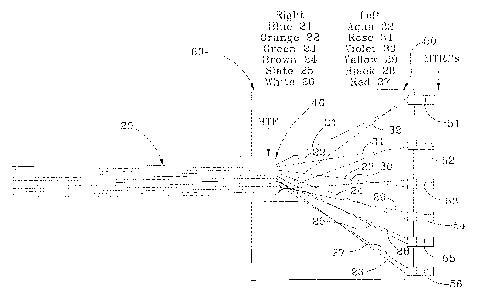
An optical interconnection module (60) having: an enclosure defining walls and a cavity within the walls for receiving and supporting optical fibers (21-32) and connectors (40); an optical interconnection section formed in a wall of the module, the optical interconnection section having a multi- fiber connector (40) with multiple optical paths formed therein, the optical paths being arranged in a generally planar array with the paths being immediately adjacent to at least one other optical path for optical alignment with optical fibers in an optical fiber ribbon (20); an optical connector station (51-56) formed in a wall of the module having a plurality of optical fiber connectors; the optical paths and the optical connectors being optically interconnected by optical fibers disposed in the cavity, fiber pairs being formed by the optical fibers, at least one of the fiber pairs being routed to a respective connector station that is in optical communication with the optical paths.
Un module dinterconnexion optique (60) comprenant une enceinte définissant des parois et une cavité dans les parois pour recevoir et supporter des fibres optiques (21 à 32) et des raccords (40), et une section dinterconnexion optique formée dans une paroi du module, laquelle section dinterconnexion optique comprenant un raccord multifibre (40) dans lequel sont formés de multiples trajets optiques, lesquels trajets optiques sont disposés dans un réseau globalement planaire et sont directement adjacents à au moins un autre trajet optique en vue dun alignement optique avec des fibres optiques dans un ruban de fibres optiques (20). Le module comprend également une station de connecteur optique (51 à 56) formée dans une paroi du module et comprenant une pluralité de raccords de fibres optiques, les trajets optiques et les raccords optiques étant interconnectés optiquement par des fibres optiques disposées dans la cavité, des paires de fibres étant formées par les fibres optiques, au moins une de ces paires de fibres étant acheminée vers une station de connecteur correspondant se trouvant en communication optique avec les trajets optiques.
Note: Claims are shown in the official language in which they were submitted.
Note: Descriptions are shown in the official language in which they were submitted.
2024-08-01:As part of the Next Generation Patents (NGP) transition, the Canadian Patents Database (CPD) now contains a more detailed Event History, which replicates the Event Log of our new back-office solution.
Please note that "Inactive:" events refers to events no longer in use in our new back-office solution.
For a clearer understanding of the status of the application/patent presented on this page, the site Disclaimer , as well as the definitions for Patent , Event History , Maintenance Fee and Payment History should be consulted.
| Description | Date |
|---|---|
| Time Limit for Reversal Expired | 2023-03-23 |
| Letter Sent | 2022-09-23 |
| Letter Sent | 2022-03-23 |
| Letter Sent | 2021-09-23 |
| Common Representative Appointed | 2019-10-30 |
| Common Representative Appointed | 2019-10-30 |
| Grant by Issuance | 2018-02-20 |
| Inactive: Cover page published | 2018-02-19 |
| Letter Sent | 2018-01-15 |
| Change of Address or Method of Correspondence Request Received | 2018-01-10 |
| Inactive: Single transfer | 2018-01-04 |
| Pre-grant | 2018-01-04 |
| Inactive: Final fee received | 2018-01-04 |
| Notice of Allowance is Issued | 2017-08-03 |
| Letter Sent | 2017-08-03 |
| Notice of Allowance is Issued | 2017-08-03 |
| Inactive: Approved for allowance (AFA) | 2017-07-26 |
| Inactive: Q2 passed | 2017-07-26 |
| Amendment Received - Voluntary Amendment | 2017-04-21 |
| Inactive: S.30(2) Rules - Examiner requisition | 2016-10-31 |
| Inactive: Report - No QC | 2016-10-25 |
| Inactive: Cover page published | 2016-02-03 |
| Inactive: IPC assigned | 2016-01-25 |
| Inactive: First IPC assigned | 2016-01-25 |
| Inactive: IPC assigned | 2016-01-25 |
| Divisional Requirements Determined Compliant | 2016-01-14 |
| Letter sent | 2016-01-14 |
| Letter Sent | 2016-01-14 |
| Application Received - Regular National | 2016-01-13 |
| Application Received - Divisional | 2016-01-11 |
| Request for Examination Requirements Determined Compliant | 2016-01-11 |
| All Requirements for Examination Determined Compliant | 2016-01-11 |
| Application Published (Open to Public Inspection) | 2004-04-08 |
There is no abandonment history.
The last payment was received on 2017-09-01
Note : If the full payment has not been received on or before the date indicated, a further fee may be required which may be one of the following
Please refer to the CIPO Patent Fees web page to see all current fee amounts.
Note: Records showing the ownership history in alphabetical order.
| Current Owners on Record |
|---|
| CORNING OPTICAL COMMUNICATIONS LLC |
| Past Owners on Record |
|---|
| LARRY K., JR. SHOOK |
| STEVE C. DEL GROSSO |

