Note: Descriptions are shown in the official language in which they were submitted.
CA 02917303 2016-01-04
4
- 1 -
MECHANICAL STRUCTURAL COMPONENT AND METHOD FOR
MANUFACTURING SAME
TECHNICAL FIELD
5 100011 The disclosure relates to a toothed mechanical structural
component
(case hardening steel member) such as a gear or a spline used in the fields of
building industry machines and automobiles, and a method for manufacturing
the same.
10 BACKGROUND
100021 Members that are subject to repeated stress, such as power
transmission components of automobiles (for example, toothed components
such as gears or splines used in final gears of transmissions, drive shafts,
etc.),
are required to have not only excellent power transmission efficiency but also
15 features such as high fatigue strength and low noise. It is
therefore regarded
as important to improve dimensional accuracy in the part of contact between
members.
100031 Members required to have high dimensional accuracy have
conventionally been formed by machine cutting, but this has the disadvantage
20 of longer processing time and higher manufacturing cost. Hence, cold
forging that achieves excellent dimensional accuracy of the formed product
has been increasingly used in recent years. Moreover, a component formed
by hot forging and a component formed by cold forging differ in
characteristics of the finished component. The cold-forged component, in
25 which fiber flow is formed, tends to have excellent component
characteristics.
For example, Patent Literature (PTL) 1 proposes a method for
manufacturing a tooth profile component by stretch-forming an initial tooth
profile by cold forging and then forming a tooth tip to project from the
initial
tooth profile by cold forging.
30 100041 PTL 2 proposes a manufacturing method whereby a material inserted
in a die is sandwiched between a punch and a knockout with a predetermined
pressing force and, in the sandwiched state, the raw material is formed into a
component by applying an axial pressing force that is larger than the sum of a
knockout pressing force and a forming pressing force to the punch while
Ref. No. P0141370-PCT-ZZ (1/24)
CA 02917303 2016-01-04
- 2 -
rotating the punch, thus enhancing forming accuracy even in the case where
the component has a large twist angle.
CITATION LIST
Patent Literatures
[00051 PTL 1: JP 2006-102821 A
PTL 2: JP 2002-96139 A
SUMMARY
(Technical Problem)
100061 However, with the method of forming the tooth profile and then
forming the tooth tip described in PTL 1, considerable working strain is
introduced in the vicinity of the tooth surface in the tooth profile forming
stage, causing the steel to strain-harden and decrease in plastic
deformability.
As a result, sufficient metal flow is not generated in the following tooth tip
forming stage. Thus, the component may not be able to be accurately formed
to predetermined dimensions.
With the manufacturing method described in PTL 2, finish machining
is needed after cold forging, which inevitably increases the manufacturing
cost.
100071 It could therefore be helpful to provide a toothed mechanical
structural component such as a gear or a spline having excellent dimensional
accuracy and fatigue strength, by combining an optimum cold forging material
and cold forging.
It could also be helpful to provide an advantageous method for
manufacturing the aforementioned toothed mechanical structural component.
(Solution to Problem)
[00081 We made intensive research on cold forging materials and cold forging
methods.
As a result, we discovered that, by combining and controlling a
suitable cold forging material composition and an appropriate cold forging
method, the dimensional accuracy of a toothed component manufactured by
cold forging can be significantly improved as compared with conventional
techniques. We also discovered that noise which has conventionally been a
Ref. No. P0141370-PCT-ZZ (2/24)
CA 02917303 2016-01-04
- 3 -
concern can be significantly reduced by improving the dimensional accuracy
of the teeth, and fatigue strength can be advantageously improved by
suppressing coarsening of austenite grains (that is, prior austenite grains)
after carburizing treatment.
The disclosure is based on the aforementioned discoveries.
100091 We thus provide the following.
I. A mechanical structural component that is a toothed component
obtained by performing cold forging and carburizing treatment on a steel
having a chemical composition that includes, in % by mass:
0.10% to 0.35% C;
0.01% to 0.13% Si;
0.30% to 0.80% Mn;
0.03% or less P;
0.03% or less S;
0.010/u to 0.045% Al;
0.5% to 3.0% Cr;
0.0005% to 0.0040% B;
0.003% to 0.080% Nb; and
0.0080% or less N,
wherein Ti mixed in the chemical composition as an impurity is
limited to 0.005% or less, and the chemical composition has a balance
including Fe and incidental impurities,
in prior austenite grains after the carburizing treatment, an area ratio
of crystal grains of 50 i.,tm or less is 80% or more, and an area ratio of
crystal
grains exceeding 300 tm is 10% or less, and
a total helix deviation of teeth after the carburizing treatment satisfies
Formula (1)
(1313x/L) x 103 5 ... (1)
where Binax is a maximum total helix deviation in all teeth in mm, and L is a
face width in mm.
[0010] 2. The mechanical structural component according to the foregoing 1,
wherein the steel further includes, in % by mass, one or two types
selected from the group consisting of:
0.0003% to 0.50% Sb; and
Ref. No. P0141370-PCT-ZZ (3/24)
CA 02917303 2016-01-04
- 4 -
0.0003% to 0.50% Sn.
[0011] 3. A method for manufacturing a mechanical structural component by
forming, by annealing and cold forging, the steel having the chemical
composition according to the foregoing 1 or 2 into a toothed component and
then performing carburizing treatment on the toothed component,
wherein a reduction in area during tooth forming is in a range of
Formula (2)
19% {(A ¨ TE X (d/2)2)/Al x 100 70% ... (2)
where A is a sectional area before the tooth forming in mm2, and d is a pitch
diameter of the toothed component in mm.
100121 4. The method for manufacturing a mechanical structural component
according to the foregoing 3,
wherein the number of times the annealing is performed before the
tooth forming is 2 or less.
(Advantageous Effect)
[00131 A toothed mechanical structural component having excellent
dimensional accuracy can be obtained by combining an optimum cold forging
material and cold forging method. Such a mechanical structural component
has lower noise and higher fatigue strength.
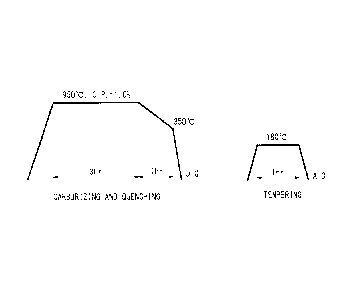
BRIEF DESCRIPTION OF THE DRAWINGS
100141 In the accompanying drawings:
FIG. 1 is a diagram illustrating carburizing heat treatment conditions;
and
FIG. 2 is a diagram illustrating annealing conditions.
DETAILED DESCRIPTION
100151 Detailed description is given below.
The reasons for limiting the chemical composition of the steel to the
aforementioned range are explained first. The %
indications for the
ingredients are "% by mass", unless otherwise stated.
C: 0.10% to 0.35%
0.10% or more C is necessary to achieve, by quenching after
carburizing treatment performed on the cold-forged product, sufficient
Ref. No. P0141370-PCT-ZZ (4/24)
CA 02917303 2016-01-04
- 5 -
hardness in the center portion of the forged product. When the C content
exceeds 0.35%, however, the toughness of the center portion degrades. The
C content is accordingly limited to the range of 0.10% to 0.35%, The C
content is preferably 0.25% or less and more preferably 0.20% or less, in
terms of toughness.
100161 Si: 0.01% to 0.13%
Si is useful as a deoxidizer, and at least 0.01% Si needs to be added.
Si, however, preferentially oxidizes in the carburized surface layer, and not
only accelerates grain boundary oxidation, but also solid-solution-strengthens
ferrite and increases deformation resistance to thereby degrade cold
forgeability. The upper limit of the Si content is therefore 0.13%. The Si
content is preferably in the range of 0.02% to 0.10%, and more preferably in
the range of 0.02% to 0.09%.
100171 Mn: 0.30% to 0.80%
Mn is an element effective in improving quench hardenability, and at
least 0.30% Mn needs to be added. Excess addition of Mn, however, causes
an increase in deformation resistance by solid solution strengthening. The
upper limit of the Mn content is therefore 0.80%. The Mn
content is
preferably 0.60% or less, and more preferably 0.55% or less.
100181 P: 0.03% or less
P segregates to crystal grain boundaries and decreases toughness.
Accordingly, a lower P content is more desirable, though up to 0.03% P is
allowable. The P content is preferably 0.025% or less. Although the lower
limit of the P content is not particularly limited, an unnecessarily lower P
content leads to longer refining time and higher refining cost, and so the P
content may be 0.010% or more. The P content is preferably 0.013% or
more.
100191 S: 0.03% or less
S exists as a sulfide inclusion, and is an element effective in
improving machinability by cutting. Excess addition of S, however, causes a
decrease in cold forgeability. The upper limit of the S content is therefore
0.03%. Although the lower limit of the S content is not particularly limited,
the S content may be 0.010% or more to ensure machinability by cutting.
The S content is preferably 0.012% or more.
Ref. No. P0141370-PCT-ZZ (5/24)
CA 02917303 2016-01-04
-6-
100201 Al: 0.01% to 0.045%
Excess Al fixes N in the steel as AIN, and causes the quenching effect
of B to develop. To
stabilize the component strength after carburizing
treatment, it is important to suppress the development of the quenching effect
of B. The upper limit of the Al content is therefore 0.045%. Since Al is
also an element effective in deoxidation, the lower limit of the Al content is
0.01%. The Al content is preferably in the range of 0.01% to 0.040%, and
more preferably in the range of 0.015% to 0.035%.
100211 Cr: 0.5% to 3.0%
Cr is an element that contributes to not only improved quench
hardenability but also improved resistance to temper softening, and also is
useful in accelerating carbide spheroidizing. When the
Cr content is less
than 0.5%, the effect of the addition is poor. When the Cr content exceeds
3.0%, it facilitates excess carburizing and retained austenite generation, and
adversely affects fatigue strength. The Cr content is accordingly limited to
the range of 0.5% to 3.0%. The Cr content is preferably in the range of 0.7%
to 2.5%, more preferably in the range of 1.0% to 1.8%, and further preferably
in the range of 1.4% to 1.8%.
100221 B: 0.0005% to 0.0040%
B has an effect of reducing solute N by combining with N in the steel.
Thus, B reduces dynamic strain aging during cold forging caused by solute N,
and contributes to lower deformation resistance during forging. To achieve
this effect, 0.0005% or more B needs to be added. On the other hand, when
the B content exceeds 0.0040%, the deformation resistance reduction effect
saturates, and toughness declines. The B content is accordingly limited to
the range of 0.0005% to 0.0040%. The B content is preferably in the range
of 0.0005% to 0.0030%, and more preferably in the range of 0.0005% to
0.0020%.
100231 Nb: 0.003% to 0.080%
Nb has an effect of forming NbC in the steel and suppressing, by a
pinning effect, coarsening of prior austenite grains during carburizing
treatment. "To achieve this effect, at least 0.003% Nb needs to be added.
On the other hand, when the Nb content exceeds 0.080%, the precipitation of
coarse NbC may cause a decrease in coarsening suppressibility and a decrease
Ref. No. P0141370-PCT-ZZ (6/24)
CA 02917303 2016-01-04
- 7 -
i n fatigue strength. The Nb content is accordingly limited to the range of
0.003% to 0.080%. The Nb content is preferably in the range of 0.010% to
0.060%, and more preferably in the range of 0.015% to 0.045%.
[0024] N: 0.0080% or less
N forms a solute in the steel, and undergoes dynamic strain aging
during cold forging and as a result causes an increase in deformation
resistance. N is thus an ingredient the mixing of which in the steel is
preferably avoided as much as possible. The N content is therefore 0.0080%
or less. The N content is preferably 0.0070% or less, and more preferably
0.0065% or less.
100251 Ti: 0.005% or less
Ti is an ingredient the mixing of which in the steel is preferably
avoided as much as possible. In detail, Ti tends to form coarse TiN by
combining with N, and also adding Ti simultaneously with Nb facilitates the
formation of a coarse precipitate and causes a decrease in fatigue strength.
Hence, the mixing of Ti is preferably reduced as much as possible. 0.005%
or less Ti is, however, allowable. The Ti content is preferably 0.003% or
less,
and may be even 0%.
[0026] While the basic ingredients have been described above, the following
elements may also be included as appropriate when necessary according to the
disclosure.
Sb: 0.0003% to 0.50%
Sb is an element effective in suppressing decarburization of the
surface of the steel material and preventing a decrease in surface hardness.
Excess addition of Sb, however, degrades cold forgeability. The Sb content
is therefore in the range of 0.0003% to 0.50%. The Sb content is preferably
in the range of 0.0010% to 0.050%, and more preferably in the range of
0.0015% to 0.035%.
[0027] Sn: 0.0003% to 0.50%
Sn is an element effective in improving the anti-corrosion property of
the surface of the steel material. Excess addition of Sn, however, degrades
cold forgeability. The Sn content is therefore in the range of 0.0003% to
0.50%. The Sn content is preferably in the range of 0.0010% to 0.050%, and
more preferably in the range of 0.0015% to 0.035%.
Ref. No. P0141370-PCT-ZZ (7/24)
CA 02917303 2016-01-04
-8-
100281 The toothed component obtained according to the disclosure is
surface-hardened by carburizing heat treatment. To achieve high fatigue
strength, it is important that the grain size after the carburizing treatment
is
fine.
In detail, in prior austenite grains after the carburizing treatment, the
area ratio of the crystal grains of 50 pm or less needs to be 80% or more, and
the area ratio of the crystal grains exceeding 300 pm needs to be 10% or less.
Preferably, the area ratio of the crystal grains of 50 i..tm or less is 90% or
more,
and the area ratio of the crystal grains exceeding 300 p.m is 5% or less.
100291 While the chemical composition and structure according to the
disclosure have been described above, it is important that the total helix
deviation of the teeth after the carburizing treatment in the disclosed
component satisfies Formula (1):
(Bmax/L) x 103 5 ... (1)
where B3 mx is the maximum total helix deviation in all teeth (mm), and L is
the face width (mm).
[0030] The left side of Formula (I) indicates the degree of accuracy error of
the teeth in one component. When this value exceeds 5, large noise is
inevitable. The value of the left side of Formula (1) is more preferably 3 or
less, and further preferably 2 or less.
Both of such accuracy error that satisfies Formula (1), i.e. high
dimensional accuracy, and sufficient component strength have not been
attainable by conventional steels, and are first attained by the disclosed
steel
cornposition.
[0031] The following describes the disclosed manufacturing method.
The disclosure is intended to enhance the helix accuracy of teeth and
thus reduce noise and improve fatigue strength. The reduction in area during
tooth forming is important for this purpose. In
detail, it is important that the
reduction in area is in the range of Formula (2):
19% {(A¨ lt X (d/2)2)/Al x 100 70% ... (2)
where A is the sectional area before tooth forming (mm2), and d is the pitch
diameter of the toothed component (mm).
100321 In the case where the reduction in area indicated in Formula (2)
exceeds 70%, the critical formability of the steel is exceeded, and cracking
Ref. No. P0141370-PCT-ZZ (8/24)
CA 02917303 2016-01-04
- 9 -
occurs during forging. The
reduction in area during tooth forming is
therefore 70% or less. The
reduction in area during tooth forming is
preferably 60% or less. Meanwhile, to achieve higher fatigue strength by the
formation of fiber flow which is one of the useful effects of cold forging,
the
reduction in area during tooth forming needs to be 19% or more. The
reduction in area during tooth forming is preferably 25% or more.
Note that the cold forging conditions are not particularly limited, and
conventionally known conditions may be used.
100331 After the aforementioned cold forging, carburizing treatment is
performed to obtain the product. In some cases, however, fatigue strength
degraded after the carburizing treatment.
We repeatedly studied this matter, and as a result discovered that, in
the instances where the degradation in fatigue strength was seen, the crystal
grains coarsened after the carburizing treatment.
[00341 We then made research on the cause of this phenomenon, and found
out that the crystal grain coarsening strongly correlates with the number of
times annealing is performed in the cold forging.
In detail, in the case where annealing is performed before or at a
midpoint of the cold forging, while the steel structure before annealing is a
structure of ferrite and pearlite deformed by work, the steel structure after
annealing is a structure in which a spheroidal carbide is dispersed in a
recrystallized ferrite matrix phase.
Recrystallized ferrite is very fine, and
the nucleation site of reverse-transformed austenite during carburizing
heating
increases, so that austenite in the initial stage of carburizing is refined.
Extremely refined austenite is susceptible to abnormal grain growth. We
discovered that this is the reason why the crystal grains tend to coarsen as a
result of annealing. We also
found out that annealing causes the precipitate
to coarsen.
Basically, if the precipitate is fine, the abnormal grain growth of
austenite can be suppressed. In the
case where the precipitate coarsens as a
result of annealing, however, the pinning force of the grain boundaries is
lost,
making it difficult to suppress the abnormal grain growth of austenite. Such
phenomenon becomes more noticeable as annealing is repeated. We
discovered that, when the number of times annealing is performed is 3 or more,
the crystal grains coarsen and the fatigue strength degrades.
Ref No. P0141370-PCT-ZZ (9/24)
CA 02917303 2016-01-04
-10-
100351 Our research has revealed the following. Favorable fatigue strength
is achieved if, in prior austenite grains after the carburizing treatment, the
area ratio of the crystal grains of 50 j..tm or less is 80% or more and the
area
ratio of the crystal grains exceeding 300 um is 10% or less. If
annealing is
performed 3 or more times in the cold forging, however, the crystal grains
coarsen and the aforementioned fine grain structure is unlikely to be
obtained.
Hence, to achieve not only lower noise but also higher fatigue strength,
it is preferable that the number of times annealing is performed before tooth
forming is 2 or less and, in prior austenite grains after the carburizing
treatment, the area ratio of the crystal grains of 50 um or less is 80% or
more
and the area ratio of the crystal grains exceeding 300 um is 10% or less.
Note that the annealing conditions in the cold forging are not
particularly limited, and conventionally known conditions may be used. The
annealing temperature is preferably about 760 C to 780 C.
Moreover, the carburizing treatment conditions are not particularly
limited, and conventionally known conditions may be used. In
typical
treatment, the steel material is carburized at 900 C to 960 C in a
carburizing
gas atmosphere and then quenched, and further tempered at 120 C to 250 C.
[0036] Crystal grain coarsening during carburizing can also be suppressed by
fine particle distribution of Al nitride or Nb carbonitride. However, when
annealing is performed a plurality of times, Al nitride or Nb carbonitride
coarsens, and as a result loses the crystal grain coarsening suppressibility
during carburizing. It is
therefore preferable to limit the number of times
annealing is performed to 2 or less. The number of times annealing is
performed is more preferably 1 or less.
EXAMPLES
100371 The structures and function effects according to the disclosure are
described in more detail below, by way of examples. Note that the disclosed
component and method are not limited to the following examples, and
modifications can be made as appropriate within the range in which the
subject matter of the disclosure is applicable, with such modifications being
also included in the technical scope of the disclosure.
100381 (Example 1)
Ref. No. P0141370-PCT-ZZ (10/24)
CA 02917303 2016-01-04
- 11 -
Steels having the respective chemical compositions shown in Table 1
were each obtained by steelmaking, and formed into a round bar with a
diameter of 39.5 mm to 90 mm by hot rolling. The obtained round bar as a
material was cold-forged into the involute gear shape shown in Table 2, and
then was subject to carburizing heat treatment under the conditions
illustrated
in FIG. I. In Table 1, each steel whose Ti content is 0.001% or 0.002% is
steel in which Ti is not added actively but mixed as an impurity.
Respective gears after the carburizing heat treatment were prepared
for the prior austenite grain size measurement and for the helix accuracy
measurement and fatigue test. The prior austenite grain size and the helix
accuracy were measured, and further the fatigue test was conducted.
The results are shown in Table 3.
100391 The prior austenite grain size and the area ratio of crystal grains
after
the carburizing heat treatment were measured as follows. Ten fields of each
of the 0.3 mm inside, 0.5 mm inside, 0.7 mm inside, and 1.0 mm inside
positions immediately below the pitch circle of the teeth were photographed
by an optical microscope with 400 magnification and, for 40 fields in total,
the area ratio of the crystal grains of 50 i_tm or less and the area ratio of
the
crystal grains exceeding 300 1.1.m were quantified using image analysis
software (Image-Pro#PLUS manufactured by Media Cybernetics, Inc.).
The helix accuracy was measured as follows. The total helix
deviation was measured from both sides of all teeth by a three-dimensional
shape measurement instrument in compliance with JIS B 1702-1, and the left
side of Formula (1) was calculated from the maximum total helix deviation
Bina, and the face width L.
The gear fatigue test was conducted as follows. The gear was tested
at 1800 rpm using a power circulation type gear fatigue tester to determine
the
fatigue limit strength (load torque) for 107 times, and the noise in this
strength
was measured by a noise meter. This test is based on the assumption that
fatigue strength of 200 N=m or more is sufficient and noise of 80 dB or less
is
favorable.
Ref. No. P0141370-PCT-ZZ (11/24)
Table 1
0
1
Steel Chemical composition (mass%)
1 .r....
Remarks
_
symbol C Si Mn P S Al N Cr B Nb Ti Sn
Sb
A 0.11 0.05 0.53 0.013 0.012 0.03 0.0051
1.56 , 0.0022 0.031 0.001 Conforming steel
cr
B 0.16 0.05 0.58 0.013 0.012 0.03 0.0062
1.4 0.0019 0.028 0.001 - Conforming steel ,-
-,-
C 0.18 0.05 0.44 0.013 0.012 0.02 0.0061 1.7
0.0011 0.032 0.001 - - Conforming steel 2--
D 0.19 0.04 0.41 0.013 0.012 0.03 0.0064
1.2 0.0006 0.029 0.001 - - Conforming steel
E 0.21 0.09 0.36 0.013 0.012 0.04 0.0048
2.5 0.0015 0.049 0.001 - 0.01 Conforming steel
F 0.22 0.03 0.74 0.013 0.012 0.02 0.0029 0.5
0.0018 0.011 0.001 0.01 - Conforming steel
G 0.28 0.13 0.51 0.013 0.012 0.01 ,
0.0068 1.2 0.0019 0.033 0.001 - - , Conforming
steel P
H 0.34 0.11 0.43 0.013 0.012 0.03 0.0079
2.8 0.0016 0.079 0.001 - - Conforming steel
1-
1 0.25 0.15 0.62 0.012 0.012 0.03 0.0051 1.3
0.0020 0.03 0.002 - - , Comparative steel
...3
,...
0
,...
J 0.27 0.03 0.82 0.013 0.012 0.03 0.0045 1.2
0.0012 0.026 0.001 - - Comparative steel
.
0
1-
K 0.20 0.05 0.49 0.012 0.013 0.05 0.0044
1.2 0.0016 0.043 0.001 - - Comparative steel
1
0
1-
L 0.22 0.01 0.55 0.013 0.012 0.03 0.0082
1.5 0.0026 0.021 0.001 - - Comparative steel
0.
M 0.28 0.11 0.71 0.012 0.012 0.03 0.0035 0.4
0.0016 0.026 0.001 - - Comparative steel
N 0.21 0.06 0.52 0.012 0.013 0.02 0.0054
3.1 0.0009 0.018 0.002 - - Comparative steel
x 0 0.13 0.05 0.66 0.012 0.012 0.03 0.0055 1.5
0.0004 0.025 0.001 - - Comparative steel
a
:-, P 0.29 0.05 0.42 0.012 0.012 0.03 0.0029 1.6
0.0016 0.033 0.013 - - Comparative steel
Z
o Q 0.21 0.20 0.89 0.012 0.013 0.03 0.0125 1.1
0.0001 0.001 0.001 - - Comparative steel
"C.c..i) R 0.18 0.05 0.41. 0.012 0.013 0.03 0.0036
1.1 0.0021 0.001 0.025 - - Comparative steel
-.4
_
L..,
---.
.1cJ
C-)
H
N
F.)
r.)
A
=
CA 02917303 2016-01-04
- 13 -
[0041] [Table 2]
Table 2
Involute gear specifications
Large diameter (mm) 38
Small diameter (mm) 33.5
Module 1
Pressure angle ( ) 35
Number of teeth 36
Reference pitch diameter (mm) 36
Base diameter (mm) 29.4895
Face width (mm) 30
Ref. No. P0141370-PCT-ZZ (13/24)
..
,
,
Table 3
-
o
0
Prior a ustenite grain
A
Annealini,..., Diameter before
Fatigue
1-4
Steel Middle side of Area
ratio of crystal Arear ratio of crystal Left side of Noise -
No. count gear forging
stren'iith
Remarks
symbol Formula (2) grains of 50 um or
grains exceeding 300 Formula ( I) (dB)
(times) (mm)
(Nim) H
less (%) um (%)
cr
.
-
I A 0 , 50 48.1 93 2 1.8
238 70 Example_____ CD
2 B 0 50 48.2 94 1 1.6
254 68 Example
t.....)
3 C 0 50 48.2 93 /
- 1.9
245 72 Example
4 D 0 55 57.2 91 3 2.3
225 72 Example
E 0 65 69.3 95 /
_ 4.8
205 78 Example
6 F 0 55 57.2 87 10 1.9
235 68 Example
P
7 G 0 60 64.0 91 5 2.9
215 78 Example o
1.,
,..
8 14 0 45 36.0 95 4 2.5
224 72 Example
....1
L.
9 A 0 80 79.7 91 6 5.1
186 83 Comparative Example o
L.
NO
B 0 39.5 16.9 81 15 3.5 i 74 77
Comparative Example 0
i-i
-
..,
'
II C 0 90 84.0 88 9 5.3
184 85 Comparative Example A o
i-i
'
12 1 0 55 57.2 85 10 5.6
190 84 Comparative Example 0
.i.
13 J 0 45 36.0 87 8 5.1
176 87 Comparative Example
14 K 0 40 19.0 91 6 5.3
188 84 Comparative Example
L 0 55 57.2 89 8 5.2 i 84 81
Comparative Example
a
16 M 0 60 64.0 90 6 1.9
166 78 Comparative Example
7.
P 17 N 0 65 69.3 92 4 5.3
97 83 Comparative Example
ho 18 0 0 45 36.0 88 7 1.8
192 74 Comparative Example
0
_______________________________________________________________________________
____________________
-
A 19 P 0 60 64.0 71 19 5.6
179 81 Comparative Example
-
lo..)
10 Q 0 55 57.2 77 15 5.1
178 84 Comparative Example
--4
F
-0 21 R 0 55 57.2 68 21 5.9
182 88 Comparative Example
l')
H
14,7
N
,--.
4,
t..)
4,
=
CA 02917303 2016-01-04
- 15 -
[0043] As shown in Table 3, in the case where the left side of Formula (1)
indicating the helix accuracy was 5 or less, the noise was reduced to 80 dB or
less. Moreover, in the case where the steels having the
chemical
compositions satisfying the disclosed range were used and the value in
Formula (2) was in the range of 19% to 70%, the prior austenite grain size
satisfied the aforementioned conditions and high fatigue strength of 200 N=m
or more was achieved.
100441 (Example 2)
Steels A, B, C, Q, and R used in Example 1 were each formed into a
round bar of 50 mm in diameter by hot rolling. The obtained round bar was
annealed under the conditions illustrated in FIG. 2, cold-forged into the
involute gear shape shown in Table 2, and then was subject to carburizing heat
treatment under the conditions illustrated in FIG. 1.
After the carburizing heat treatment, the prior austenite grain size and
the helix accuracy were measured, and then the fatigue test was conducted.
The results are shown in Table 4.
The reduction in area during the cold forging and the prior austenite
grain size measurement, helix accuracy measurement, and fatigue test after
the carburizing heat treatment were the same as the methods in Example I.
Ref. No. P0141370-PCT-ZZ (15/24)
Table 4
Prior austenite grain
Annealing Diameter before
Fatigue (./1
Steel count gear forging, Middle side of Area
ratio of crystal Arear ratio of crystal Left side of strength NO o is
e
No.
Remarks
symbol (times) Formula (2) grains of 50 um or
grains exceeding 300 Formula(Nin) (1) (dB)
(inni)
¨3
less (%) um (u,,o)
P.)
cr
23 A 1 50 48.2 92 3 1.7
225 74 Example
ro
24 B I 50 48.2 93 3 1.5
249 70 Example
25 C 1 50 48.2 91 2 1.8
251 69 Example
26 Q 1 50 48.2 75 21 5.1
186
81
Comparative Example
27 R 1 50 48.2 67 18 5.5
187 84 Comparative Example
0
0
01
\
0
0
0
0
=
CA 02917303 2016-01-04
- 17 -
[00461 As shown in Table 4, with steels A, B, and C having the chemical
compositions satisfying the disclosed range, high fatigue strength of 200 N=m
or more was achieved by setting the number of annealing operations to 1 and
controlling the value in Formula (2) to be in the range of 19% to 70%. On
the other hand, with steels Q and R having the chemical compositions not
satisfying the disclosed range, desired fine grains were not obtained and so
favorable fatigue strength was not achieved even by setting the number of
annealing operations to l and controlling the value in Formula (2) to be in
the
range of 19% to 70%.
[00471 (Example 3)
Steels A, B, C, Q, and R used in Example 1 were each formed into a
round bar of 45 mm in diameter by hot rolling. The obtained round bar was
annealed under the conditions illustrated in FIG. 2, and cold-forged into a
round bar of 50 mm in diameter. Subsequently, the round bar was annealed
again under the conditions illustrated in FIG. 2, cold-forged into the
involute
gear shape shown in Table 2, and then was subject to carburizing heat
treatment under the conditions illustrated in FIG. 1.
After the carburizing heat treatment, the prior austenite grain size and
the helix accuracy were measured, and then the fatigue test was conducted.
The results are shown in Table 5.
The reduction in area during the cold forging and the prior austenite
grain size measurement, helix accuracy measurement, and fatigue test after
the carburizing heat treatment were the same as the methods in Example I.
Ref No. P0141370-PCT-ZZ (17/24)
Table 5
Prior austenite gain
Annealing Diameter before
Fatigue
count gear forging
Steel Middle side of Area
ratio of crystal Arear ratio of crystal Left side of Noise
No.
strength Remarks
symbol grans o um or grans exceeding (times) (
Formula (2) i f 50 i di 300 Formula ( I) mm) (N)-m) (dB)
less (%) um (%)
Cr
28 A 2 50 48.2 90 4 1.7
221 70 Example
29
50 48.2 92 4 1.7
254 73 Example
30 C 2 50 48.2 90 4 1.6
235 75 Example
31
50 48.2 76 19
5.1 186
Comparative Example
32
50 48.2 71 20 5.5
187 86 Comparative Example
0
0
0
00
0
0
co
44.
r"`.i
00
-t:3
4,
CA 02917303 2016-01-04
=
- 19 -
[0049] As in Example 2, as shown in Table 5, with steels A, B, and C
according to the disclosed examples, high fatigue strength of 200 N=m or more
was achieved by setting the number of annealing operations to 2 and
controlling the value in Formula (2) to be in the range of 19% to 70%. On
5 the other hand, with steels Q and R according to the comparative
examples,
desired fine grains were not obtained and so favorable fatigue strength was
not achieved even by setting the number of annealing operations to 2 and
controlling the value in Formula (2) to be in the range of 19% to 70%.
100501 (Example 4)
10 Steels A, B, C, Q, and R used in Example 1 were each formed into a
round bar of 40 mm in diameter by hot rolling. The obtained round bar was
annealed under the conditions illustrated in FIG. 2, and cold-forged into a
round bar of 45 mm in diameter. Subsequently, the round bar was annealed
again under the conditions illustrated in FIG. 2, and cold-forged into a round
15 bar of 50 mm in diameter. Subsequently, the round bar was annealed again
under the conditions illustrated in FIG. 2, cold-forged into the involute gear
shape shown in Table 2, and then was subject to carburizing heat treatment
under the conditions illustrated in FIG. 1.
After the carburizing heat treatment, the prior austenite grain size and
20 the helix accuracy were measured, and then the fatigue test was
conducted.
The results are shown in Table 6.
The reduction in area during the cold forging and the prior austenite
grain size measurement, helix accuracy measurement, and fatigue test after
the carburizing heat treatment were the same as the methods in Example I.
Ref. No. P0141370-PCT-ZZ (19/24)
=
Table 6
Prior a ustenite grain
-
Annealing Diameter beforeFat hme
Steel Middle side of Area
ratio of crystal Arear ratio of crystal Left side of Noise
No.o count gear forging
strength Remarks
symbol Formula (2) 141:air-Is of 50 larn
or grains exceeding 300 Formula (1) (dB)
(times) (mm)
(N .m)
less (%) lant (
33 A 3 50 48.2 80 13 3.6
183 76 Comparative Example el'
34 B 3 50 48.2 81 12 2.8
174
79
Comparative Example
35 C 3 50 48.2 78
10 1.9 194
71
Comparative Example
36 Q 3 50 48.2 74 23 5.9
178 83 Comparative Example
37 R 3 50 48.7 69 25 6.1
182 89 Comparative Example
0
0
t1.-)
01
0
0
0
0
"!0
N.)
I.
CA 02917303 2016-01-04
. =
=
-21-
100521 As shown in Table 6, in the case where annealing was performed 3
times before tooth forming, favorable fatigue characteristics were not
obtained regardless of the chemical composition.
Ref. No. P0141370-PCT-ZZ (21/24)