Note: Descriptions are shown in the official language in which they were submitted.
CA 02917556 2016-01-06
WO 2015/008203
PCT/IB2014/063035
1
DESCRIPTION
"Connection system of piping"
[0001] The present invention relates to a connection system
of piping, wherein said piping is a part of distribution
systems of pressurised or depressurised fluids.
[0002]Specifically, the connection system of the present
invention is suitable to connect a piping to a further
piping, e.g. of the same diameter or different diameters,
or to a valve, or components or machines that require
pressurised or depressurised fluid to operate.
[0003]Moreover, such piping comprises at least a section
of rigid bar or it totally consists of a rigid bar, and
on its outer surface it comprises a plurality of grooves
which extend along said bars.
[0004]Such connection systems have the need not to be
subjected to the action of the pressurised or
depressurised fluid which flows therein, for example by
preventing them from being modified in shape and from
extracting from the piping, and preventing any type of
leaks. Therefore, said connection systems, in addition to
sealingly engaging the respective piping, must be
particularly resistant and finally retain their position
in the piping in an integral manner.
[0005] Connection systems adapted to solve this type of
problems are known in the prior art. Specifically,
81793758
2
reference is made for example to document EP0919758 in the name
of the Applicant.
[0006] However, the known connection systems have a number of
drawbacks.
[0007] Often, such systems are particularly complex, comprising
generally a joint element that has at least a portion of the
same shape as the piping and also having appropriate means
which apply clamping forces on the piping and on said portion
of the joint to obtain the mutual blocking. In fact, the design
and production of the joint, aimed to recreate at least in a
portion the shape of the piping, as well as its blocking to
said piping, are particularly complex and laborious.
[0008] The object of the present invention therefore is to meet
the above needs by providing a connection system having a
simpler structure and implementation.
[0009] In an embodiment of the present disclosure, there is
provided a connection system of piping for distribution systems
of pressurised or depressurised fluids, wherein said piping
comprises at least a section of rigid bar, is quadrangular in
shape, which extends longitudinally and, internally, has a hole
for the passage of the fluid, and, on an outer surface of the
bar, at corners of the bar, four, dovetailed, grooves are made
radially and delimited laterally by two rims, wherein the
connection system comprises: a connection joint comprising an
insertion portion insertable in the hole and a retention
portion, circular, projecting from the piping when the joint is
inserted therein, which outwardly at least one retention slot;
retention means suitable to longitudinally retain the
Date Recue/Date Received 2020-09-21
81793758
2a
connection joint to the piping, said retention means
comprising: i) a retention element suitable to engage the
retention portion inserting itself therein said retention slot;
and ii) clamping means suitable to act with the rims of two
consecutive grooves and with the retention element, and
suitable to exert a clamping force to block the retention
element to the piping comprising an upper clamp and a lower
clamp respectively having a first tooth and a second tooth
suitable for being placed inside the respective groove engaging
the respective rim and wherein the upper clamp and/or the lower
clamp has a channelling; wherein the retention element
comprises: at least one bracket having a retention blade,
arched, suitable to engage the retention slot, and two clamping
branches, which extend perpendicularly to the sides of the
retention blade suitable to engage with the clamping means,
housing the clamping branch, to block the retention element and
thus the joint to the piping wherein the clamping branches
comprise at least one blocking portion, which extends from the
respective clamping branch, and engaging with the clamping
means prevents the longitudinal translation of the bracket.
[0010] The object of the present invention is described in
detail hereafter, with the aid of the accompanying drawings, in
which:
[0011] - figure 1 is a perspective view of a connection system
of piping, mounted on a section of rigid bar part
Date Recue/Date Received 2020-09-21
CA 02917556 2016-01-06
WO 2015/008203
PCT/IB2014/063035
3
of said piping, according to a preferred embodiment;
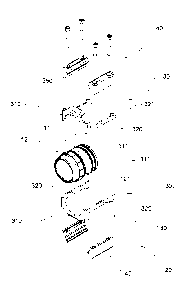
[0012]- figure 2 is an exploded view of the connection
system of piping in figure 1;
[0013]- figure 3 is a perspective view of the connection
system in figures 1 and 2;
[0014]- figure 4 is a longitudinal sectional view of the
connection system in figure 1;
K0151- figure 5 is a back view of the connection system
in figure 3;
[0016]- figure 6 is a perspective view of a part of a
connection system of piping, mounted on a section of
rigid bar part of said piping, according to a further
embodiment.
K0171 With reference to the above drawings, reference
numeral
[0018]1 indicates as a whole a connection system of piping
500 for distribution systems of pressurised or
depressurised fluids.
[00191 Preferably, said piping 500 comprises at least a
section of a rigid bar 501 which extends longitudinally
and which, internally, has a hole 510 for the passage of
the fluid. In further preferred embodiments, piping 500
in its entirety is formed by a rigid bar 501 which
extends in a preferred direction of implementation, for
example in a straight line, but also in a curvilinear
CA 02917556 2016-01-06
WO 2015/008203
PCT/IB2014/063035
4
manner.
[0020] Preferably, hole 510 for the passage of the fluid is
circular; hole 510 is preferably centrally located to
piping 500.
[0021] Preferably, the rigid bar 501 on its outer surface
505 includes a plurality of grooves 520, dovetailed,
outwardly open. Preferably, said grooves extend along the
whole extension of piping 500.
[0022]According to a preferred embodiment, wherein the
rigid bar 501 has a quadrangular shape and, on the outer
surface 505, at its corners, four grooves 520 are
radially formed, bounded laterally by two edges 521.
[0023] Preferably, externally, said piping 500 is square
and therefore has four equal sides.
[0024]In other embodiment variants, said piping 500 is
rectangular and has essentially two square piping one
above the other. Preferably, on the centre line of the
two long sides, externally, said piping 500 in turn has
grooves 520.
[0025]According to a preferred embodiment, the connection
system 1 comprises a connection joint 10 comprising an
insertion portion 11 insertable in hole 510 so as to seal
it and a retention portion 12, projecting from piping 500
when joint 10 is inserted therein, adapted, as described
further below, to engage appropriate components for the
CA 02917556 2016-01-06
WO 2015/008203
PCT/IB2014/063035
retention of joint 10 to, and in, piping 501.
[0026]According to a preferred embodiment, the insertion
portion 11 comprises, for performing said sealed
connection, one or more 0-rings 111 located externally on
5 the insertion portion 11 adapted to engage the inner
surface of hole 510.
[0027]Preferably, the connection joint 10 is adapted to
create a connection with piping 500 for the passage of
compressed air with valves, further piping for example
having the same diameter or different diameters and
shapes; specifically, joint 10 comprises a hooking
portion 15, after the retention portion 12, in turn
positioned outside piping 500, adapted for the aforesaid
purposes and to perform the above interactions. In some
embodiments, the hooking portion 15 has a threaded
surface 151, for example internally or externally.
[0028]In further embodiments, for example for the
connection of two identical piping 500, joint 10 does not
, have the hooking portion 15 but a further retention
portion 12 and a further insertion portion 11 specific
for the engagement with the second piping 500.
[0029]According to a preferred embodiment, the retention
portion 12 outwardly has at least one retention slot 121.
[0030] Preferably, said retention slot 121 extends
continuously peripherally to the connection joint 10,
CA 02917556 2016-01-06
WO 2015/008203
PCT/IB2014/063035
6
[0031] Preferably, said retention slot 121 extends
circularly about the connection joint 10.
[0032] Preferably, the connection system 1 further includes
retention means 20 adapted to longitudinally retain the
connection joint 10 to piping 500, in such a way that the
force of the pressurised or depressurised fluid does not
longitudinally move joint 10.
[003]According to a preferred embodiment, the retention
means 20 comprise:
K0341i) a retention element '30 suitable to engage the
retention portion 12 constraining the joint 10
longitudinally; and
[0035] ii) clamping means, 40 suitable to act in conjunction
with a least one groove 520 and with the retention
element 30, and suitable to. exert a clamping force to
block the retention element 30 to piping 500.
[0036]In other words, the retention element 30 is suitable
to engage, inserting therein, said retention slot 121
present on the retention portion 12 and by the clamping
means 40 said retention element 30 is kept fixed to
piping 500 so to block joint 10.
[0037] According to a preferred embodiment, the clamping
means 40 apply said clamping force on rims 521 of two
consecutive grooves 520, in which the clamping means 40
comprise an upper clamp 41 and a lower clamp 42
CA 02917556 2016-01-06
WO 2015/008203
PCT/IB2014/063035
7
respectively having a first tooth 411 and a second tooth
412 adapted to be placed inside the respective groove 520
engaging the respective rim 521.
[0038] Substantially, the clamping means 40 are therefore
adapted to be clamped on piping 500 by operating on two
consecutive grooves 520.
[0039]According to a preferred embodiment, the clamping
means 40 comprise two pairs of clamps 400, each
comprising an upper clamp 41 and a lower clamp 42
positioned at opposite sides of piping 500.
[0040] Preferably, the clamping means 40 comprise at least
one clamping screw 45 suitable, following its rotation,
.to clamp the upper clamp 41 and the lower clamp 42 on the
respective grooves 520 reciprocally drawing them together
along the direction of extension of said screw 45.
Preferably, the number of clamping screws 45 varies
according to =the length of the clamps. In other words,
there are embodiments that provide a plurality of
clamping screws 45 arranged spaced apart along the
direction of extension of the respective pair of clamps
400, and thus of piping 500.
[0041] According to a preferred embodiment, the retention
element 30 comprises at least one bracket 300 having a
retention blade 310 suitable to engage the retention
portion 12; preferably in the retention slot 121, and two
CA 02917556 2016-01-06
WO 2015/008203
PCT/IB2014/063035
8
clamping branches 320, which extend laterally to the
sides of the retention blade 310, perpendicular thereto,
suitable to engage with the clamping means 40 to block
the retention element 30 and thus joint 10 to piping 500.
[0042] In other words, bracket 300 basically has a "U" or
"C" shape, having the two branches 320 which extend along
piping 500 on the opposite sides thereof, and the
retention blade 310 that joins them.
[0043] Preferably, the retention blade 310 is shaped in
accordance with the shape of the retention groove 121 in
such a manner that blade 310 is housed in the latter with
a geometrical coupling. Preferably in fact, blade 310 is
adapted to house in the retention groove 121 so as to
interact with the rims thereof, thus obtaining the
longitudinal retention of the connection joint 10.
[0044] In a preferred embodiment, the retention slot 121 is
circular and the retention blade 310 is arched.
[0045] According to a preferred embodiment, said upper
clamp 41 and/or said lower clamp 42 have a channelling
410, 420 adapted to house the clamping branch 320.
Preferably, therefore, the walls of channelling 410 and
420 are adapted, when the clamping means 40 are clamped
on piping 500, to engage the clamping branch 320 or the
respective clamping branch 320 and relieve the clamping
forces thereon.
CA 02917556 2016-01-06
WO 2015/008203
PCT/IB2014/063035
9
[0046]According to a preferred embodiment, moreover,
[0047]the clamping branches 320 comprise at least one
blocking portion 321, which extends from the respective
clamping branch 320, and engaging with the clamping means
40 prevents the longitudinal translation of bracket 300.
[0048]In some embodiments, the clamping branch 320
includes a blocking portion 321, for example in the shape
of a tooth, or a bulge, or a camber, or a tab, or a
generic projection which engages the clamping means 40 so
as to create a further obstacle to the longitudinal
translation of bracket 300.
[0049]Preferably, the blocking portion 321 is placed at
the end of the blocking branch 320 and protrudes, for
example, longitudinally, from the respective clamp 41, 42
(as shown in the embodiments in figures 1 to 5) or in
general it protrudes from the clamping means 40.
[0050]According to further embodiments, instead, the
blocking portion 321 is made at a predefined distance
from the retention blade 300 and acts in conjunction with
the respective clamp 41, 42 inside channelling 410, 420
which has a blocking cavity suitable to house said
blocking portion 321. Preferably, said blocking cavity is
formed on channelling 410, 420. In other words, in said
embodiment the clamping branch 320, and in particular the
clamping portion 321 does not protrude from the clamping
CA 02917556 2016-01-06
WO 2015/008203
PCT/IB2014/063035
means 40, but remains therein, once clamped.
[0051] In a further embodiment, the blocking portion 321 is
formed at a predetermined distance from the retention
blade 300, by means of a special shaping of the clamping
5 branch 320 and cooperates with the respective clamp 41,
42 inside channelling 410, 420 which has a blocking
housing 415 suitable for housing said blocking portion
321 (specifically, note the embodiment in figure 6). In
particular in said embodiment, the clamping branch 320
10 has a specific shape while the blocking housing 415 is
suitable for housing said shaped portion of branch 320
having complementary geometry.
[0052]In a preferred embodiment, furthermore, bracket 300,
and in particular the retention blade 320 includes a
strengthening portion 350 suitable for strengthening
bracket 300 in such a manner that, when subjected to
longitudinal forces, it is not bent or does not rotate.
[0053j In other words, said strengthening portion 350
extends perpendicularly by a certain distance from the
retention blade 310, for example along the side surface
505 of piping 500. In some embodiments, therefore, as a
result of the action of forces applied to bracket 300,
the retention blade 310 remains in position thanks to the
presence of the strengthening portion 350 which
optionally rests on the outer surface 505 of piping 500..
CA 02917556 2016-01-06
WO 2015/008203
PCT/IB2014/063035
11
[0054]According to a preferred embodiment, the retention
eiement 30 comprises two brackets 300 positioned opposite
each other and clamped on joint 10 by means of the
clamping means 40. The two brackets 300, therefore,
clamped by the clamping means 40, are adapted to clamp
about the connection joint 10, for example by engaging it
at 360 .
[0055] Embodiments of the connection system 1 are also
provided wherein the retention element 30 is formed in
one piece with the retention means 40.
[0056]In other words, the special retention elements 40
are made in a single piece with the upper clamp 41 and/or
with the lower clamp 42, and are suitable to engage the
connection joint 10, specifically engaging the retention
portion 12, for example inserting into the respective
retention slot 121.
[0057]In further embodiments, for example, the retention
element 30 is made in one piece with the upper clamp 41
and/or with the lower clamp 42, respectively joining two
opposite upper clamps 41 and/or two opposite lower clamps
42.
[0058] For example, two upper clamps 41, and similarly two
lower clamps 42 are, in one piece, joined to each other
by the retention element 30. In other words, two clamps
at the opposite sides of a piping 500 are joined, for
CA 02917556 2016-01-06
WO 2015/008203
PCT/IB2014/063035
12
example by a portion similar to the retention blade 300.
K0591 Innovatively, the connection system object of the
present invention is adapted to solve the prior art
problems continuing to meet the needs of the application
field.
[0060] Advantageously, in fact, the connection system
object of the present invention has a simpler structure
than those typical of the prior art.
[00611 Moreover, advantageously, the connection system
W comprises a connection joint having a simpler geometry
than those typical of the prior art which, in fact, does
not need to have at least a portion thereof which has the
same shape as the piping with which it cooperates.
Advantageously, the connection system of the present
invention gains in simplicity of design and manufacture
of the various components, with particular focus on the
connection joint.
[0062] According to a further advantageous aspect, the
longitudinal movement of the connection joint is obtained
by a suitable retention element which cooperates with
said joint, and only said retention element is fixed in a
direct manner to the piping, distributing the relative
forces involved on specific components.
[0063] According to a still further advantageous aspect,
the retention means retain the same shape regardless of
CA 02917556 2016-01-06
WO 2015/008203
PCT/IB2014/063035
13
the embodiment of the connection joint which, for
example, varies according to the type of connection to be
performed, between two piping of different diameters or
with a valve.
[0064] Advantageously, the components that need to perform
the seal inside the piping, those that carry out the
longitudinal retention and those that perform the
clamping are separate from one another, and therefore,
from a design viewpoint, each of said three components is
W designable and improved separately from the other
according to specific needs.
[0065] A man skilled in the art may make several changes or
replacements of elements with other functionally
equivalent ones to the embodiments of the connection
system object of the present invention in order to meet
specific needs. Also such variants are included within
the scope of protection as defined by the following
claims.
[0066]1'loreover, each variant described as belonging to a
possible embodiment is implementable independently of the
other variants described.