Note: Descriptions are shown in the official language in which they were submitted.
i
CA 02917846 2016-01-08
WO 2015/030732 PCT/US2013/056839
ENCAPSULATED EXPLOSIVES FOR DRILLING WELLBORES
BACKGROUND
[0001] The exemplary
embodiments described herein relate to
systems and methods for drilling operations that use encapsulated explosives
to
complement the performance of downhole cutting tools.
[0002] Downhole cutting tools
are commonly used to drill wellbores
into subterranean formations in the oil and gas industry. Typical drilling
action
associated with downhole cutting tools includes cutting elements that
penetrate
or crush adjacent formation materials and remove the formation materials using
a scraping action. Drilling fluid circulated during drilling may also be
provided to
perform several functions including washing away formation materials and other
downhole debris from the bottom of a wellbore, cleaning associated cutting
structures and carrying formation cuttings radially outward and then upward to
an associated well surface.
[0003] The rate of penetration
of the downhole cutting tool is one
measure of drilling efficiency. As the rate of penetration is increased, the
abrasive wear of the downhole cutting tool increases. Wearing of the downhole
cutting tool necessitates periodic replacement of the downhole cutting tool.
Replacement involves ceasing drilling operations, tripping the worn downhole
cutting tool to the surface and subsequently tripping a new or refurbished
downhole cutting tool into place within the wellbore. Accordingly, replacing a
downhole cutting tool can be quite a costly and time-consuming process.
BRIEF DESCRIPTION OF THE DRAWINGS
[0004] The following figures
are included to illustrate certain aspects
of the exemplary embodiments described herein, and should not be viewed as
exclusive embodiments. The subject matter disclosed is capable of considerable
modifications, alterations, combinations, and equivalents in form and
function,
as will occur to those skilled in the art and having the benefit of this
disclosure.
[0005] FIG. 1 illustrates a
system suitable for drilling a wellbore
penetrating a subterranean formation
[0006] FIGS. 2A and 2B
illustrate a drill bit in a top view and a
cross-sectional view, respectively, that includes a sonicator for triggering
the
1
CA 02917846 2016-01-08
WO 2015/030732 PCT/US2013/056839
encapsulated explosives described herein according to at least one embodiment
described herein.
[0007] FIG. 3 illustrates a
reamer that includes hardware for
triggering the encapsulated explosives described herein according to at least
one
embodiment described herein.
[0008] FIG. 4 illustrates a
drill bit and a portion of a drill string with
a reservoir of the encapsulated explosives described herein.
DETAILED DESCRIPTION
[0009] The exemplary
embodiments described herein relate to
systems and methods for drilling operations that use encapsulated explosives
to
complement the performance of downhole cutting tools.
[0010] In one aspect, the
disclosed systems and methods relate to
drilling operations that include various particular uses of encapsulated
explosives
that can be triggered to detonate proximal to a portion of a subterranean
formation at or near a downhole cutting tool. The detonation weakens and/or
breaks the adjacent subterranean formation, which may complement the actions
of the downhole cutting tool. In turn, an increased rate of penetration may be
achieved with less torque and energy consumption and less downhole cutting
tool wear. As a result, well operators may benefit from decreases in the cost
and time of drilling operations.
[0011] As used herein, the
term "downhole cutting tool" refers to
downhole tools capable of drilling at least a portion of a wellbore
penetrating a
subterranean formation. Examples of downhole cutting tools include, but are
not
limited to, polycrystalline diamond compact ("PDC") bits, drag bits,
impregnated
bits, roller cone bits, reamers with cutting elements, and the like.
[0012] FIG. 1 illustrates an exemplary system that may implement the
principles of the present disclosure, according to one or more embodiments. As
illustrated, a drill rig 100 uses sections of pipe 102 (sometimes referred to
as
drill string) to transfer rotational force to a downhole cutting tool 104 and
a
pump 106 may be used to circulate drilling fluid (shown as flow arrows A) to
the
bottom of the wellbore through the sections of pipe 102. As the downhole
cutting tool rotates, the applied weight-on-bit ("WOB") forces various cutting
elements of the cutting tool 104 into the formation being drilled. Thus, the
cutting elements apply a compressive stress that exceeds the yield stress of
the
2
=
CA 02917846 2016-01-08
WO 2015/030732 PCT/US2013/056839
formation, thereby grinding through the formation. The resulting fragments
(also
referred to as "cuttings") are flushed away from the cutting face by a high
flow
of the drilling fluid (also referred to as "mud"). According to embodiments
described herein, encapsulated explosives may be included in the drilling
fluid
and triggered so as to detonate proximal to a portion of the formation being
penetrated by the downhole cutting tool 104. Detonating the encapsulated
explosives downhole may lower the yield stress of the formation adjacent the
downhole cutting tool 104, thereby allowing for more efficient drilling
operations
and prolonging the lifetime of the cutting tool 104.
[0013] As used herein, the
term "encapsulated explosive" refers to
an explosive composition substantially encased by another composition.
Examples of encapsulated explosives may include, but are not limited to,
explosive compositions substantially encased by a micelle, a liposome, a
crosslinked liposome, a polymeric vesicle, a dendritic polymer, a polymeric
coating, a mesoporous metal oxide particle, and any hybrid thereof. Additional
examples of encapsulated explosives may include, but are not limited to,
coated
nanoparticles, coated microparticles, impregnated mesoporous metal oxide
nanoparticles, impregnated mesoporous metal oxide microparticles, and the
like.
Drilling fluids described herein may include, in some embodiments,
combinations
of any of the foregoing encapsulated explosives.
[0014] Examples of explosive
compositions may include, but are not
limited to, thermite, octogen, pentaerythritol tetranitrate,
tetranitrotoluene, an
explosive nitroamine, lead picrate, mercury fulminate, nitrogen triiodide,
potassium perchlorate, ammonium perchlorate, and the like, and a combination
thereof. In some instances, the explosive composition may be a binary
explosive
where each component of the binary explosive are individual encapsulated
explosives (i.e., comprising a plurality of first encapsulated components and
a
plurality of second encapsulated components). Examples of binary explosive
compositions may include, but are not limited to, ammonium nitrate/fuel oil,
ammonium nitrate/nitromethane, ammonium nitrate/aluminum, and
nitroethane/physical sensitizer.
[0015] In some embodiments,
encapsulated explosives described
herein may have an average diameter ranging from a lower limit of about 10
nm, 50 nm, 100 nm, or 500 nm to an upper limit of about 20 microns, 10
microns, 5 microns, 1 micron, or 500 nm, and wherein the average diameter
3
CA 02917846 2016-01-08
WO 2015/030732 PCT/US2013/056839
may range from any lower limit to any upper limit and encompasses any subset
therebetween. As used herein, the term "average diameter" refers to the
number mean diameter along the smallest dimension. For example, an
encapsulated explosive that is a coated nanorod with a length of about 50 nm
and having an aspect ratio of five would, as described herein, have a diameter
of
about 10 nm.
[0016] Mixtures of
encapsulated explosives, which differ by size
and/or composition, may be useful in tailoring the intensity of the explosions
down hole.
[0017] Suitable base fluids
may include, but are not limited to, oil-
based fluids, aqueous-based fluids, aqueous-miscible fluids, water-in-oil
emulsions, or oil-in-water emulsions. One skilled in the art with the benefit
of
this disclosure should recognize that the base fluid should be chosen to be
compatible with at least the encapsulated explosive and the triggering methods
described herein. Suitable oil-based fluids may include alkanes, olefins,
aromatic
organic compounds, cyclic alkanes, paraffins, diesel fluids, mineral oils,
desulfurized hydrogenated kerosenes, and any combination thereof. Suitable
aqueous-based fluids may include fresh water, saltwater (e.g., water
containing
one or more salts dissolved therein), brine (e.g., saturated salt water),
seawater, and any combination thereof. Suitable aqueous-miscible fluids may
include, but not be limited to, alcohols (e.g., methanol, ethanol, n-propanol,
isopropanol, n-butanol, sec-butanol, isobutanol, and t-butanol), glycerins,
glycols (e.g., polyglycols, propylene glycol, and ethylene glycol), polyglycol
amines, polyols, any derivative thereof, any in combination with salts (e.g.,
sodium chloride, calcium chloride, calcium bromide, zinc bromide, potassium
carbonate, sodium formate, potassium formate, cesium formate, sodium
acetate, potassium acetate, calcium acetate, ammonium acetate, ammonium
chloride, ammonium bromide, sodium nitrate, potassium nitrate, ammonium
nitrate, ammonium sulfate, calcium nitrate, sodium carbonate, and potassium
carbonate), any in combination with an aqueous-based fluid, and any
combination thereof. Suitable water-in-oil emulsions, also known as invert
emulsions, may have an oil-to-water ratio from a lower limit of greater than
about 50:50, 55:45, 60:40, 65:35, 70:30, 75:25, or 80:20 to an upper limit of
less than about 100:0, 95:5, 90:10, 85:15, 80:20, 75:25, 70:30, or 65:35 by
4
,
CA 02917846 2016-01-08
WO 2015/030732 PCT/US2013/056839
volume in the base fluid, where the amount may range from any lower limit to
any upper limit and encompass any subset therebetween.
[0018] In some instances,
detonation of the encapsulated explosives
may be triggered mechanically. For example, the encapsulated explosives may
be crushed between the downhole cutting tool and the subterranean formation
and the physical act of crushing or grinding the encapsulated explosives
serves
to trigger their respective detonations. In another example, a sonicator
(refer to
FIG. 2B) arranged within the downhole cutting tool may be used such that
cavitation generated by the sonicator detonates the encapsulated explosives.
[0019] In some instances,
detonation of the encapsulated explosives
may be triggered thermally. For example, the composition encapsulating the
explosive may be exposed to electromagnetic radiation having a frequency of
about 106 Hz to about 1017 Hz, thereby causing the encapsulating composition
to
heat and trigger detonation of the explosive. By way of nonlimiting example,
encapsulated explosives that include functionalized fullerenes (e.g.,
dendrofullerenes) or functionalized nanotubes for encasement (e.g., via a
liposome, micelle, or polymeric coating) may be heated with exposure to
infrared light or microwave radiation.
[0020] In another example that
involves both thermal and
mechanical detonation, a mixture of first and second encapsulated explosives
may be used where the first encapsulated explosive is at a lower
concentration,
has a higher sensitivity to detonation, and has a higher explosive intensity
than
the second encapsulated explosive. In such embodiments, detonation of the
first encapsulated explosive may be configured to detonate the second
encapsulated explosive.
[0021] In some instances,
detonation of the encapsulated explosives
may be triggered chemically. For example, the composition encapsulating each
of the components of a binary explosive may be compromised such that the two
components may contact and detonate. Compromising the composition
encapsulating the components may be achieved mechanically and/or thermally
as described herein relative to detonation. In other instances, compromising
the
composition encapsulating the components may be chemical triggering by
changing the pH and/or salinity of the drilling fluid. For example, liposomes
and
micelles that include ionic surfactants and/or polymers may be compromised
upon pH and salinity changes.
5
CA 02917846 2016-01-08
WO 2015/030732 PCT/US2013/056839
[0022] Triggering detonation
of the encapsulated explosives may
occur at any point along a drilling system. For example, referring now to
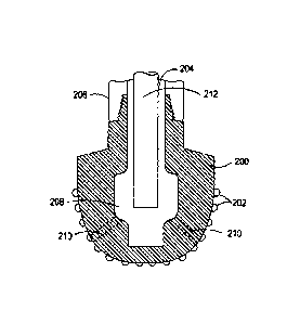
FIGS.
2A and 28, illustrated are top and cross-sectional views, respectively, of an
exemplary impregnated drill bit 200. The drill bit 200 may be used for
triggering
detonation via cavitation. The drill bit 200 has cutting surfaces 202 for
removing
rock from the bottom of a borehole. Drilling fluid flows through the interior
passage 204 (FIG. 2B) of the drill string 206 and into a cavity 208 defined
within
the drill bit 200 before exiting the drill bit 200 through various ports 210
defined
in the head of the bit 200. As illustrated in FIG. 2B, a sonicator 212 may
extend
into the cavity 208 of the drill bit 200 and may be capable of producing
cavitation in the drilling fluid passing through the cavity 208. The location
of the
sonicator 212 within cavity 208, the composition of the encapsulated
explosive,
and the flow rate of the drilling fluid may be manipulated such that
triggering
the encapsulated explosives occurs within the cavity 208, but detonation
thereof
occurs after the encapsulated explosives have exited the ports 210.
[0023] In some instances, the
sonicator 212 may be replaced with a
laser or other device that produces electromagnetic radiation of a desired
frequency. Accordingly, the drill bit 200 may equally be useful for thermal
triggering of the encapsulated explosive. One skilled in the art, with the
benefit
of this disclosure, should recognize the plurality of ways to implement these
triggering devices in the impregnated drill bit 200 or any other downhole
cutting
tool.
[0024] Referring now to FIG.
3, illustrated is an exemplary reamer
314. As illustrated, the reamer 314 may include a body 316 coupled to a stem
318. The body 316 may include one or more blocks 320 and/or one or more legs
322 coupled thereto or otherwise formed thereon. In the illustrated embodiment
of FIG. 3, the reamer 314 includes four blocks 320 and four legs 322 disposed
radially around the body 316, for example, in alternating fashion. However,
the
reamer 314 alternatively may include any number of blocks 320 and legs 322, in
any combination, as required by a particular application. The blocks 320 may
be,
for example, stabilizers or gauge pads, or they may include cutting elements,
such as PDC cutters. In some embodiments, the blocks 320 may include
hardware 324 capable of triggering detonation of the encapsulated explosive
(e.g., sonicators, lasers, or other devices that produce electromagnetic
radiation
a desired frequency).
6
CA 02917846 2016-01-08
WO 2015/030732 PCT/US2013/056839
[0025] Each leg 322 may
include a head 326, which may include
bearings, seals, or other components for supporting cutting elements, such as
a
roller cone 328, for reaming a wellbore. The stem 318 may include one or more
fluid orifices 330 and/or a downhole connector 332 for coupling the reamer 314
to other components in a drilling or reaming system, such as a pilot bit 334
or
other drilling equipment. The connector 332 may include threads, holes, pins,
profiles, or like components, as required by a particular application. In the
exemplary embodiment of FIG. 3, the pilot bit 334 is depicted as a hybrid bit,
but it is to be understood that the pilot bit 334 may be any bit required by a
particular application, such as a PDC bit, an impregnated bit, or a roller
cone bit.
In some instances, the pilot bit 334 may be include hardware capable of
triggering the encapsulated explosives, such as the hardware described above
relative to FIGS. 2A and 2B (e.g., sonicators, lasers, etc.).
[0026] One of ordinary skill
in the art, with the benefit of this
disclosure, would recognize the plurality of other configurations for
including
hardware capable of triggering detonation. For example, the hardware may be
between the reamer 314 and the pilot bit 334 and coupled to the connector 332
of FIG. 3. In another example, the hardware may be coupled to a stabilizer
(not
shown) that is coupled to a drill bit 200 (FIGS. 2A and 2B), a pilot bit 334,
a
reamer 314, or a connector 332, or other similar downhole cutting tool or
portion thereof.
[0027] In some instances, the
encapsulated explosives may be in
the drilling fluid when the drilling fluid is introduced into a wellbore. In
other
instances, the encapsulated explosives may be added to the drilling fluid at a
point along the drill string. For example, FIG. 4 illustrates a cross-section
of a
portion of a drill string 406 coupled to an impregnated drill bit 400 where
the
drill string 406 is configured to add encapsulated explosives to the drilling
fluid
circulating therethrough at one or more points along the drill string 406. The
drill
string 406 may include one or more reservoirs 436 (two shown) arranged
upstream from the impregnated drill bit 400, which may alternatively be any
other downhole cutting tool. The reservoirs 436 may contain a plurality of
encapsulated explosives 438 and may be signaled to release the encapsulated
explosives 438 into the drilling fluid via a communication line 440, or other
suitable communication method (e.g., acoustic telemetry, electromagnetic
telemetry, radio waves, electronic signaling, etc.). Upon receiving a
7
CA 02917846 2016-01-08
WO 2015/030732 PCT/US2013/056839
predetermined signal, the reservoir 436 may be configured to release at least
some of the encapsulated explosives 438 into the drilling fluid flowing
through
the drill string 406. The encapsulated explosives 438 may be triggered by any
of
the methods described herein.
[0028] In some instances, the
drill string 406 coupled to the
impregnated drill bit 400 illustrated in FIG. 4 may be useful in chemical
triggering where the reservoir 436 contains the chemical trigger (e.g., acids,
bases, salts, and the like) or one of the two encapsulated components of a
binary explosive composition. As will be appreciated, using the reservoir(s)
may
advantageously mitigate the risk of premature explosion of the encapsulated
explosives in the drill string upstream of the downhole cutting tool.
[0029] Referring again to FIG.
3, with continued reference to FIG. 4,
portions of the hardware 324 arranged on the reamer 314 may be replaced with
a reservoir similar to the reservoir 436 of FIG. 4. Again, using the reservoir
436
may advantageously allow further mitigation of the risk of premature
explosion.
[0030] In some embodiments,
the detonation of encapsulated
explosives may be intermittent relative to the drilling operation. For
example,
the encapsulated explosives may be added to the drilling fluid intermittently
(e.g., prior to introduction into the wellbore or from a reservoir). In
another
example, triggering detonation of the encapsulated explosives may be
performed intermittently, wherein the encapsulated explosives are present in
the
drilling fluid when triggering is not being performed. In some instances, a
hybrid
of the two may be performed. Intermittent use and/or triggering of the
encapsulated explosives may further mitigate risks associated with their use.
[0031] In some embodiments,
while drilling a wellbore penetrating a
subterranean formation, the encapsulated explosives may be implemented (e.g.,
included in the drilling fluid, triggered, or both) relative to select
lithologies
found within the subterranean formation, so as to complement drilling through
the lithology. In some instances, detecting the lithology may be accomplished
via one or more sensors arranged adjacent a downhole cutting tool (e.g., on a
bottom hole assembly, etc.), a drill string, or the like. In another example,
the
torque, rate of penetration, wellbore pressure, and other parameters used for
drilling may indicate that a particular lithology has been encountered where
implementation of encapsulated explosives may be useful. In yet another
example, seismic data and other formation data (e.g., core samples or drilling
8
CA 02917846 2016-01-08
WO 2015/030732 PCT/1JS2013/056839
history of a wellbore into the same formation) may be utilized in identifying
the
select lithologies. In another example, a logging/measurement while drilling
system may autonomously send signals or otherwise communicate to trigger the
encapsulated explosive (or release the encapsulated explosives) based on the
information about the subterranean formation determined from the
logging/measurement activity of the drilling system. In some embodiments,
combinations of the foregoing methods may be used for determining when to
implement the encapsulated explosives.
[0032] Embodiments disclosed herein include:
A: a method that includes drilling a wellbore penetrating a
subterranean formation with a downhole cutting tool; circulating a drilling
fluid in
the wellbore, wherein the drilling fluid comprises a base fluid and an
encapsulated explosive having an average diameter of about 10 nm to about 20
microns; triggering detonation of the encapsulated explosive; and detonating
the
encapsulated explosive proximal to a portion of the subterranean formation
adjacent the downhole cutting tool;
B: a method that includes drilling a wellbore penetrating a
subterranean formation with a downhole cutting tool operably coupled to a
drill
string and a reservoir being coupled to at least one selected from the group
consisting of the downhole cutting tool and the drill string, wherein the
reservoir
contains a plurality of encapsulated explosives; circulating a drilling fluid
in the
wellbore; releasing at least a portion of the encapsulated explosives from the
reservoir and into the drilling fluid, the encapsulated explosives having an
average diameter of about 10 nm to about 20 microns; triggering detonation of
the encapsulated explosives in the drilling fluid; and detonating the
encapsulated
explosives proximal to a portion of the subterranean formation adjacent the
downhole cutting tool; and
C: a method that includes drilling a wellbore penetrating a
subterranean formation with a downhole cutting tool operably coupled to a
drill
string and a reservoir being coupled to at least one of the downhole cutting
tool
and the drill string, wherein the reservoir contains a plurality of first
encapsulated components; circulating a drilling fluid in the wellbore, the
drilling
fluid comprising a base fluid and a plurality of second encapsulated
components,
wherein the first and second pluralities of encapsulated components form part
of
a binary explosive; releasing at least a portion of the first encapsulated
9
CA 02917846 2016-01-08
WO 2015/030732 PCT/US2013/056839
components from the reservoir into the drilling fluid; triggering detonation
of the
binary explosive by comingling the first encapsulated components with the
second encapsulated components; and detonating the binary explosive proximal
to a portion of the subterranean formation adjacent the downhole cutting tool.
[0033] Each of embodiments A,
B, and C may have one or more of
the following additional elements, unless otherwise provided for, in any
combination: Element 1: wherein triggering detonation of the encapsulated
explosive comprises irradiating the encapsulated explosive with
electromagnetic
radiation having a frequency of about 1.06 Hz to about 1017 Hz; Element 2:
wherein triggering detonation of the encapsulated explosive comprises crushing
the encapsulated explosive between the downhole cutting tool and the
subterranean formation; Element 3: wherein triggering detonation of the
encapsulated explosive comprises introducing cavitation into the drilling
fluid;
Element 4: wherein triggering detonation of the encapsulated explosive
comprises contacting the encapsulated explosive with a chemical trigger;
Element 5: wherein triggering detonation of the encapsulated explosive is
intermittent; Element 6: triggering detonation of the encapsulated explosive
occurs upstream of the drill bit in a drill string coupled to the downhole
cutting
tool; Element 7: wherein the encapsulated explosive comprises at least one
selected from the group consisting of a liposome, a crosslinked liposome, a
nanoliposome, a polymeric vesicle, a dendritic polymer, a coated nanoparticle,
a
coated microparticle, an impregnated nanoparticle, an impregnated
microparticle, and any hybrid thereof; Element 8: wherein the encapsulated
explosive comprises at least one selected from the group consisting of
thermite,
octogen, pentaerythritol tetranitrate, tetranitrotoluene, an explosive
nitroamine,
lead picrate, mercury fulminate, nitrogen triiodide, potassium perchlorate,
ammonium perchlorate, and the like, and a combination thereof; Element 9:
wherein the encapsulated explosive comprises a first encapsulated explosive
and
a second encapsulated explosive, and wherein the first encapsulated explosive
has a higher sensitivity to detonation than the second encapsulated explosive;
Element 10: wherein the encapsulated explosive is a binary explosive
comprising
two components that are each encapsulated individually; Element 11: wherein
the encapsulated explosive is a binary explosive comprising two components
that are each encapsulated individually, and wherein the two components
comprise at least one pair selected from the group consisting ammonium
=
CA 02917846 2016-01-08
WO 2015/030732 PCT/US2013/056839
nitrate/fuel oil, ammonium nitrate/nitromethane, ammonium nitrate/aluminum,
and nitroethane/physical sensitizer; and Element 12: wherein the encapsulated
explosive has an average diameter of about 10 nm to about 500 nm.
[0034] By way of non-limiting
example, exemplary combinations
applicable to A, B, C include: at least two of Elements 1-4; Element 5 in
combination with at least one of Elements 1-4; Element 6 in combination with
at
least one of Elements 1-4; Element 5 in combination with Element 6; Element 5
in combination with Element 6 and at least one of Elements 1-4; at least two
of
Elements 7-11; Element 5 in combination with at least one of Elements 7-11;
Element 6 in combination with at least one of Elements 7-11; Element 5 in
combination with Element 6 and at least one of Elements 7-11; Element 12 in
combination with one of the foregoing combinations; Element 5 in combination
with Element 12; and Element 6 in combination with Element 12.
[0035] One or more
illustrative embodiments incorporating the
principles of the disclosure described herein are presented below. Not all
features of an actual implementation are described or shown in this
application
for the sake of clarity. It is understood that in the development of an actual
embodiment incorporating the present disclosure, numerous implementation-
specific decisions must be made to achieve the developer's goals, such as
compliance with system-related, business-related, government-related and other
constraints, which vary by implementation and from time to time. While a
developer's efforts might be complex and time-consuming, such efforts would
be, nevertheless, a routine undertaking for those of ordinary skill the art
having
benefit of this disclosure.
[0036] It should be noted that
when the term "about" is provided
herein at the beginning of a numerical list, the term modifies each number of
the
numerical list. In some numerical listings of ranges, some lower limits listed
may
be greater than some upper limits listed. One skilled in the art will
recognize that
the selected subset will require the selection of an upper limit in excess of
the
selected lower limit. Unless otherwise indicated, all numbers expressing
quantities of ingredients, properties such as molecular weight, reaction
conditions, and so forth used in the present specification and associated
claims
are to be understood as being modified in all instances by the term "about."
Accordingly, unless indicated to the contrary, the numerical parameters set
forth
in the following specification and attached claims are approximations that may
11
CA 02917846 2016-01-08
WO 2015/030732 PCT/US2013/056839
vary depending upon the desired properties sought to be obtained by the
exemplary embodiments described herein. At the very least, and not as an
attempt to limit the application of the doctrine of equivalents to the scope
of the
claim, each numerical parameter should at least be construed in light of the
number of reported significant digits and by applying ordinary rounding
techniques.
[0037] Therefore, the present disclosure is well adapted to attain the
ends and advantages mentioned as well as those that are inherent therein. The
particular embodiments disclosed above are illustrative only, as the present
disclosure may be modified and practiced in different but equivalent manners
apparent to those skilled in the art having the benefit of the teachings
herein.
Furthermore, no limitations are intended to the details of construction or
design
herein shown, other than as described in the claims below. It is therefore
evident that the particular illustrative embodiments disclosed above may be
altered, combined, or modified and all such variations are considered within
the
scope and spirit of the present disclosure. The disclosure illustratively
described
herein suitably may be practiced in the absence of any element that is not
specifically disclosed herein and/or any optional element disclosed herein.
While
compositions and methods are described in terms of "comprising," "containing,"
or "including" various components or steps, the compositions and methods can
also "consist essentially of" or "consist of" the various components and
steps. All
numbers and ranges disclosed above may vary by some amount. Whenever a
numerical range with a lower limit and an upper limit is disclosed, any number
and any included range falling within the range is specifically disclosed. In
particular, every range of values (of the form, "from about a to about b," or,
equivalently, "from approximately a to b," or, equivalently, "from
approximately
a-b") disclosed herein is to be understood to set forth every number and range
encompassed within the broader range of values. Also, the terms in the claims
have their plain, ordinary meaning unless otherwise explicitly and clearly
defined
by the patentee. Moreover, the indefinite articles "a" or "an," as used in the
claims, are defined herein to mean one or more than one of the element that it
introduces. If there is any conflict in the usages of a word or term in this
specification and one or more patent or other documents that may be
incorporated herein by reference, the definitions that are consistent with
this
specification should be adopted.
12