Note: Descriptions are shown in the official language in which they were submitted.
CA 02917979 2016-01-11
WO 2015/004264 PCT/EP2014/064884
1
DEVICE FOR USE IN THE DETECTION OF BINDING AFFINITIES
The present invention relates to a device for use in the
detection of binding affinities as well as to a method in
accordance with the respective independent claim.
Such devices are used, for example, as biosensors in a large
variety of applications. One particular application is the
detection or monitoring of binding affinities or processes.
For example, with the aid of such biosensors various assays
detecting the binding of target samples to binding sites can
be performed. Typically, large numbers of such assays are
performed on a biosensor at spots which are arranged in a
two-dimensional microarray on the surface of the biosensor.
The use of microarrays provides a tool for the simultaneous
detection of the binding affinities or processes of different
target samples in high-throughput screenings. For detecting
the affinities of target samples to bind to specific binding
sites, for example, the affinity of target molecules to bind
to specific capture molecules, a large number of capture
molecules are immobilised on the outer surface of the
biosensor at individual spots (e.g. by ink-jet spotting or
photolithography). Each spot forms an individual measurement
zone for a predetermined type of capture molecule. The
binding of a target molecule to a specific type of capture
molecule is detected and is used to provide information on
the binding affinity of the target molecule with respect to
the specific capture molecule.
A known technique for detecting binding affinities of target
samples utilizes fluorescent labels. The fluorescent labels
CA 02917979 2016-01-11
WO 2015/004264 PCT/EP2014/064884
- 2 -
are capable of emitting fluorescent light upon excitation.
The emitted fluorescent light has a characteristic emission
spectrum which identifies the present fluorescent label at a
particular spot. The identified fluorescent label indicates
that the labelled target molecule has bound to the particular
type of binding sites present at this spot.
A sensor for detecting labelled target samples is described
in the article "Zeptosens' protein microarrays: A novel high
performance microarray platform for low abundance protein
analysis", Proteomics 2002, 2, S. 383-393, Wiley-VCH Verlag
GmbH, 69451 Weinheim, Germany. The sensor described there
comprises a planar waveguide arranged on a substrate. The
planar waveguide has an outer surface capable of attaching a
plurality of binding sites thereon. Moreover, the planar
waveguide has a plurality of incoupling lines for coupling a
beam of coherent light into the planar waveguide in a manner
such that a beam of coherent light propagates along the
planar waveguide. The coherent light propagates through the
planar waveguide under total reflection with an evanescent
field of the coherent light propagating along the outer
surface of the planar waveguide. The depth of penetration of
the evanescent field into the medium of lower refractive
index at the outer surface of the planar waveguide is in the
order of magnitude of a fraction of the wavelength of the
coherent light propagating through the planar waveguide. The
evanescent field excites the fluorescent labels of the
labelled target samples bound to the binding sites arranged
on the surface of the planar waveguide. Due to the very small
depth of penetration of the evanescent field into the
optically thinner medium at the outer surface of the planar
waveguide, only the labelled samples bound to the binding
CA 02917979 2016-01-11
WO 2015/004264 PCT/EP2014/064884
- 3 -
sites immobilized on the outer surface of the planar
waveguide are excited. The fluorescent light emitted by these
labels is then detected with the aid of a CCD camera.
While it is principally possible to detect the binding
affinities using fluorescent labels, this technique is
disadvantageous in that the detected signal is produced by
the fluorescent labels rather than by the binding partners
themselves. In addition, labelling the target samples
requires additional preparation steps. Moreover, labelled
target samples are comparatively expensive. Another
disadvantage is the falsification of the results caused by
steric hindrance of the fluorescent labels at the target
sample which might interfere with the binding of the target
samples to the capture molecules. Further disadvantages are
the falsification of the results due to photobleaching of the
labels or quenching effects.
It is an object of the present invention to provide a device
for use in the detection of binding affinities between a
target sample and a binding site as well as a method capable
of providing a signal representative for the binding
affinities which overcome or at least greatly reduce the
disadvantages of the prior art described above.
In accordance with the invention, this object is achieved by
a device for use in the detection of binding affinities. The
device comprises a planar waveguide arranged on a substrate.
The planar waveguide has an outer surface and a plurality of
incoupling lines for coupling a beam of coherent light into
the planar waveguide in a manner such that in operation a
parallel beam of coherent light propagates along the planar
CA 02917979 2016-01-11
WO 2015/004264 PCT/EP2014/064884
- 4 -
waveguide with an evanescent field propagating along the
outer surface thereof. The plurality of incoupling lines are
curved and arranged to have an increasing distance between
adjacent incoupling lines when viewed in the direction of
propagation of the parallel beam of coherent light along the
planar waveguide, the arrangement of the plurality of
incoupling lines and the distance bewtween adjacent
incoupling lines being such that in operation a divergent
beam of coherent light of a predetermined wavelength coming
from a predetermined first focal location and impinging on
the plurality of incoupling lines is coupled into the planar
waveguide in a manner such that the parallel beam of coherent
light propagates along the planar waveguide. A plurality of
binding sites capable of binding a target sample is attached
to the outer surface. The attached binding sites are arranged
along at least one further plurality of diffraction lines
arranged in an outcoupling section of the planar waveguide.
The at least one further plurality of diffraction lines
comprises a plurality of curved outcoupling lines which are
arranged to have a decreasing distance between adjacent
curved outcopuling lines when viewed in the direction of
propagation of the coherent light impinging thereon so as to
be capable of diffracting a portion of the coherent light of
the predetermined wavelength to decouple it from the planar
waveguide in a manner such that the decoupled portion of
coherent light of the predetermined wavelength converges into
a predetermined second focal location to provide at the
second focal location a signal representative of the binding
affinity between the binding sites and the target sample.
It is to be noted that the term "curved outcoupling lines"
comprises both, "real" lines having an optically diffracting
CA 02917979 2016-01-11
WO 2015/004264 PCT/EP2014/064884
- 5 -
effect (physically present lines, e.g. the lines of an
optical grating) and diffracting a portion of the coherent
light of the predetermined wavelength to the predetermined
second focal location (in this case the binding sites are
arranged along a further plurality of "virtual" lines to form
a biological grating together with the target samples, in
order to diffract a portion of the parallel beam of coherent
light towards the "real" lines), as well as "virtual" lines
(lines which may not be physically present on the outer
surface of the waveguide or which themselves do not have an
optically diffracting effect but are formed by the binding
sites arranged along these "virtual" lines to form a
biological grating together with the target sample). Both
types of "curved outcopuling lines", the "real" lines as well
as the "virtual" lines diffract a portion of the coherent
light of the predetermined wavelength to the predetermined
second focal location. In the latter case, i.e. when the
curved outcoupling lines are formed by the "virtual" lines of
the biological grating, "real" lines such as those of an
optical grating may or may not be present in addition to the
biological grating.
The term "curved incoupling lines" also comprises both "real"
lines having an optically diffracting effect (physically
present lines, e.g. the lines of an optical grating) and
diffracting a portion of the coherent light of the
predetermined wavelength to couple the diffracted portion of
coherent light into the planar waveguide as well as "virtual"
lines (lines which may not be physically present on the outer
surface of the waveguide or which themselves do not have an
optically diffracting effect but are formed by binding sites
arranged along these "virtual" lines to form a biological
CA 02917979 2016-01-11
WO 2015/004264 PCT/EP2014/064884
- 6 -
grating together with the target sample). The "real" lines
may for example be embodied as curved physical lines which
couple a divergent beam of coherent light into the waveguide,
whereas "virtual" lines may be curved lines which couple a
divergent beam of coherent light into the planar waveguide,
with binding sites being arranged along these virtual lines
to diffract (together with the target sample bound thereto) a
portion of a divergent beam of coherent light coming from a
point light source (arranged at a predetermined location) and
to couple the diffracted portion of the coherent light into
the planar waveguide. The curved incoupling lines ("real"
lines or "virtual" lines) have an inreasing distance from one
another when viewed in the direction of propagation of the
coherent light coupled into the planar wavguide. It is thus
possible, that both the incoupling lines and the outcoupling
lines may comprise only biological gratings (no "real"
lines). This may be advantageous with regard to the
manufacture of such gratings, since manufacture of both the
incoupling lines and the outcoupling lines can then be
performed in a single step using lithography techniques. This
may lead to less expensive manufacture of the gratings.
In operation, coherent light which has been diffracted in the
outcopuling section at attached binding sites bound to the
applied target sample (together forming the biological
grating) can be provided at the second focal location as a
measure for the binding affinity. For example, the intensity
of the coherent light provided at the predetermined second
focal location is detected and compared to a known intensity
of coherent light which has been diffracted by the binding
sites only (without having appliedthe target sample). The
change in intensity is representative of (i.e. is a measure
CA 02917979 2016-01-11
WO 2015/004264 PCT/EP2014/064884
- 7 -
for) the binding affinity between the binding sites and the
target sample since the intensity at the predetermined second
focal location is significantly different as target sample
has bound to the binding sites when compared to the intensity
at the predetermined second focal location caused by the
binding sites only. This overcomes the need for labelling the
target samples since the outcoupled portion of the coherent
light constructively interferes at the predetermined second
focal location to provide a detectable signal.
"Constructively interferes at the predetermined second focal
location" means in other words that the coherent light
converging into the predetermined second focal location at
the said predetermined second focal location has a difference
in optical path length which is an integer multiple of the
predetermined wavelength. This interference maximum at the
predetermined second focal location provides a detectable
signal originating from the binding sites bound to the target
sample.
In general, "binding sites" are locations on the outer
surface of the planar waveguide to which a target sample may
bind (or binds in case of binding affinity). The detection of
binding affinities according to the invention is neither
limited to specific types of target samples nor to any type
of binding sites, but rather the binding characteristics of
e.g. molecules, proteins, DNA etc. as target samples can be
analysed with respect to any suitable type of binding sites
on the planar waveguide. Technically, the term "diffracted"
denotes the interference of the coherent light of the
evanescent field which already has interacted with target
samples bound to the binding sites. The term diffracted
"portion" refers to the fact, that not the entire light is
CA 02917979 2016-01-11
WO 2015/004264 PCT/EP2014/064884
- 8 -
diffracted for decoupling from the waveguide so that a
portion (in fact the main portion) of the parallel beam of
coherent light continues to propagate along the planar
waveguide. The term "parallel beam" explicitly includes some
deviations according to which the light propagates in a
converging or diverging manner in the waveguide. The extent
of those deviations is limited by the intensity of the
detected signal so that parallel includes deviations which
allow for providing at the second focal location a signal
representative of the binding affinity between the binding
sites and the target sample. Because of the reversibility of
the optical path of the coherent light, the roles of the
incoupling lines and the outcoupling lines can be generally
exchanged, resulting in analoguous functions of the
embodiments described in the invention. The binding sites may
be arranged at more than one plurality of lines. The
arrangement of the binding sites along the lines represents
the optimum case in which all binding sites are exactly
arranged on the ideal line. The optimum arrangement of the
binding sites is associated with a maximum signal at the
second focal location, but in practice, the arrangement of
the binding sites will deviate to some extent from such
optimum arrangement while the decoupled portion of the
parallel beam of coherent light converging into the second
focal location is still present. The plurality of incoupling
lines and the plurality of curved outcoupling lines are
arranged on the outer surface of the planar waveguide in a
manner such that their locations in xj,yi-coordinates are
geometrically defined by the equation
xN(Ao+j) 4nS(N2-1-1)(17-Pf 2) + (nsX)2(A0-Pi)2
x- _______________ 2 2
N ¨ns
CA 02917979 2016-01-11
WO 2015/004264 PCT/EP2014/064884
- 9 -
wherein
A is the vacuum wavelength of the propagating light ,
N is the effective refractive index of the guided mode in
the planar waveguide; N depends on the thickness and
the refractive index of the planar waveguide, the
refractive index of the substrate, the refractive index
of a medium on the outer surface of the planar
waveguide and the polarization of the guided mode,
ns is the refractive index of the substrate,
f is the distance (focal length) between the focal
location and the outer surface of the planar waveguide,
Ao is an integer which is chosen to be close to nsf/A, and
j is a running integer that indicates the index of the
respective line.
The chosen integer Ao assigns negative x-values at the centre
of the lines to negative j values and positive x-values at
the centre of the lines with positive j values. Or to say it
in other words, the integer Ao defines the origin of the x,y-
coordinates frame that is used for the location of the lines
at the outer surface of the planar waveguide; the chosen Ao
value allocates the detection location at x=0, y=0, z=-f.
The first focal location and the second focal location are in
a preferred example of a diameter of approximately 0.5 pm and
are arranged at a distance of between 10-200 pm.
According to one aspect, the plurality of incoupling lines is
arranged at a first surface portion of the outer surface of
the planar waveguide and the plurality of curved outcoupling
lines is arranged at a second surface portion of the outer
surface of the planar waveguide. The first surface portion
CA 02917979 2016-01-11
WO 2015/004264 PCT/EP2014/064884
- 10 -
includes a blank section in which there are no lines and the
second surface portion includes a further blank section in
which there are no lines. The blank section is formed to
avoid a 2'd order Bragg reflection (an interference maximum
of coherent light diffracted at the respective plurality of
lines which emerges in the planar waveguide), or similar
optical effects, which potentially impair the overall
intensity of the detected signal. Preferably, the first
surface portion and the second surface portion are of a
diameter of 25-300 pm.
According to another aspect, the first surface portion and
the second surface portion are arranged spatially separated
at the outer surface of the planar waveguide. The spatially
separated arrangement allows for diffracting a maximal
portion of the evanescent field of the parallel beam of
coherent light (incoupled by all lines of the plurality of
incoupling lines) at every line of the plurality of curved
outcoupling lines.
According to an alternative aspect, the first surface portion
and the second surface portion are arranged at the outer
surface of the planar waveguide to at least partially overlap
in a manner such that the blank section and the further blank
section form a common blank section. In the at least
partially overlapping arrangement, a minimal area of the
outer surface of the planar waveguide is covered by said
first and second surface portions. The reduced size of the
covered area allows to arrange a higher number of such first
and second surface portions at the outer surface of the
planar waveguide.
CA 02917979 2016-01-11
WO 2015/004264 PCT/EP2014/064884
- 11 -
According to a further aspect, the first surface portion and
the second surface portion are of the same size.
According to an alternative aspect, the at least one further
plurality of diffraction lines arranged in the outcoupling
section further comprises a plurality of straight lines. The
straight lines run parallel to one another with a constant
distance between adjacent straight lines and are arranged at
an angle 13 relative to the direction of propagation of the
parallel beam of coherent light in a manner such that a
portion of the parallel beam of coherent light is diffracted
under a diffraction angle a relative to the straight lines
such that the diffracted portion of the parallel beam of
coherent light impinges onto the plurality of curved
outcoupling lines. The attached binding sites are arranged
along the plurality of straight lines or along the plurality
of curved outcoupling lines.
The direction of propagation of the parallel beam of coherent
light is defined as starting from the plurality of incoupling
lines and extending in the direction in which the coherent
light is coupled into the planar waveguide which is usually
close to a direction perpendicular to the plurality of
incoupling lines. The coherent light diffracted at the
binding sites bound to target samples impinges onto the
plurality of curved outcoupling lines of the second surface
portion under the diffraction angle a relative to the
straight lines. Under the diffraction angle a, the light
coming from the plurality of straight lines constructively
interferes (i.e. light diffracted at different straight lines
has a difference in optical path length of an integer
multiple of the predetermined wavelength) at the plurality of
CA 02917979 2016-01-11
WO 2015/004264 PCT/EP2014/064884
- 12 -
curved outcoupling lines. The diffraction angle a depends on
the constant distance between adjacent predetermined straight
lines taking into account the predetermined wavelength and
the refractive indices of the substrate, of the planar
waveguide and of the medium at the outer surface (e.g. the
medium at the outer surface may comprise the target samples)
of the planar waveguide.
According to one aspect, the plurality of curved outcoupling
lines is arranged at the outer surface in a partition of the
planar waveguide through which the portion of the parallel
beam of coherent light diffracted at the straight lines
propagates, and through which no other light of the parallel
beam of coherent light propagates. This allows to detect the
light at the second focal location with a reduced background
signal because the second focal location is located normal
to an area of the outer surface of the planar waveguide
through which no other "non-diffracted" light of the parallel
beam of coherent light propagates.
According to another aspect, a surface coating layer is
arranged on top of the outer surface of the planar waveguide.
The surface coating layer has a porous internal structure to
allow the target sample applied to the cotaing layer to
diffuse therethrough to reach the binding sites attached to
the outer surface of the planar waveguide. Advantageously,
the target sample can be applied in a mixture comprising
other compounds as well but only the target sample is capable
of diffusing through the porous internal structure of the
coating layer to reach the outer surface of the planar
waveguide.
CA 02917979 2016-01-11
WO 2015/004264 PCT/EP2014/064884
- 13 -
In another aspect, the invention relates to a method for the
detection of binding affinities, the method comprising the
steps of:
- providing a device as described herein,
- applying to the outcoupling section of the planar
waveguide along the at least one further plurality of
diffraction lines where the binding sites are arranged a
target sample for which the binding affinity between the
binding sites and the target sample is to be detected,
- generating at the predetermined first focal location a
divergent beam of coherent light in a manner so as to impinge
on the plurality of incoupling lines of the planar waveguide
to couple the divergent beam of coherent light into the
planar waveguide in a manner such that the beam of coherent
light coupled into the planar waveguide propagates as a
parallel beam of coherent light along the planar waveguide
with an evanescent field of the parallel beam of coherent
light propagating along the outer surface thereof, wherein a
portion of the coherent light is diffracted by the plurality
of curved outcoupling lines of the outcoupling section of the
planar waveguide to decouple it from the planar waveguide in
a manner such that the decoupled portion of the coherent
light converges into the second predetermined focal location,
and
- detecting the decoupled portion of coherent light at
the second predetermined focal location as a signal
representative of the binding affinity between the binding
sites and the target sample.
According to an aspect of the method, the decoupled portion
of the parallel beam of coherent light is detected in a
detection zone having a predetermined size and being arranged
CA 02917979 2016-01-11
WO 2015/004264 PCT/EP2014/064884
- 14 -
to include the second predetermined focal location to
determine that location in the detection zone, where the
decoupled portion of coherent light of the predetermined
wavelength has a relative maximum intensity. The location of
the relative maximum intensity is defined as the second
predetermined focal location. The relative maximum intensity
allows to find the detectable signal in the detection zone.
The size of the detection zone depends on the manufacturing
tolerances of the planar waveguide having a typical thickness
in the range of 100 nm to 300 nm; a typical manufacturing
tolerance of the waveguide thickness is a few nanometers.
This tolerance corresponds to a lateral extension of the
detection zone in the order of a few percent of the lateral
extension of the outcoupling section.
According to another aspect of the method, the divergent beam
of coherent light is successively generated at different
locations in a beam generation zone having a predetermined
size and being arranged to include the first predetermined
focal location. For each successively generated beam of
coherent light that location in the detection zone having the
relative maximum intensity of the decoupled portion of the
parallel beam of coherent light is determined, defining that
location in the detection zone where the relative maximum
intensity is highest as the second predetermined focal
location, and defining that location in the beam generation
zone, where the corresponding beam is generated as the first
predetermined focal location. Advantageously, defining the
first predetermined focal location for which the relative
maximum intensity is highest allows to find the absolute
maximum intensity as the best detectable signal at the second
predetermined focal location. This is of advantage because
CA 02917979 2016-01-11
WO 2015/004264 PCT/EP2014/064884
- 15 -
different planar waveguides usually have a different
thickness, e.g. in case of manufacturing tolerances, which
may lead to different locations of the first and second
predetermined focal locations for each device. The exact
location of both predetermined focal locations can be found
in this manner. The size of the beam generation zone and of
the detection zone depends on the magnitude of manufacturing
tolerances.
In the following two preferred alternative embodiments of the
method according to the invention are explained. Both
embodiments relate to the detection of binding affinities by
using the first, respectively, the second embodiment of the
device showing manufacturing tolerances.
In the first alternative of the method, the beam generation
zone is an area in a first plane parallel to the outer
surface of the planar waveguide. The detection zone is a
straight line extending parallel to the direction of
propagation of the parallel beam of coherent light in a
second plane parallel to the outer surface of the planar
waveguide. This allows to detect binding affinities by using
a device according to the first embodiment. The working
principle and the advantages thereof are discussed in detail
below with reference to Fig. 7 so as to avoid uneccessary
iteration here.
In the second alternative of the method, the beam generation
zone is an area in a first plane parallel to the outer
surface of the planar waveguide. The detection zone is an
area in a second plane parallel to the outer surface of the
planar waveguide. This allows for detecting the decoupled
CA 02917979 2016-01-11
WO 2015/004264 PCT/EP2014/064884
- 16 -
portion of the parallel beam of coherent light at the second
predetermined focal location of a device according to the
second embodiment in which the outcoupling section
additionally comprises a plurality of straight lines. The
working principle and advantages are explained in detail with
reference to Fig. 8 so as to avoid uneccessary iteration
here.
Further advantageous aspects of the invention become apparent
from the following description of embodiments of the
invention with reference to the accompanying drawings in
which:
Fig. 1 shows a perspective view of a device according to
a first embodiment of the invention with a first
surface portion and a second surface portion
arranged spatially separated at an outer surface
of the planar waveguide;
Fig. 2 shows a perspective view of a device according to
a second embodiment of the invention with the
first surface portion and the second surface
portion arranged at the outer surface of the
planar waveguide in a manner so as to at least
partially overlap;
Fig. 3 shows a perspective view of the device of Fig. 2
with a substrate having approximately the size of
the first surface portion overlapping with the
second surface portion;
Fig. 4 shows a perspective view of the device of Fig. 3
CA 02917979 2016-01-11
WO 2015/004264 PCT/EP2014/064884
- 17 -
with a surface coating layer;
Fig. 5 shows a perspective view of a device according to
a third embodiment of the invention with the
outcoupling section further comprising a
plurality of straight lines;
Fig. 6 shows a first embodiment of a system for using a
device for use in the detection of binding
affinities;
Fig. 7 shows the device of Fig. 1 with different first
focal locations arranged in a beam generation
zone and different second focal locations
arranged in a detection zone forming a straight
line in the plane parallel to the outer surface
of the planar waveguide;
Fig. 8 shows the device of Fig. 5 with different first
focal locations arranged in a beam generation
zone and different second focal locations
arranged in a detection zone forming an area in
the plane parallel to the outer surface of the
planar waveguide; and
Fig. 9 shows the system of Fig. 6 comprising a first
partial beam stop and a second partial beam stop.
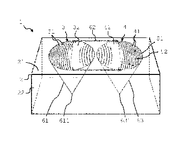
A first embodiment of the device 1 according to the invention
is shown in Fig. 1 in a perspective view. A planar waveguide
2 is arranged on top of a substrate 22 and comprises an outer
surface 21 at the upper side thereof. Outer surface 21 of the
CA 02917979 2016-01-11
WO 2015/004264 PCT/EP2014/064884
- 18 -
planar waveguide comprises a plurality of incoupling lines 31
arranged in a first surface portion 3 and a plurality of
curved outcoupling lines 41 arranged in a second surface
portion 4. The plurality of curved outcoupling lines 41
comprise binding sites 51 to some of which a target sample 52
has bound.
The plurality of incoupling lines 31 are curved and arranged
to have an increasing distance between adjacent incoupling
lines 31 (from left to right). The curvature and the
increasing distance between adjacent lines is chosen to allow
for coupling a divergent beam of coherent light 61 coming
from a first focal location 611 into the planar wavguide,
with the first focal location 611 being arranged in the shown
example at the lower side of the substrate 22. The generation
of such divergent beam of coherent light 61 is explained for
the system described below with reference to Fig. 6. The
divergent beam of coherent light 61 (or a portion thereof) is
coupled into the planar waveguide 2 by the plurality of
incoupling lines 31 which act as an optical grating having a
plurality of grating lines (e.g. grooves, elongated
protrusions, periodical changes of a refractive index of the
planar waveguide). The coupling of divergent beam of coherent
light 61 into the planar waveguide 2 causes the parallel beam
of coherent light 62 to propagate along the planar waveguide
2, with a portion of the parallel beam of coherent light 62
propagating along the outer surface 21 to form an evanescent
field (not shown) in the proximity of the outer surface 21 of
the planar waveguide 2.
As already mentioned, the plurality of curved outcoupling
lines 41 comprises binding sites 51 attached to the outer
CA 02917979 2016-01-11
WO 2015/004264 PCT/EP2014/064884
- 19 -
surface 21 of the planar waveguide 2. Some of the attached
binding sites 51 are bound to target sample 52 applied to
outer surface 21 of the planar waveguide 2. The curvature of
the plurality of curved outcoupling lines 41 as well as the
arrangement of the adjacent incopuling lines having a
decreasing distance between adjacent incoupling lines 31 from
left to right is chosen to allow for decoupling the parallel
beam of coherent light 62 such that a decoupled portion of
the parallel beam of coherent light 63 converges into a
second focal location 631. Second focal location 631 is
arranged at the lower side of substrate 22. Since the
intensity of the outcoupled portion of the parallel beam of
coherent light 63 converging into second focal location 631
changes in case of binding sites 51 are bound to target
samples 52, a signal (intensity) representative to the
binding affinity between binding sites 51 and target sample
52 is provided therein.
As shown, first surface portion 3 includes a blank section 32
and second surface portion 4 includes a further blank section
42, each of which formes a surface area free of any lines.
Blank section 32 and further blank section 42 are completely
spatially separated. An alternative arrangement is discussed
in the following.
The alternative arrangement is shown in Fig. 2, blank section
32 and further blank section 42 form a common blank section
322. First surface portion 3 and second surface portion 4 are
arranged in an overlapping manner in which the plurality of
incoupling lines 31 overlap with the plurality of curved
outcoupling lines 41 such that blank section 32 and further
blank section 42 "overlap" to form common blank section 322.
CA 02917979 2016-01-11
WO 2015/004264 PCT/EP2014/064884
- 20 -
In use, the divergent beam of coherent light 61 is coupled
into the planar waveguide 2 by the plurality of incoupling
lines 31 so that a parallel beam of coherent light 62
propagates along planar waveguide 2 with an evanescent field
propagating along the outer surface 21 thereof. A portion of
the evanescent field (and thus of the beam) is diffracted at
the binding sites (not shown) bound to target samples (not
shown) which are arranged along the plurality of curved
outcoupling lines 41. A portion of the parallel beam of
coherent light 62 is thus decoupled from the planar waveguide
2 in a manner such that the outcoupled portion of parallel
beam of coherent light 63 converges into the second focal
location 631. In principle, the coherent light of the
evanescent field is diffracted at binding sites bound to
target samples so that light diffracted at the binding sites
bound to target samples arranged along each of the plurality
of curved outcoupling lines 41 constructively interferes at
the second focal location 631. First focal location 611 and
the adjacent second focal location 631 are separated by a
distance of 10 pm - 20 pm.
Fig. 3 illustrates device 1 having substrate 22 and planar
waveguide 2 arranged thereon, and having a diameter which
corresponds to the size of the first surface portion 3
overlapping with the second surface portion 4. Hence, a
compact device 1 is provided having an outer contour of a
very small diameter, in particular in the range of 25 pm to
500 pm, and preferably 300 pm.
Fig. 4 illustrates the device 1 according to another
advantageous aspect in which a surface coating layer 7 is
formed on top of the outer surface of the planar waveguide 2
CA 02917979 2016-01-11
WO 2015/004264 PCT/EP2014/064884
- 21 -
arranged on substrate 22. Surface coating layer 7, in the
present example, is made of a hydrogel that is covered by a
light absorbing (black) membrane with nanopores. These
materials have a porous internal structure having a
predetermined porosity in the range of 5% to 90% (fraction of
the volume of pores relative to the total volume) and a
predetermined pore size in the range of 10 nm to 10 pm
(average diameter of pores). This allows the applied target
sample (e.g. a specific type of molecule) to diffuse
therethrough to reach the binding sites attached to the outer
surface.
Another embodiment of the device 1 is depicted in Fig. 5 in a
top view. At the left hand side, the plurality of incoupling
lines 31 and at the right side the plurality of curved
outcoupling lines 41 are arranged. Different from the
previously described embodiments, the outcoupling section
additionally comprises a plurality of straight lines 42 which
are arranged between the incoupling lines 31 and the
outcoupling lines 41. In the present example, the binding
sites (not shown) are arranged along the plurality of
straight lines 42. The straight lines 42 are arranged to run
parallel to one another with a constant distance between
adjacent straight lines. The divergent beam of coherent light
(not shown) is coupled into the planar waveguide 2 by the
plurality of incoupling lines 31 so that a beam of coherent
light 62 (the beam of coherent light is shown in dashed lines
and the diffracted portion of the beam of coherent light is
shown as parallel arrows) propagates as a parallel beam along
planar waveguide 2 together with its associated evanescent
field. The individual lines of the plurality of straight
lines 42 are arranged at an angle 13 with respect to the
CA 02917979 2016-01-11
WO 2015/004264 PCT/EP2014/064884
- 22 -
propagation direction of the parallel beam of coherent light
62. The binding sites bound to the target samples which are
arranged along the plurality of straight lines 42 diffract a
portion of the evanescent field (and thus of the parallel
beam of coherent light), and this diffracted portion of the
beam of coherent light 62 propagates along the planar
waveguide 2 towards the plurality of curved outcoupling lines
41. The portion of the parallel beam of coherent light 62 is
diffracted under a diffraction angle a (which equals 13)
relative to the straight lines. The intensity of the
diffracted portion of the parallel beam of coherent light 62
which impinges onto the plurality of curved outcoupling lines
41 and of which a portion is decoupled from the planar
waveguide 2 provides a signal representative of the binding
affinity, as described already for the first embodiment.
Fig. 6 shows a system 10 for detecting binding affinities.
System 10 comprises a laser light source 11 which is capable
of providing at first focal location 611 of a device 1 (as
described above) a divergent beam of coherent light 61. Laser
light source 11 generates a beam of coherent light which is
focussed by focussing lens 12 into first focal location 611.
An optical scanning unit 12, 17 comprises a scanner 17 and a
focussing lens 12 and generates a divergent beam of coherent
light 61 in a beam generation zone (as is explained with
reference to Fig. 7 and 8). Divergent beam of coherent light
61 coming from the first focal location 611 is coupled into
the planar waveguide 2 and generates a decoupled portion 63
of diffracted coherent light which converges into second
focal location 631. System 10 further comprises an optical
detection unit providing a spatial filter 100 capable of
detecting the intensity of the converging beam of the
CA 02917979 2016-01-11
WO 2015/004264 PCT/EP2014/064884
- 23 -
decoupled portion 63 of diffracted coherent light by means of
an optical detector 13 arranged behind a diaphragm 14 (when
viewed in the direction of the path of the light). Optical
detector 13 extends perpendicular to the optical axis 18. The
diaphragm 14 is arranged on a movable positioning support 15.
Diaphragm 14 is movable parallel to the extension of the
optical detector 13 to a position in which any light other
than the light coming from the second focal location 631 is
masked out, so that only light from second focal location 631
impinges onto the optical detector 13 through an opening 141
in diaphragm 14. The diaphragm 14 arranged on the movable
positioning support 15 allows for detection of the decoupled
portion 63 of the diffracted coherent light at different
locations which are arranged at different positions relative
to the plurality of curved outcoupling lines 41 in a plane
parallel to the outer surface of the planar waveguide (i.e.
in the detection zone).
In other words, a system 10 for using the device 1 as
described above (i.e. according to anyone of the device
claims) in the detection of binding affinities comprises
a light source 11 and an optical scanning unit 12, 17
capable of generating a divergent beam of light at the first
focal location 611 of a device 1 according to anyone of the
device claims to allow for providing a decoupled portion 63
of diffracted coherent light converging into the second focal
location 631, and
an optical detection unit 13, 14, 16, 20 capable of
detecting the intensity of the converging beam of the
decoupled portion 63 of diffracted coherent light. The
optical detection unit 13, 14, 16, 20 comprises an optical
detector 13 arranged behind a diaphragm 14 having an opening
CA 02917979 2016-01-11
WO 2015/004264 PCT/EP2014/064884
- 24 -
141. The optical detection unit 13, 14, 16, 20 further
comprises a beam splitter 16, a second focussing lens 20 and
a movable positioning support 15 for the diaphragm 14. The
converging beam (decoupled portion 63) of diffracted coherent
light is transmitted by the focussing lens 12, the scanner
17, the beam splitter 16 and the second focussing lens 20 to
impinge onto the diaphragm 14. By moving the diaphragm 14
arranged on the movable positioning support 15 in a plane
perpendicular to the optical axis, the opening 141 in the
diaphragm 14 can be positioned at the optically conjugate
position to second focal location 631 of the decoupled
portion 63 (converging beam) of diffracted coherent light. At
that position of the diaphragm 14, the decoupled portion 63
of diffracted coherent light (converging beam) passes through
the opening 141 in the diaphragm 14 and impinges on the
detector 13 where its intensity is measured by means of the
optical detector 13.
Advantageously, the system 10 further comprises the device 1
as described above.
Fig. 7 and Fig. 8 are explained together in the following
because they both refer to the same technical aspect of
generating a divergent beam of coherent light 61 in a beam
generation zone 612, and of detecting the decoupled portion
63 of the beam of diffracted coherent light converging into
the second focal location 631 in a detection zone 632. This
allows to detect a signal at the second focal location 631
even with devices 1 having structural deviations caused by
the production of such a device 1 (e.g. variations in the
thickness of the planar waveguide in the range of typical
manufacturing tolerances). In other words, it allows for the
CA 02917979 2016-01-11
WO 2015/004264 PCT/EP2014/064884
- 25 -
detection of binding affinities in a device 1 in which the
location of the first and second focal locations are not
absolutely precisely known.
Referring to Fig. 7, a method for detecting the signal of
highest intensity in the detection zone 632 of the second
focal location 631 will be described for a device 1 according
to the first embodiment (the outcoupling section comprises
only the plurality of curved outcoupling lines). Device 1 has
a planar waveguide 2 with a thickness produced with known
manufacturing tolerances in the range of some nanometers. A
divergent beam of coherent light 61 is successively generated
at different locations in a beam generation zone 612. The
beam generation zone 612 is a circular shaped area arranged,
for example, at the lower surface of the substrate 22 (as
the first plane parallel to the outer surface of the
waveguide), and has a size which depends on the manufacturing
tolerances. For each successively generated beam of coherent
light 61 that location in the detection zone 632 where a
relative maximum intensity of the decoupled portion 63 of the
diffracted coherent light occurs is determined. The relative
maximum intensity is determined in that the decoupled portion
63 of diffracted coherent light 63 is detected (in a scanning
manner) along a straight line 632 (as detection zone). This
allows to determine for each generated divergent beam of
coherent light 61 in the beam generation zone 612 that
location on the straight line 632 where a relative maximum
intensity of the decoupled portion 63 of the diffracted
coherent light occurs. The second focal location 631 is then
defined as being that location where the the highest relative
maximum intensity occurs. Finally that location in the beam
generation zone 612 where the beam is generated resulting in
CA 02917979 2016-01-11
WO 2015/004264 PCT/EP2014/064884
- 26 -
the highest relative maximum intensity at the second focal
location 631 is defined as the first focal location 611.
Detection only along a straight line 632 (and not in a
detection zone being formed by an area) is possible for the
configuration shown in Fig. 7 since small deviations in the
propagation direction of the beam of coherent light 62 in the
waveguide result in the same absolute maximum intensity at
the second focal location 631. In principle, this method can
be carried out vice versa, i.e. the decoupled portion 63 of
the diffracted coherent light 63 is successively detected
along the straight line 632 and for each of the successive
detection locations, the divergent beam of coherent light 61
is generated at all locations in the entire beam generation
zone 6 to allow for detecting the highest intensity at the
second focal location 631.
In Fig. 8 a method for detecting the signal of highest
intensity in the zone of second focal location 631 is
described for the device 1 according to the third embodiment
(the outcoupling section comprises the plurality of curved
outcoupling lines and the plurality of straight lines - Fig.
5). The configuration is shown in a top view to provide a
better illustration. As described above, the third embodiment
is different in that additionally the condition for
diffraction (Bragg condition) at the plurality of straight
lines 42 is to be met. This additional requirement implies
that only one single first focal location 611 and only one
corresponding single second focal location 631 fulfil the
conditions for the maximum coupling of coherent light into,
within and out of the planar waveguide. Thus, the detection
at the second focal location 631 is to be carried out in a
CA 02917979 2016-01-11
WO 2015/004264 PCT/EP2014/064884
- 27 -
detection zone 633 which is not a straight line (different to
Fig. 7) but rather is an area. The divergent beam of coherent
light 61 is successively generated at different locations in
a beam generation zone 612. The beam generation zone 612 is a
circular shaped area arranged, for example, at the lower
surface of the substrate on which the planar waveguide is
formed. For each successively generated beam of coherent
light (not shown) that location in the detection zone 632
having the relative maximum intensity of the decoupled
portion of the diffracted coherent light (not shown) is
determined. A relative maximum intensity is determined by
detecting the maximum intensity of the decoupled portion of
the diffracted coherent light in a circular shaped area 633
(as detection zone). This allows to determine for each
generated divergent beam of coherent light 61 that location
in the circular shaped area having a relative maximum
intensity of the decoupled portion of the diffracted coherent
light. The second focal location 631 is defined at that
location having the highest relative maximum intensity (in
this embodiment only one location in the detection zone).
Finally, that location in the beam generation zone 612 where
the beam is generated resulting in the highest relative
maximum intensity at the second focal location is defined as
the first focal location 611.
Fig. 9 shows the system 10 which has in principle already
been explained with reference to Fig. 6. However,
structurally the system shown in Fig. 9 is different in that
it comprises a first partial beam stop 19 and a second
partial beam stop 191.
During use of the system 10, device 1 is used. In the present
CA 02917979 2016-01-11
WO 2015/004264 PCT/EP2014/064884
- 28 -
example device 1 has the incoupling lines 31 arranged in a
partial first surface portion 311 and the curved outcoupling
lines 41 arranged in a partial second surface portion 411.
Partial first surface portion 311 and partial second surface
portion 411 do not overlap so that the plurality of
incoupling lines 31 and the plurality of curved outcoupling
lines are arranged spatially separated . The target sample
(not shown) is applied to the binding sites which are
arranged in the present example along the curved outcoupling
lines 41 (but could generally be arranged at the plurality of
incoupling lines 31 as well).
During use of the device, similar to Fig. 6 the incoupling
lines 31 couple divergent beam of coherent light 61 generated
at the first focal location into the planar waveguide (not
separately shown in the present illustration). The beam of
coherent light coupled into the waveguide propagates as beam
62 together with its evanescent field. A portion of the
evanescent field (and thus of the beam propagating through
the waveguide) is diffracted by the plurality of curved
outcoupling lines 41 in a manner such that a decoupled
portion of diffracted coherent light 63 converges into the
second focal location to be detected as signal representative
of the binding affinity between the binding sites and the
target sample.
Advantageously, a first partial beam stop 19 restricts (i.e.
by masking out) the beam of coherent light generated by laser
light source 11. Hence, a restricted divergent beam of
coherent light 61 illuminates only a first partial surface
portion 311 which comprises the plurality of incoupling lines
31. In other words, first beam stop 19 restricts the coherent
CA 02917979 2016-01-11
WO 2015/004264 PCT/EP2014/064884
- 29 -
light in a manner such that only incoupling lines 31 are
illuminated and no light propagates towards second partial
surface portion 411 in which curved outcoupling lines 41 are
arranged. This is particularly advantageous to attenuate
background light by preventing the detection of reflected
portions of coherent light.
Second beam stop 191 is arranged along the path of
propagation of the decoupled portion 63 of coherent light in
a manner to mask out light other than light diffracted at the
curved outcoupling lines 41, which then propagates through
diaphragm 14 to optical detector 13.