Note: Descriptions are shown in the official language in which they were submitted.
CA 02918026 2016-01-18
PULLDOWN KITCHEN FAUCET WITH SPRING SPOUT
BACKGROUND AND SUMMARY OF THE DISCLOSURE
[0001] The present invention relates generally to kitchen faucets and, more
particularly,
to a pulldown kitchen faucet including a spring spout.
[0002] Pulldown kitchen faucets are well known in the art. Such kitchen
faucets
typically include a delivery spout including a passageway for slidably
supporting a flexible tube
fluidly coupled to a sprayhead. The sprayhead may be removably coupled or
docked to an end
of the delivery spout. In operation, the sprayhead may be removed from an end
of the delivery
spout and manipulated to dispense water at desired locations within a sink
basin.
[0003] The present invention provides a pulldown kitchen faucet with the
added
functionality of a pre-rinse industrial spring spout. More particularly, the
faucet provides the
functionality of a pre-rinse spring faucet (e.g., vertical and horizontal
motion) combined with the
added flexibility (e.g., reach) of a pulldovvn kitchen sprayer.
[0004] According to an illustrative embodiment of the present disclosure, a
faucet
includes a spout base, a spring spout including a helical spring having
opposing first and second
ends, the first end coupled to the spout base. A flexible tube is supported
for sliding movement
within the spout base and the spring spout. A spout nest is coupled to the
second end of the
spring spout. A sprayhead is fluidly coupled to the flexible tube and is
releasably coupled to the
spout nest. A docking cradle is supported by the spout base and is configured
to releasably
couple to the spout nest.
[0005] According to a further illustrative embodiment of the present
disclosure, a faucet
includes a spring spout, a flexible tube supported for the sliding movement
within the spring
spout, and a spout nest coupled to the spring spout. A sprayhead is fluidly
coupled to the flexible
tube and is releasably coupled to the spout nest. A clocking cradle is
configured to releasably
couple to the spout nest. A first mode of operation is defined when the spout
nest is coupled to
the docking cradle, and the sprayhead is coupled to the spout nest. A second
mode of operation
is defined when the spout nest is removed from the docking cradle, and
sprayhead is coupled to
1
CA 02918026 2016-01-18
the spout nest. A third mode of operation is defined when the spout nest is
coupled to the
docking cradle, and the sprayhead is removed from the spout nest. A fourth
mode of operation is
defined when the spout nest is removed from the docking cradle, and the
sprayhead is removed
from the spout nest.
[0006] According to another illustrative embodiment of the present
disclosure, a method
of operating a kitchen faucet includes the step of providing a spring spout, a
spout nest coupled
to an end of the spring spout, a sprayhead releasably coupled to the spout
nest, and a docking
cradle configured to releasably couple to spout nest. The method further
includes the steps of
coupling the spout nest to the docking cradle, and coupling the sprayhead to
the spout nest. The
method also includes the steps of removing the spout nest from the docking
cradle, and removing
the sprayhead from the spout nest.
[0007] According to a further illustrative embodiment of the present
disclosure, a faucet
includes a spout lower hub, a spout upper tube supported by the spout lower
hub, a lower pivot
coupling between the spout lower hub and the spout upper tube, the lower pivot
coupling
providing for rotation between the spout upper tube and the spout lower hub,
and a lower
capacitive coupling between the spout lower hub and the spout upper tube. An
upper delivery
spout is supported by the spout upper tube, an upper pivot coupling extends
between the upper
support tube and the upper delivery spout, the upper pivot coupling providing
for rotation
between the upper delivery spout and the spout upper tube, and an upper
capacitive coupling
between the upper support tube and the upper delivery spout. A capacitive
sensor is operably
coupled with the upper delivery spout through the lower capacitive coupling
and the upper
capacitive coupling.
[0008] Additional features and advantages of the present invention will
become apparent
to those skilled in the art upon consideration of the following detailed
description of the
illustrative embodiment exemplifying the best mode of carrying out the
invention as presently
perceived.
2
CA 02918026 2016-01-18
BRIEF DESCRIPTION OF THE DRAWINGS
[0009] The detailed description of the drawings particularly refers to the
accompanying
figures in which:
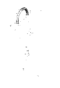
[0010] FIG. I is a perspective view of an illustrative kitchen faucet of
the present
disclosure mounted on a sink deck and fluidly coupled to hot and cold water
supplies;
[0011] FIG. 2 is a perspective view of the kitchen faucet of FIG. 1,
showing the spout
nest coupled to the docking cradle, and the pulldown sprayhead removed from
the spout nest;
[0012] FIG. 3 is a perspective view of the kitchen faucet of FIG. 1,
showing the spout
nest removed from the docking cradle, the pulldown sprayhead coupled to the
spout nest, and the
docking cradle rotated about the spout base;
[0013] FIG. 4 is a perspective view of the kitchen faucet of FIG. 1,
showing the spout
nest removed from the docking cradle, the pulldown sprayhead removed from the
spout nest, and
the docking cradle rotated about the spout base;
[0014] FIG. 5 is an exploded perspective view of the kitchen faucet of FIG.
1;
[0015] FIG. 6 is a cross-sectional view taken along line 6-6 of FIG. 2;
[0016] FIG. 7 is a cross-sectional view taken along line 7-7 of FIG. 1;
[0017] FIG. 7A is a detailed view of FIG. 7;
[0018] FIG. 8 is a cross-sectional view of the illustrative spout base of
FIG. 7;
[0019] FIG. 9 is a partial exploded perspective view of the illustrative
spout base of FIG.
7;
[0020] FIG. 10 is a first exploded perspective view of the illustrative
spout nest of the
faucet of FIG. 1;
[0021] FIG. 11 is a second exploded perspective view of the illustrative
spout nest of
FIG. 1;
[0022] FIG. 12 is a perspective view of a spring spout hose guide according
to a further
illustrative embodiment of the present disclosure;
3
CA 02918026 2016-01-18
[0023] FIG. 13 is a partial cross-sectional view of the illustrative spout
base showing the
spring spout hose guide of FIG. 12;
[0024] FIG. 14 is an exploded perspective view of a further illustrative
kitchen faucet of
the present disclosure;
[0025] FIG. 15 is a perspective view of an upper retaining sleeve and wire
contact;
[0026] FIG. 16 is an exploded perspective view of the upper retaining
sleeve and contact
of FIG. 15;
[0027] FIG. 17 is a longitudinal cross-sectional view along the spout upper
tube of the
kitchen faucet of FIG. 14, showing the lower pivot coupling, the lower
capacitive coupling, the
upper pivot coupling, and the upper capacitive coupling;
[0028] FIG. 18 is a longitudinal cross-sectional view similar to FIG. 17,
showing an
alternative embodiment lower capacitive coupling;
[0029] FIG. 19 is a perspective view of an alternative embodiment upper
retaining sleeve
and spring contact;
[0030] FIG. 20 is an exploded perspective view of the upper retaining
sleeve and spring
contact of FIG. 19; and
[0031] FIG. 21 is a longitudinal cross-sectional view of the upper
retaining sleeve and
spring contact of FIG. 19.
DETAILED DESCRIPTION OF THE DRAWINGS
[0032] The embodiments of the invention described herein are not intended
to be
exhaustive or to limit the invention to precise forms disclosed. Rather, the
embodiments selected
for description have been chosen to enable one skilled in the art to practice
the invention.
[0033] Referring initially to FIGS. 1-4, an illustrative kitchen faucet 10
is shown
mounted to a deck 12 of a sink basin 14 and fluidly coupled to hot water and
cold water supplies,
illustratively conventional hot and cold water stops 16 and 18, through
flexible hot and cold
water risers or supply tubes 20 and 22, respectively. More particularly, the
kitchen faucet 10
illustratively includes a spout base 24 mounted to the sink deck 12.
4
CA 02918026 2016-01-18
[0034] With reference to FIGS. 1 and 5, the spout base 24 illustratively
includes a lower
hub 26 and a spout upper tube 28. The spout base 24 defines a passageway 30
extending along a
longitudinal axis 31 and receiving a flexible outlet tube 32. The tubes 20, 22
and 32 may be
formed of a conventional material, such as a polymer (illustratively a cross-
linked polyethylene
(PEX)).
[0035] With reference to FIG. 5, a mounting shank 34 illustratively extends
downwardly
from the lower hub 26 to below the sink deck 12. A mounting nut 36 threadably
couples with
the mounting shank 34 to clamp the spout base 24 to the sink deck 12. The
tubes 20, 22 and 32
may pass from below the sink deck 12, through the mounting shank 34 and into
the passageway
30 of the spout base 24.
[0036] A manual valve 38 may be supported within the spout base 24 and
includes hot
and cold water ports (not shown) fluidly coupled to the hot and cold water
supply tubes 20 and
22, and a mixed water outlet port (not shown) fluidly coupled to the outlet
tube 32. As is known,
the manual valve 38 may be a conventional mixing valve including a handle 40
coupled to a
valve stem 42 for controlling the flow rate and the temperature of water
delivered to the outlet
tube 32 from the supply tubes 20 and 22. Illustratively, the outlet tube 32 is
fluidly coupled to a
pullout sprayhead 44. More particularly, the outlet tube 32 extends downwardly
from the
manual valve 38 below the sink deck .12 and then loops back upwardly through
the spout base 24
to the sprayhead 44.
[0037] The pullout sprayhead 44 is removably coupled to a spout nest 46
which is
secured to a delivery spout 48 supported by the spout base 24. In turn, the
spout nest 46 is
removably coupled to a docking cradle 50 supported by the spout base 24. With
reference to
FIGS. 5 and 7, the sprayhead 44 may be of conventional design as including an
outer shell 52
and an internal waterway 54. The internal waterway 54 is fluidly coupled to
the outlet tube 32
for supplying water to outlets defined by the sprayhead 44, illustratively a
plurality of
circumferentially spaced spray outlets 56 and a central stream outlet 58. A
toggle switch 60 may
be operably coupled to the internal waterway 54 for alternating flow between
the outlets 56 and
58 (FIG. 7).
[0038] With reference to FIGS. 5, 7 and 8, the delivery spout 48
illustratively comprises
a spring spout 62 is supported by the spout base 24. Illustratively, the
spring spout 62 includes
CA 02918026 2016-01-18
an inner spring 64 and an outer sleeve 66. The spring spout 62 extends between
opposing first
and second ends 68 and 70, respectively. The first end 68 of the spring spout
62 is coupled to the
spout base 24, and the second end 70 of the spring spout 62 is coupled to the
spout nest 46. As
further detailed herein, first ends 72 and 74 of the inner spring 64 and the
outer sleeve 66 are
coupled to the spout base 24. Second end 76 of the inner spring 64 is freely
supported within the
outer sleeve 66 for relative movement therebetween, while second end 78 of
outer sleeve 66 is
coupled to the spout nest 46.
[0039] The inner spring 64 is illustratively a tension spring including a
plurality of metal
helical coils 82 surrounding the outlet tube 32. The inner spring 64 defines
an arc when in a
relaxed state. In operation, the inner spring 64 supports the outlet tube 32
and the spout nest 46
(and the sprayhead 44 when coupled thereto). Moreover, the inner spring 64 is
configured to
facilitate return of the spout nest 46 to its rest position within the docking
cradle 50 (FIG. I). In
this docked position, the spring spout 62 defines an arc within a vertical
plane extending through
the spout base 24 and the sprayhead 44.
[0040] The outer sleeve 66 is illustratively a tension spring including a
plurality of tightly
wound helical coils 84. The outer sleeve 66 defines is linear when in a
relaxed state. The outer
sleeve 66 protects the inner spring 64 and the outlet tube 32 from debris and
dirt, while providing
an aesthetically pleasing appearance. While the outer sleeve 66 is
illustratively formed from a
plurality of metal coils 84 (such as electro-polished stainless steel), the
sleeve 66 may be formed
of other materials, such as a flexible casing or tube formed of a polymer
(such as a plated
polymer).
[0041] The outlet tube 32 is supported for sliding movement within the
spout base 24 and
the spring spout 62. More particularly, the outlet tube 32 slides within the
spout base 24 and the
spring spout 62 as the sprayhead 44 is moved relative to the spout nest 46. In
other words, the
outlet tube 32 slides within the spout base 24 and the spring spout 62 as the
sprayhead 44 is
undocked or uncoupled from the spout base 24 and moved (i.e., pulled or
retracted) relative
thereto (for example, between the positions in FIG. 1 and FIG. 2).
[0042] As shown in FIG. 1, an illustrative retractor or a hose weight 90 is
slidably
mounted on the outlet tube 32 and is configured to help retract the outlet
tube 32 back into the
rest position as shown in FIG. 1 after the sprayhead 44 has been removed from
the spout nest 46.
6
CA 02918026 2016-01-18
The hose weight 90 may be of conventional design, such as the hose weight
disclosed in US
Patent Application Publication No. 2009/0145492 to Thomas et al.
[0043] As further detailed herein, the sprayhead 44 is fluidly coupled to
the outlet tube
32, and is releasably coupled or secured to the spout nest 46. The docking
cradle 50 is supported
by the spout base 24 and releasably couples to the spout nest 46.
[0044] With reference to FIGS. 5 and 7-9, the first end 68 of the spring
spout 62 is
secured to the spout base 24 through a spout base coupling 92. The spout base
coupling 92
illustratively includes a spring spout connector, illustratively a downwardly
extending connector
tube 94, rotatably secured within the spout upper tube 28 by a retainer such
as a retaining sleeve
96. A spring glide bushing 98 cooperates with a spring spout hub nut 100 and
to secure the first
end 68 of the spring spout 62 to the upper tube 28 of the spout base 24.
[0045] The spring spout hub nut 100 is threadably coupled to the spring
spout connector
94. As the spring spout hub nut 100 is threaded onto the spring spout
connector 94, tapered
walls 102 of the bushing 98 secure outwardly flared end coils 106 and 108 of
the inner spring 64
and the outer sleeve 66, respectively, of the spring spout 62. The bushing 98
includes a pair of
diametrically opposed flexible tabs 110 received within an annular groove 112
formed within the
spring spout hub nut 100, thereby axially securing the bushing 98 with the
spring spout hub nut
100. A spring spout washer 114 is secured to the first end 72 of the inner
spring 64 and prevents
metal to metal contact between the inner spring 64 and the spring spout
connector 94.
[0046] With reference to FIGS. 5-7A, 10 and 11, the spout nest 46
illustratively includes
a main body 120, a cover 122 and a sprayhead retainer 124. The main body 120
illustratively
includes a cylindrical base 126 and an upper connector 128. The base 126
includes a pair of
diametrically opposed tabs 130 configured to be received within slots 132
formed in the docking
cradle 50. The upper connector 128 includes a plurality of concentric ribs 134
that retain the
coils 84 at the second end 78 of the outer sleeve 66.
[0047] The cover 122 illustratively includes an upper annular lip 136 and a
downwardly
extending arcuate outer wall 138. The upper connector 128 of the main body 120
is received
within the upper annular lip 136. Illustratively, the main body 120 and the
cover 122 are formed
of polymers secured together through conventional means, such as adhesives,
ultrasonic welding,
heat staking, etc. For example, the main body 120 may be formed of an acetal
copolymer (e.g.,
7
CA 02918026 2016-01-18
Celcort M90), and the cover 122 may be formed of a plated acrylonitrile
butadiene styrene
(ABS). In other illustrative embodiments, the main body 120 and the cover 122
may be formed
of a single component, such as a molded polymer or a machined brass including
a plated outer
surface.
[0048] The sprayhead retainer 124 illustratively defines a magnetic
coupling 140 to
releasably couple the sprayhead 44 to the spring spout 62 through the spout
nest 46. While a
magnetic coupling 140 is shown in the illustrative embodiment, other
conventional couplings
may be substituted therefor, including spring fingers and bayonet couplings.
[0049] In the illustrative embodiment, the sprayhead retainer 124 includes
an outer
holder 142 and an inner base 144 that secure a magnet 146 and a backing plate
148. The magnet
146 may be a permanent magnet, illustratively formed of a ferromagnetic
material, such as iron,
nickel, cobalt, or alloys of rare earth metals. In certain illustrative
embodiments, the magnet 146
may be formed of neodymium. The backing plate 148 is configured to direct
magnetic fields
from the magnet 146 and thereby increase the attractive force of a magnetic
coupling 140. A tab
or clip 150 is illustratively received within an opening 151 to secure the
sprayhead retainer 124
to the main body 120. A magnetically attractive element 152 (e.g., a metal
washer) is supported
by the sprayhead 44. The magnet 146 and the magnetically attractive element
152 may be
coated, plated or overmolded (e.g., by a polymer) for protection from
moisture. Illustratively,
the magnetic coupling 140, including the sprayhead retainer 124 and the
magnetically attractive
element 152, may be similar to that disclosed in US Patent No. 8,496,028 to
Nelson et al.
[0050] Illustratively, the docking cradle 50 is rotatably coupled to the
spout base 24 by a
horizontal swing arm 154. More particularly, a collar 156 is threadably
coupled to the spring
spout connector 94. The spring spout connector 94 is rotatably supported
within the retainer
received within the spout upper tube 28.
[0051] The docking cradle 50 illustratively includes a c-shaped retainer
158 including
opposing arms 160a and 160b. Each arm 160a, 160b includes a vertical slot 132
configured to
receive tabs 130 of the spout nest 46. When the spout nest 46 is coupled to
the retainer 158, the
arcuate outer wall 138 of the cover 122 is received within an opening 162
defined between ends
of the opposing arms 160a, 160b, and the annular lip 136 of the cover 122
rests on an upper edge
164 of the retainer 158. Engagement between the tabs 130 and slots 132
rotationally orient and
8
CA 02918026 2016-01-18
secure the spout nest 46 relative to the retainer 158. In certain illustrative
embodiments, other
couplings, such as frictional interference, magnetic couplings, and/or spring
tabs may be used to
further secure the spout nest 46 to the docking cradle 50.
[0052] With reference now to FIGS. 12 and 13, in a further illustrative
embodiment, the
inner spring 64 may be replaced with a spring spout hose guide 170. The spring
spout hose
guide 170 illustratively includes a base 172 supporting an upwardly extending
guide portion 174.
The base 172 includes a cylindrical wall 176 defining a central opening 178 to
receive the outlet
tube 32. The guide portion 174 includes an arcuate wall 180 defining a groove
182 for receiving
the outlet tube 32. The arcuate wall 180 is curved in perpendicular axes. The
hose guide 170 is
illustratively formed of a flexible polymer, such as a polypropylene.
[0053] As shown in FIG. 13, the base 172 of the hose guide 170 is coupled
to the spout
base 24. The outer sleeve 66 is illustratively received over the guide portion
174 of the hose
guide 170. More particularly, the spout base coupling 92 illustratively
couples the hose guide
170 and the outer sleeve 66 to the spout base 24 through the spring spout
connector 94.
[0054] The illustrative kitchen faucet 10 has a plurality of different
modes of operation.
In an illustrative first mode of operation as shown in FIG. 1, the spout nest
46 is initially coupled
to the docking cradle 50, and the sprayhead 44 is coupled to the spout nest
46. In an illustrative
second mode of operation as shown in FIG. 2, the spout nest 46 is coupled to
the docking cradle
50, and the sprayhead 44 is removed from the spout nest 46. In this mode of
operation, the
kitchen faucet 10 operates as a conventional pulldown faucet.
[0055] In an illustrative third mode of operation as shown in FIG. 3, the
spout nest 46 is
removed from the docking cradle 50, and the sprayhead 44 is coupled to the
spout nest 46. In
this mode of operation, the kitchen faucet 10 may be operated as a
conventional spring spout. In
an illustrative fourth mode of operation as shown in FIG. 4, the spout nest 46
is removed from
the docking cradle 50, and the sprayhead 44 is removed from the spout nest 46.
[0056] With reference now to FIG. 14, a further illustrative kitchen faucet
210 is shown
as including many of the same features of kitchen faucet 10. As such, in the
following
description similar components will be identified with like reference numbers.
9
CA 02918026 2016-01-18
[0057] The illustrative kitchen faucet 210 illustratively includes a
capacitive sensor 212
operably coupled to the upper delivery spout 48 by a first or upper capacitive
coupling 214 and a
second or lower capacitive coupling 216. The capacitive sensor 212 is
illustratively operably
coupled to a controller 218. An actuator driven valve 220 is in electrical
communication with
the controller 218 and controls fluid flow from the manual valve 38 through
the outlet tube 32.
More particularly, a user's hand in contact with and/or in proximity to the
faucet 210 is
illustratively detected by the capacitive sensor 212 and causes the controller
218 to open the
actuator driven valve 220. Illustratively, the actuator driven valve 220 is an
electrically operable
valve, such as a solenoid valve.
[0058] Because the actuator driven valve 220 is controlled electronically
by controller
218, flow of water can be controlled using an output from the capacitive
sensor 212. As shown in
FIG. 14, when the actuator driven valve 220 is open, the faucet 210 may be
operated in a
conventional manner, i.e., in a manual control mode through operation of the
handle 40 of the
manual valve 38. Conversely, when the manual valve 38 is set to select a water
temperature and
flow rate, the actuator driven valve 220 can be touch controlled using the
capacitive sensor 212
as a touch sensor, or activated by using the capacitive sensor 212 as a
proximity sensor when an
object (such as a user's hands) are within a detection zone or area to toggle
water flow on and off.
[0059] More particularly, the output signal from the capacitive sensor 212
may be used to
control actuator driven valve 220 which thereby controls flow of water to the
outlet tube 32 from
the hot and cold water sources 16 and 18. By sensing capacitance changes with
capacitive sensor
212, the controller 218 can make logical decisions to control different modes
of operation of
faucet 210 such as changing between a manual mode of operation and a hands
free mode of
operation. Additional details regarding capacitive sensing systems and methods
for operating
faucets may be found, for example, in U.S. Patent No. 8,561,626 to Sawaski et
al., U.S. Patent
No. 7,690,395 to Jonte et al., U.S. Patent No. 7,150,293 to Jonte; and U.S.
Patent No. 8,613,419
to Rodenbeck et al.
[0060] Kitchen faucet 210 illustratively includes spout base 24 having
lower hub 26 and
spout upper tube 28. A first or upper pivot coupling 224 is defined between
the upper delivery
spout 48 and the spout upper tube 28, while a second or lower pivot coupling
226 is defined
between the lower hub 26 and the spout upper tube 28.
CA 02918026 2016-01-18
[0061] With reference to FIGS. 14-18, the upper pivot coupling 224
illustratively
includes a downwardly extending connector tube 228 rotatably supported within
an upper end of
the spout upper tube 28 by retaining sleeve 96. Retaining sleeve 96 is
illustratively fixed within
the spout upper tube 28 while rotatably receiving the downwardly extending
connector tube 228.
[0062] More particularly, the retaining sleeve 96 includes a distal
cylindrical side wall
230 and a plurality of proximal arms 232. The side wall 230 illustratively
includes a plurality of
circumferentially spaced, radially outwardly extending ribs 234 configured to
frictionally engage
with an inner surface 236 of the spout upper tube 28, thereby securing the
retaining sleeve 96 to
the spout upper tube 28. A tab 238 may be biased radially outwardly to engage
a recess or
opening 240 formed within a side wall 241 of the spout upper tube 28 to
further secure the
retaining sleeve 96 therewithin. The proximal arms 232 are illustratively
biased radially
inwardly to engage an outer surface 242 of the connector tube 228. The
retaining sleeve 96 is
illustratively formed of a polymer, such as an acetal copolymer (e.g., Celcon*
M90).
[0063] Spring spout hub nut 100 is illustratively threaded onto an annular
ring 244 of the
downwardly extending connector tube 228 to secure the first end 68 of the
spring spout 62 for
rotation relative to the spout upper tube 28. More particularly, the first end
68 of the spring
spout 62 is secured to the connector tube 228 for rotation therewith relative
to the spout upper
tube 28.
[0064] The lower hub 26 illustratively includes a base 246 and an upwardly
extending
connector tube 248 fixed to the base 246. The lower pivot coupling 226
illustratively includes
the upwardly extending connector tube 248 rotatably supported within a lower
end of the spout
upper tube 28 by a retaining sleeve 250. Retaining sleeve 250 is substantially
identical to the
retaining sleeve 96 as detailed above. Retaining sleeve 250 is illustratively
fixed within the
spout upper tube 28 while rotatably receiving the upwardly extending connector
tube 248.
[0065] More particularly, the retaining sleeve 250 includes a distal
cylindrical side wall
252 and a plurality of proximal arms 254. The side wall 252 illustratively
includes a plurality of
circumferentially spaced, radially outwardly extending ribs 256 configured to
frictionally engage
with an inner surface 236 of the spout upper tube 28, thereby securing the
retaining sleeve 250 to
the spout upper tube 28. A tab 258 may be biased radially outwardly to engage
a recess or
opening 260 formed within the side wall 241 of the spout upper tube 28 to
further secure the
retaining sleeve 250 thercwithin. The proximal arms 254 are illustratively
biased radially
11
CA 02918026 2016-01-18
inwardly to engage an outer surface 261 of the connector tube 248. The
retaining sleeve 250 is
illustratively formed of a polymer, such as an acetal copolymer (e.g., Celcon
M90).
[0066] With further reference now to FIGS. 15 and 16, the illustrative
upper capacitive
coupling 214 is shown as including a wire contact 262 having first and second
coils 264 and 266
wrapped around an outer surface 268 of the proximal arms 232 of the retaining
sleeve 96. The
wire contact 262 defines an inner protrusion or portion 270 and an outer
protrusion or portion
272. The wire contact 262 is illustratively formed of an electrically
conductive material, such as
a metal. The inner portion 270 is configured to contact the outer surface 242
of the downwardly
extending connector tube 228, while the outer portion 272 is configured to
contact the inner
surface 236 of the spout upper tube 28. An enhanced electrical connection, and
more
particularly an enhanced capacitive coupling 214 at the upper pivot coupling
224, is facilitated
by contact between the spout upper tube 28 and the downwardly extending
connector tube 228 as
provided by the wire contact 262.
[0067] With reference now to FIGS. 19-21, an alternative embodiment upper
capacitive
coupling 214' is shown as including a spring contact 274. More particularly,
an alternative
embodiment retaining sleeve 96' includes a cylindrical sidewall 230'
supporting opposing upper
and lower posts 276 and 278. The spring contact 274 extends axially between
upper and lower
ends 280 and 282. The upper end 280 of the spring contact 274 receives the
upper post 276, and
the lower end 282 of the spring contact 274 receives the lower post 278. The
spring contact 274
is illustratively formed of an electrically conductive material, such as a
metal.
[0068] An inner portion 284 of the spring contact 274 contacts the outer
surface 242 of
the downwardly extending connector tube 228, while an outer portion 286 of the
spring contact
274 contacts the inner surface 236 of the spout upper tube 28. The spring
contact 274 is
configured for an interference fit between the connector tube 228 and the
spout upper tube 28 to
maintain an electrical connection therebetween. As the connector tube 228 and
the spout upper
tube 28 rotate relative to each other about the upper pivot coupling 224, the
spring contact 274 is
configured to rotate about the upper and lower posts 276 and 278.
[0069] With further reference to FIGS. 14 and 17, the lower capacitive
coupling 216
illustratively includes a sleeve or bushing 290 retained on the upwardly
extending connector tube
248 by a keeper or retaining washer 292. The bushing 290 is illustratively
formed of an
electrically conductive material, such as a metal. The bushing 290 increases
the effective outer
12
surface area of the upwardly extending connector tube 248, and reduces the gap
294 between the
outer surface of the upwardly extending connector tube 248 and the inner
surface of the spout
upper tube 28, thereby providing for an enhanced electrical connection, and
more particularly for
an enhanced lower capacitive coupling 216.
[0070] With reference to FIG. 18, in an alternative embodiment of the
lower capacitive
coupling 216', a portion 296 of a sidewall 298 of the spout upper tube 28 may
be enlarged to
reduce the gap 294' between the outer surface 261 of the upwardly extending
connector tube 248
and the inner surface 236 of the spout upper tube 28. The reduced gap 294'
provides for an
enhanced electrical connection, and more particularly for an enhanced lower
capacitive coupling
216'.
[0071] Illustratively, the docking cradle 50' is supported for rotation
with the spout upper
tube 28 by horizontal swing arm 154. More particularly, collar 156 is
threadably coupled to a
cap 300 secured (e.g., brazed) to an upper end of the spout upper tube 28. .
The docking cradle 50
illustratively includes a c-shaped retainer 158' including opposing arms 160a
and 160b. The
retainer 158 is illustratively supported for rotation by a pivot coupling 302.
A magnet 304 may
be supported by the retainer 158' to provide a magnetic coupling with the
spout nest 46'. More
particularly, the spout nest 46' illustratively includes a magnetically
attractive material (e.g.,
metal) that is attracted to the magnet 304 to releasably couple the spout nest
46' to the retainer
158'. A wand retainer may be included to secure the magnet 304 to the spout
nest 146'.
[0072] The spout nest 46' illustratively includes upper and lower flanges
306 and 308
defining an annular groove 310 configured to receive the arms 160a and 160b of
the retainer
158'. A magnetic coupling similar to the magnetic coupling 140 as detailed
above is configured
to releasably couple the sprayhead 44 to the spring spout 62 through the spout
nest 46'.
[0073] Although the invention has been described in detailed with
reference to certain
preferred embodiments, variations of modifications exist within the scope of
the invention as
described and defined in the following claims.
13
CA 2918026 2019-01-09