Note: Descriptions are shown in the official language in which they were submitted.
CA 02918109 2016-01-12
WO 2015/003712 PCT/DK2014/050199
SYS _________________ FEM FOR MEASURING THE QUANTITY OF URINE
AND DEFECTING THE PRESENCE OF FAECES IN A NAPPY
The present invention relates to a system for measuring the quantity of urine
in an
absorbing material and, in some embodiments, detecting the presence of faeces,
for
example in a nappy, wherein one or more capacitive sensors are used to
determine the
state of fullness of liquid in the absorbing material and for detecting the
presence of
faeces.
Background of the invention
Alarms used in connection with measuring the presence of urine in nappies,
underwear
and sheets, etc. are known in the art in the form of various enuresis and
incontinence
products. Urine sensors in nappies are known in the prior art, but there are
none for
measuring faeces.
The conventional products are characterised by their emission of an alarm as
soon as
a liquid is present on the sensor, a so-called instant alarm. The products
typically
function by making a resistive measurement across a sensor in which no current
is
passing between the electrodes in a normal situation (when the nappy is dry).
In an
alarm situation, an electrical connection is created between the electrodes
via the liquid
between the electrodes, following which a given current will pass from one
electrode
to the other. The liquid, in these cases urine, works as a simple contact
between two
or more electrodes.
Examples of such systems are described in US 7,700,821 B2 and US 7,667,608 B2,
and the object of such systems is precisely to produce an alarm as quickly as
possible,
as urine on the sensor is an undesirable situation for children who are bed-
wetters or
for incontinence patients. The conventional resistive instant alarms are found
in
countless variants and are, as noted above, included in nappies, panty liners,
CA 02918109 2016-01-12
WO 2015/003712 PCT/DK2014/050199
2
underwear, sheets, underlays and beds etc., all being characterised by the
above
technology and function.
Systems also exist for detecting quantities of liquid in, for example,
nappies, which
systems are characterised in being embedded in the liquid-absorbing material
or in
measuring through the liquid-absorbing material in the nappy. Examples of such
systems are described in US 2008/0278337 Al and WO 2013/013197 Al, the object
of which systems is to signal a degree of wetness in the liquid-absorbing
material in a
nappy.
Criteria for when there is a need for changing the nappies of children and
persons
suffering from incontinence are usually determined through subjective
assessments by
the nearest relatives or caregivers based on the time elapsed since the last
change, or
by feeling the nappy's degree of fullness. These methods entail several
disadvantages.
Firstly, they result in considerable variation in the degree of utilisation of
the nappies
and, consequently, a number of nappies will be changed, in which unutilised
absorbency remains. Secondly, the nappy's maximum absorbency may be exceeded,
resulting in overflow in situations, in which the nappy wearer experiences
excessive
discharge of urine. Finally, the practice of subjective assessment of the
criteria for
when a change of nappy is required is time consuming and attention demanding
for
relatives and caregivers irrespective of the assessment method used.
The presence of faeces in the nappy is an undesirable condition as it may
cause damage
to the wearer's skin. Faeces are only detected through visual checking or if
the user
can say so him-/herself. This is inappropriate.
This practice also gives occasion for considerations of whether the high
frequency of
cystitis among nappy wearers is caused by a prolonged exposure to moist
surroundings. Said practice makes it difficult to collect and compare data,
which could
help to improve, or even prevent, different side effects of wearing a nappy.
CA 02918109 2016-01-12
WO 2015/003712 PCT/DK2014/050199
3
Brief description of the invention
It is an object of the present invention to provide a more advanced alarm
system, which
does not produce an either/or alarm, but uses a more differentiated measuring
method
with the possibility of self-selected alarm levels, which can be adapted to
the institution
or wearer. In this way, the system cannot only enhance the possibilities for
improving
the conditions for the nappy wearer, but also the working environment and the
possibilities of preventing inappropriate situations.
Such a system is provided in the present invention, which relates to system
for
measuring and recording a quantity of liquid in an absorbing material, such as
the
quantity of urine in a nappy, which system comprises a sensor comprising a
first pair
of electrodes for measuring the quantity of liquid, which first pair of
electrodes is
arranged to be placed around the absorbing material in, for example, a nappy,
and a
data logger, which is arranged to apply an alternating voltage across the
first pair of
electrodes and, concurrently herewith, to measure the capacitance between the
two
electrodes of the first pair of electrodes and to calculate, based on the
measured
capacitance, an estimate of the quantity of liquid in the absorbing material.
Such a system is advantageous because it is able to continuously measure and
pass on
information on the quantity of liquid in a given absorbing item, such as a
nappy.
Greater awareness of when the nappy needs changing can thus be obtained.
To ensure that the system is intact and that the capacitance measurements are
correct,
it will be advantageous, concurrently with the capacitance measurements, to
check the
so-called "dissipation factor", which is an expression of an undesirable
resistive
connection between the two electrodes between which the capacitance is
measured.
This can be done, for example, by measuring the ohmic resistance between the
two
electrodes.
CA 02918109 2016-01-12
WO 2015/003712 PCT/DK2014/050199
4
In an embodiment of the invention, the sensor further comprises a second pair
of
electrodes, and the data logger is further arranged to be able to apply an
alternating
voltage across the second pair of electrodes and, concurrently herewith, to
measure the
capacitance between the two electrodes of the second pair of electrodes and to
estimate, based on the measured capacitance, whether a substance, for example
faeces,
is present adjacent the two electrodes of the second pair of electrodes.
In an embodiment of the invention, the data logger further comprises a contact
surface,
which is arranged to be placed in electrical contact with a body of a person,
and the
data logger is further arranged to be able to apply an alternating voltage
between the
two electrodes of the second pair of electrodes on the one side and this
contact surface
one the other side and, concurrently herewith, measure the capacitance between
the
two electrodes of the second pair of electrodes on the one side and the
contact surface
on the other side and to estimate, based on the measured capacitance, whether
a
substance, for example faeces, is present between the two electrodes of the
second pair
of electrodes and the body.
In these embodiments, the invention can measure and pass on an alarm when
faeces
are present in the nappy, such that greater awareness can be obtained of when
the
nappy needs changing.
In an embodiment of the invention, a temperature-measuring instrument is
arranged in
connection with the contact surface of the data logger.
Such temperature-measuring instrument will, for example, be able to be used
for
checking that the surface is in fact in contact with the body as desired. It
will also be
able, in certain cases, to be used for measuring the person's body
temperature.
In an embodiment of the invention, the data logger is provided with a
gyroscope and/or
an accelerometer.
CA 02918109 2016-01-12
WO 2015/003712 PCT/DK2014/050199
The use of a gyroscope and/or an accelerometer makes it possible to determine
the
spatial orientation of the system (and of a person wearing the system), which
makes it
possible to adjust the measurement algorithm accordingly and obtain better
utilisation
of the filler capacity.
5
In an embodiment of the invention, the data logger is provided with a GPS
tracking
module for localising the data logger.
In an embodiment of the invention, the data logger is provided with a GSM
modem
for telecommunication with the data logger.
One segment to be helped by the invention is persons with impaired cognitive
functions including Alzheimer's disease/dementia. In cases, where the
consequence of
this disease is a combination of incontinence and confusion, an embodiment
with a
GPS tracking system in the data logger can be a major advantage. In these
cases, where
the user has a requirement for both nappy and tracking, both can be combined
in one
unit. A combination of data logging and a GPS tracking system can also take
advantage
of the fact that a GPS tracking module and a GSM module can be switched off
until
the user is outside the local wireless network to which the data logger is
normally
connected, thus saving electricity.
In an embodiment of the invention, the alternating voltage applied has an
amplitude of
between 0.5 Vac and 15 Vac, preferably between 0.5 Vac and 10 Vac, most
preferably
between 1 Vac and 6 Vac.
In an embodiment of the invention, the alternating voltage applied has a
frequency of
between 1 kHz and 100 kHz, preferably between 5 kHz and 25 kHz, most
preferably
between 8 kHz and 12 kHz.
CA 02918109 2016-01-12
WO 2015/003712 PCT/DK2014/050199
6
Amplitudes and frequencies within these intervals have proved to produce good
measurement results and, furthermore, they mean that persons using the
invention
neither register nor are affected by the alternating voltage applied.
In an embodiment of the invention, the alternating voltage is applied for
short periods
at predefined intervals of between 5 seconds and 10 minutes, preferably
between 5
seconds and 1 minute.
Application of the alternating voltage at said intervals has been found to
produce good
measurement results at the same time as electricity is saved.
In an embodiment of the invention, the data logger is further arranged to be
able to
transmit signals, which are representative of the calculated estimations of a
quantity of
liquid or of the presence of a substance, wirelessly to one or more external
monitoring
stations.
This allows for remote monitoring of the calculated estimations of the
quantity of
liquid and the presence of, for example, faeces. More specifically, this means
that the
invention can be arranged to emit a signal when a predefined optimal, uniform
and
objective criterion, for example for nappy changing, is met.
In an embodiment of the invention, the signals, which are representative of a
quantity
of liquid, represent an absolute quantity of liquid, such as for example 300
ml.
In an embodiment of the invention, the signals, which are representative of a
quantity
of liquid, represent a relative quantity of liquid, such as for example 20% of
the
absorbing material's total capacity.
Depending on the application of the invention, it may be most advantageous to
define
the system, such that either absolute or relative values are estimated and
form the basis
for determining whether a predefined criterion is met.
CA 02918109 2016-01-12
WO 2015/003712 PCT/DK2014/050199
7
In an embodiment of the invention, the sensor with the one or two pairs of
electrodes
is arranged to be placed so that it extends along two opposite surfaces of the
absorbing
material, such as the two surfaces of a nappy facing towards the wearer and
away from
the wearer, respectively.
The fact that the sensor only extends on the surfaces of the absorbing
material, for
example a nappy, means that the sensor can be retrofitted without changing the
original
design of the product/material onto which it is fitted. The invention can be
fitted on an
arbitrary liquid-absorbing product/material, including, for example, all types
of
nappies, sanitary towels, panty liners etc.
In an aspect of the invention, it provides a method for measuring and
recording the
quantity of liquid in an absorbing material, for example a filler in a nappy,
which
method comprises the steps of:
- applying an alternating voltage across the two electrodes of a first pair
electrode of electrodes in a sensor, which first pair of electrodes is
arranged to
be placed on the underside, i.e. on the surface facing towards the centre of
the
earth, of an absorbing material,
- simultaneously measuring of the capacitance between these two electrodes of
the first pair of electrodes in the sensor, and
- calculating, based on the capacitance measured, an estimate of the
quantity of
liquid in the absorbing material.
In an embodiment of the invention, the method further comprises the steps of:
- applying an alternating voltage across the two electrodes of a second
pair of
electrodes in the sensor, which second pair of electrodes is arranged to be
placed opposite an area, in which a substance, the presence of which is
desired
to be estimated, such as for example faeces, can be expected to occur,
- simultaneously measuring of the capacitance between these two electrodes of
the second pair of electrodes in the sensor, and
CA 02918109 2016-01-12
WO 2015/003712 PCT/DK2014/050199
8
- calculating, based on the capacitance measured, an estimate of the
presence of
a substance, for example faeces, adjacent the two electrodes of the second
pair
of electrodes.
In an embodiment of the invention, the method further comprises the steps of:
- applying an alternating voltage between the second pair of electrodes on
the
one side and a contact surface arranged to be in electrical contact with a
body
of a person on the other side,
- simultaneous measuring of the capacitance between the second pair of
electrodes on the one side and the contact surface on the other side, and
- calculating, based on the capacitance measured, an estimate of the
presence of
a substance, for example faeces, between the second pair of electrodes and the
body.
The figures
A few embodiments of the present invention are described in more detail below
with
references to the figures, of which
Fig. 1 illustrates schematically a sensor for retrofitted use according to
an
embodiment of the invention as seen from the outside,
Fig. 2 shows the sensor of Fig. 1 as seen from the rear,
Fig. 3 shows the sensor of Fig. 1, wherein a part of the outer layer is
removed
to make internal layers of the sensor partly visible,
Fig. 4 shows the sensor of Fig. 2, wherein a part of the rear side
layer is removed
to make internal layers of the sensor partly visible,
CA 02918109 2016-01-12
WO 2015/003712 PCT/DK2014/050199
9
Fig. 5 shows a cross-section of the sensor of Figs. 1 and 3 as
indicated by the
A-A line therein,
Fig. 6 shows a cross-section of the sensor of Fig. 1 as indicated by
the B-B line
therein,
Fig. 7 illustrates schematically a nappy as seen from the inside with
the sensor
of Figs. 1-6 fitted therein,
Fig. 8 shows a cross-section of the nappy and sensor of Fig. 7 along the C-
C
line indicated therein with an indication of electrical fields,
Fig. 9 shows a cross-section of the nappy and sensor of Fig. 7 along
the D-D
line indicated therein with an indication of electrical fields,
Fig. 10 illustrates schematically an associated data logger
(transmitter) as seen
from the front,
Fig. 11 shows the data logger (transmitter) of Fig. 10 as seen from the
side,
Fig. 12 shows the data logger (transmitter) of Fig. 10 as seen from the
rear, and
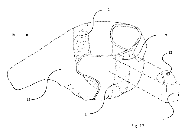
Fig. 13 illustrates schematically a perspective view of a complete
functioning
unit according to an embodiment of the invention with a nappy, a sensor
and a data logger.
The figures are reproduced as examples of how the present invention can be
implemented and should be regarded as non-limiting to the scope of protection
as laid
down in the claims.
CA 02918109 2016-01-12
WO 2015/003712 PCT/DK2014/050199
Detailed description of the invention
Fig. 1 shows an example of a complete sensor 1 according to an embodiment of
the
invention with a skin-friendly and moisture-proof electrically insulating
outer layer 2,
5 wherein the opening indicated through the outer layer 2 and a first non-
liquid
absorbing insulating layer (dielectric) 9 (not shown in Fig. 1) provides
electrical access
from the outside to a first electrode 7 for capacitive liquid detection. The
outer layer 2
can, for example, consist of a plastic film.
10 Fig. 2 shows the same sensor 1 from the rear side, which is covered by a
rear side layer
3, wherein an opening through the rear side layer 3 provides electrical access
to a
second and innermost electrode 4 for capacitive liquid sensing, and wherein
two other
openings through the rear side layer 3 and a second non-moisture absorbing
insulating
layer (dielectric) 5 (not shown in Fig. 2) provide electrical access to a
first 6 and a
second 8 electrode for capacitive faeces detection. The rear side layer 3 of
sensor 1 is
preferably an adhesive moisture-proof and electrically insulating layer, such
as for
example double-sided tape.
Fig. 3 shows the sensor 1 with the outer layer 2 shortened, thus exposing
parts of the
dielectrics 5, 9, the electrodes 6, 8 for capacitive faeces detection and the
rear side
layer 3. In fact, the outer layer 2 covers the entire sensor 1, but the inner
layers 5, 6, 8,
9 are shown in this way for explanatory reasons. The electrodes 6, 8 for
capacitive
faeces detection together constitute a capacitive sensor for detection of
faeces.
Fig. 4 shows the sensor 1 from the rear side, this time with the rear side
layer 3
shortened, thus exposing parts of second electrode 4 for capacitive liquid
detection and
of the second dielectric 5. In fact, the rear side layer 3 covers the entire
sensor 1, but
the inner layers 4-9 are shown in this way for explanatory reasons. The second
dielectric 5 has also been shortened. In fact, it covers the entire sensor 1
as indicated
in Fig. 3. The electrodes 4, 7 for capacitive liquid detection and the second
dielectric
5 together constitute a capacitive sensor for detection of the quantity of
liquid. The
CA 02918109 2016-01-12
WO 2015/003712 PCT/DK2014/050199
11
lengths of the electrodes 4, 7 for liquid detection correspond to the length
of the liquid
absorbing material for which measurements are desired. In Fig. 4, the
electrodes 6, 8
for capacitive faeces detection, the first dielectric 9 and the outer layer 2
are also
shown. The lengths of the electrodes 6, 8 for capacitive faeces detection are
adjusted
to fit the area in the nappy, in which faeces can be expected to occur.
Fig. 5 shows a cross-section of the sensor 1 as indicated by the A-A line in
Figs. 1 and
3. It illustrates schematically an example of a possible design of sensor 1
comprising
an outer layer 2 and a rear side layer 3 as described above. The dielectrics
5, 9 consist
of electrical insulating materials, such as for example foam tape,
polyethylene foam,
paper or an elastic liquid polymer applied in a printing process, which
polymer
subsequently solidifies. The four electrodes 4, 6, 7, 8 are made from
electrically
conductive materials, such as copper, aluminium, iron, graphite coating or a
conductive polymer, and can be installed as tapes with an adhesive or applied
in a
printing process directly on the carriers constituted by the dielectrics 5 and
9.
Fig. 6 shows a cross-section of the sensor 1 as indicated by the B-B line in
Fig. 1 with
the outer layer 2 and the rear side layer 3 as described above. The electrodes
6, 8 for
capacitive faeces detection as well as the second dielectric 5 are also shown
as
described previously.
Fig. 7 shows an arbitrary type of nappy seen from the inside. The surface
layer 15 of
the nappy is shown partly open for explanatory reasons to illustrate the
liquid
absorbing material 16 inside the nappy. In fact, the surface layer 15 covers
the entire
nappy. Sensor 1 is seen from the rear edge of the nappy across the area within
the
nappy, in which faeces can be expected to occur. Thus, the sensor is arranged
to
measure the presence of faeces.
Fig. 8 shows a cross-section of the nappy and sensor 1 as indicated by the C-C
line in
Fig. 7. When an alternating voltage is applied across the electrodes 4, 7 of
the
capacitive liquid sensor, an electrical field 17 is formed within the liquid
absorbing
CA 02918109 2016-01-12
WO 2015/003712 PCT/DK2014/050199
12
material 16. When an alternating voltage is applied across the electrodes 6, 8
of the
capacitive faeces sensor, an electrical field 18 is formed between the surface
of the
sensor and the body of a person wearing the nappy across the area of the
nappy, in
which faeces can be expected to occur.
Fig. 9 shows a cross-section of the nappy and sensor 1 as indicated by the D-D
line in
Fig. 7. The sensor 1 may be fastened to the surface of the nappy, using, for
example,
glue. The electrical field 18, which is formed when an alternating voltage is
applied
across the electrodes 6, 8 of the capacitive faeces sensor, is also seen.
Fig. 10 is a schematic front view of a data logger 10 according to an
embodiment of
the invention, wherein a housing 11 contains the electronics (measuring
circuit,
accelerometer, GPS, GSM modem, power supply and radio module, etc.) and a
battery,
a rubber hinge 12 is installed for fastening the housing 11 across the front
edge of the
nappy by means of, for example, a magnet contact, and a body sensor 13 creates
an
electrical connection to the body of a person wearing the nappy. The data
logger 10,
the nappy and the sensor 1 together constitute a complete functional liquid
and faeces
detection unit 19.
Fig. 11 shows the data logger 10 of Fig. 10 as seen from the side with the
housing 11,
the rubber hinge 12, the body sensor 13, and a plug 14 which creates
electrical
connections to the four electrodes 4, 6, 7, 8 of sensor 1.
Fig. 12 is a rear view of the same data logger 10, wherein the plug 14
functions as a
contact part for the four electrodes 4, 6, 7 and 8 of sensor 1. Thus, the plug
14 creates
the electrical connection to the four electrodes 4, 6, 7, 8 through the
openings designed
for this purpose at the top of sensor 1 as seen in Figs. 1 and 2, such that
the data logger
10 can easily be installed together with sensor 1.
Fig. 13 shows an arbitrary nappy, onto the outside of which is fitted a sensor
1, and
data logger 10, viewed in a perspective. The sensor 1 is centred in the
nappy's
CA 02918109 2016-01-12
WO 2015/003712 PCT/DK2014/050199
13
longitudinal direction. These three components together constitute a liquid
and faeces
detection unit 19 functioning separately in the complete system.
The unit 19 functions by the data logger 10 applying an alternating voltage
of, for
example, 2 Vac at a frequency of, for example, 10 kHz across the two
electrodes 4, 7
for capacitive liquid detection, concurrently measuring the capacitance
between the
electrodes 4, 7. Because the liquid sensor (consisting of the two electrodes
4, 7 and the
second dielectric 5) creates an electrical field 17 into the liquid absorbing
material 16
in the nappy, the capacitance measured will depend on the dielectric
properties of the
liquid absorbing material 16. This utilises the physical differences between a
dry and
a damp/wet liquid absorbing material 16. The dielectric constant for water
(and urine)
is approximately 80 times higher than the dielectric constant for air. The
effect on the
electrical field 17 of this difference in dielectric constants is utilised in
this design. The
relationship between the capacitance measured and the quantity of liquid in
the nappy
is approximately linear, always with a positive slope (the more liquid
present, the
higher the capacitance measured). Advantageously, the width of the second
electrode
4 can be approximately 50 % of the width of the first electrode 7 as indicated
roughly
in Fig. 5.
The electrodes 6, 8 for capacitive faeces detection detect the presence of
faeces in the
nappy. The sensor functions by the data logger 10 applying an alternating
voltage of,
for example, 2 Vac at a frequency of, for example, 10 kHz between the two
electrodes
6, 8 for capacitive faeces detection, concurrently measuring the capacitance
between
the electrodes 6, 8. These electrodes 6, 8 are electrically and capacitively
insulated
from the surroundings by means of the two dielectric layers 5, 9 as indicated
in Figs.
3-5. As indicated in Figs. 3 and 4, the first dielectric 9 is shorter than the
two electrodes
4, 7 and the second dielectric 5, which creates an opening to the electrodes
6, 8 at one
end thereof. This opening provides increased capacitive sensitivity in the
area, in
which faeces are expected to occur. Thus, the capacitive faeces sensor
consisting of
the two electrodes 6, 8 and the two dielectrics 5, 9 forms an electrical field
18 with
increased sensitivity in the area, in which the first dielectric 9 is not
present. The
CA 02918109 2016-01-12
WO 2015/003712 PCT/DK2014/050199
14
dielectric constant for faeces is many times higher than the dielectric
constant for air.
The effect on the electrical field 18 of this difference in dielectric
constants is utilised
in this design.
In a variant of the invention, the capacitive faeces sensor consists of the
two electrodes
6, 8 and the two dielectrics 5, 9 as described above in combination with a
body sensor
13. In this embodiment, the data logger 10 applies an alternating voltage of,
for
example, 2 Vac at a frequency of, for example, 10 kHz between the body sensor
13 on
the one side and the two electrodes 6, 8 on the other side, concurrently
measuring the
capacitance between the body sensor 13 on the one side and the electrodes 6, 8
on the
other side. The alternating voltage applied between the body sensor 13 and the
two
electrodes 6, 8 forms an electrical field between the body of a wearer of the
complete
unit 19 and the designed sensitive area with electrodes 6, 8, in which faeces
are
expected to occur. The electrical field and, consequently, the capacitance
measured
between the body and the electrodes 6, 8, is depend on the presence of faeces,
because
the dielectric constant for faeces is many times higher than the dielectric
constant for
air. The effect of this difference on the electrical field between the body
and the
electrodes 6, 8 is utilised in this design.
Increased reliability of diagnosing the presence of faeces in, for example, a
nappy is
obtained through a combination of measurements between the electrodes 6, 8 and
the
body via the body sensor 13.
Advantageously, the application of alternating voltages to the electrodes 4,
6, 7, 8 and
the corresponding measurements of capacitance can be done at predefined time
intervals of, for example, 10 seconds or 1 minute and temporally shifted in
relation to
each other in the sense that not more than one measurement is taken at any
given time.
The capacitances measured between the two electrodes 4, 7 for capacitive
liquid
detection are equated to estimates of the state of fullness of liquid, whereas
the
capacitances measured between the two electrodes 6, 8 for capacitive faeces
detection
CA 02918109 2016-01-12
WO 2015/003712 PCT/DK2014/050199
(and in some embodiments) the body of a wearer of a nappy, is equated to
estimates
of whether or not faeces are present in the nappy.
CA 02918109 2016-01-12
WO 2015/003712 PCT/DK2014/050199
16
List of reference numbers
1. Complete retrofitted sensor
2. Moisture-proof and electrically insulating outer layer of the sensor
3. Adhesive, moisture-proof and electrically insulating rear side layer of the
sensor
4. Second and innermost electrode for capacitive liquid detection
5. Second non-moisture absorbing insulating layer (dielectric)
6. First electrode for capacitive faeces detection
7. First electrode for capacitive liquid detection
8. Second electrode for capacitive faeces detection
9. First non-liquid absorbing insulating layer (dielectric)
10. Complete data logger (transmitter) for fitting on sensor and nappy
11. Housing for data logger containing printed circuit board, accelerometer,
GPS,
GSM modem radio and battery, etc.
12. Rubber hinge for fastening the data logger to the nappy and for the body
sensor
13. Body sensor for creating electrical connection to the wearer's body
14. Plug for electrical contact with the four electrodes in the sensor
15. Surface layer of an arbitrary standard nappy
16. Liquid-absorbing material within an arbitrary nappy
17. Electrical field from the capacitive liquid sensor
18. Electrical field from the capacitive faeces sensor
19. Assembled functional unit comprising nappy, sensor and data logger