Note: Descriptions are shown in the official language in which they were submitted.
CA 02919002 2016-01-21
WO 2015/013262
PCT/US2014/047592
EXPANDED BEAM FIBER OPTIC CONNECTOR, AND CABLE ASSEMBLY, AND
METHODS FOR MANUFACTURING
CROSS-REFERENCE TO RELATED APPLICATION(S)
This application is being filed on July 22, 2014, as a PCT International
Patent application and claims priority to U.S. Patent Application Serial No.
61/857,020
filed on July 22, 2013 and to U.S. Patent Application Serial No. 61/857,015
filed on July
22, 2013, the disclosures of which are incorporated herein by reference in
their entireties.
TECHNICAL FIELD
The present disclosure relates generally to optical fiber communication
systems. More particularly, the present disclosure relates to fiber optic
connectors, fiber
optic connector and cable assemblies and methods for manufacturing.
BACKGROUND
Fiber optic communication systems are becoming prevalent in part because
service providers want to deliver high bandwidth communication capabilities
(e.g., data
and voice) to customers. Fiber optic communication systems employ a network of
fiber
optic cables to transmit large volumes of data and voice signals over
relatively long
distances. Optical fiber connectors are an important part of most fiber optic
communication systems. Fiber optic connectors allow two optical fibers to be
quickly
optically connected and disconnected.
A typical fiber optic connector includes a ferrule assembly supported at a
front end of a connector housing. The ferrule assembly includes a ferrule and
a hub
mounted to a rear end of the ferrule. A spring is used to bias the ferrule
assembly in a
forward direction relative to the connector housing. The ferrule functions to
support an
end portion of at least one optical fiber (in the case of a multi-fiber
ferrule, the ends of
multiple fibers are supported). The ferrule has a front end face at which a
polished end of
the optical fiber is located. When two fiber optic connectors are
interconnected, the front
end faces of their respective ferrules abut one another and the ferrules are
forced together
by the spring loads of their respective springs. With the fiber optic
connectors connected,
their respective optical fibers are coaxially aligned such that the end faces
of the optical
fibers directly oppose one another. In this way, an optical signal can be
transmitted from
1
CA 02919002 2016-01-21
WO 2015/013262
PCT/US2014/047592
optical fiber to optical fiber through the aligned end faces of the optical
fibers. For many
fiber optic connector styles, alignment between two fiber optic connectors is
provided
through the use of a fiber optic adapter that receives the connectors, aligns
the ferrules and
mechanically holds the connectors in a connected orientation relative to one
another.
Connectors are typically installed on fiber optic cables in the factory
through a direct termination process. In a direct termination process, the
connector is
installed on the fiber optic cable by securing an end portion of an optical
fiber of the fiber
optic cable within a ferrule of the connector. After the end portion of the
optical fiber has
been secured within the ferrule, the end face of the ferrule and the end face
of the optical
fiber are polished and otherwise processed to provide an acceptable optical
interface at the
end of the optical fiber.
Connectors can also be installed on fiber optic cables using an optical
splice. The optical splice can be mechanical splice or a fusion splice.
Mechanical splices
are often used for field terminated connectors. Fusion splices can be used to
fusion splice
the optical fiber of the fiber optic cable to the rear end of an optical fiber
stub secured
within a ferrule. United States Patent Application Publication Pub. No. US
2014/0064665
Al discloses example splice-on connector configurations.
What is needed are methods and structures for reducing signal loss at
demateable interfaces of fiber optic connectors.
SUMMARY
Teachings of the present disclosure relate to methods and structures for
increasing the fiber mode field diameter at the demateable interface between
two fiber
optic connectors so as to reduce signal loss at the interface.
One aspect of the present disclosure relates to a fiber optic cable and
connector assembly. The assembly includes a ferrule having a front end and a
rear end, a
cable optical fiber, an optical fiber stub having a first and second portion
and a beam
expanding fiber segment optically coupled between the cable optical fiber and
the optical
fiber stub. The second portion of the optical fiber stub projects rearwardly
from the rear
end of the ferrule to be spliced. In one example, the optical fiber stub has a
constant mode
field diameter along its length and has a larger mode field diameter than the
cable optical
fiber.
2
CA 02919002 2016-01-21
WO 2015/013262
PCT/US2014/047592
Another aspect of the present disclosure relates to a fiber optic cable and
fiber assembly. The assembly includes a ferrule having a front end and a rear
end, an
expanded beam fiber segment having a front portion secured within the ferrule
and a rear
portion that projects rearwardly from the rear end of the ferrule, and a fiber
optic cable
having a single mode optical fiber optically coupled to the expanded beam
fiber segment
at a splice location behind the rear end of the ferrule.
A variety of additional aspects will be set forth in the description that
follows. The aspects relate to individual features and to combinations of
features. It is to
be understood that both the foregoing general description and the following
detailed
description are exemplary and explanatory only and are not restrictive of the
broad
inventive concepts upon which the embodiments disclosed herein are based.
BRIEF DESCRIPTION OF THE DRAWINGS
FIG. 1 is a longitudinal cross-sectional view of a fiber optic cable and
connector assembly in accordance with the principles of the present
disclosure;
FIG. 2 is an enlarged view showing a ferrule hub and splice locations for
the fiber optic cable and connector assembly of FIG. I;
FIG. 3 is a schematic, longitudinal cross-sectional view showing the mode
field for an optical fiber structure of the fiber optic cable and connector
assembly of FIG.
1;
FIG. 4 is a schematic longitudinal cross-sectional view showing the mode
field for an alternative optical fiber structure that can be used in the fiber
optic cable and
connector assembly of FIG. 1;
FIG. 5 is a cross-sectional view taken along section line 5-5 of FIG. 3;
FIG. 6 is a cross-sectional view taken along section line 6-6 of FIG. 3;
FIG. 7 is a cross-sectional view taken along section line 7-7 of FIG. 3;
FIG. 8 is a flow chart illustrating an example method in accordance with
the principles of the present disclosure for manufacturing the fiber optic
cable and
connector assembly of FIG. 1;
FIG. 9 is a longitudinal cross-sectional view of a fiber optic cable and
connector assembly in accordance with the principles of the present
disclosure;
3
CA 02919002 2016-01-21
WO 2015/013262
PCT/US2014/047592
FIG. 10 is a front, perspective, cross-sectional view of the fiber optic cable
and connector assembly of FIG. 9;
FIG. 11 is a perspective view of a ferrule assembly in accordance with the
principles of the present disclosure;
FIG. 12 is a perspective view of fibers shown in the ferrule assembly of
FIG. 11;
FIG. 13 cross-sectional view of an expanding beam fiber segment shown in
the ferrule assembly of FIG. 12;
FIG. 14 a cross-sectional view of a single mode optical fiber shown in the
ferrule assembly of FIG. 12;
FIG. 15 is a perspective view of a ferrule assembly with an odd integer %-
pitch GRIN lens in accordance with the principles of the present disclosure;
FIG. 16 is a perspective view of a ferrule assembly with an even integer %-
pitch GRIN lens in accordance with the principles of the present disclosure;
and
FIG. 17 is a flow chart illustrating a method for assembling a ferrule
assembly in accordance with the principles of the present disclosure.
DETAILED DESCRIPTION
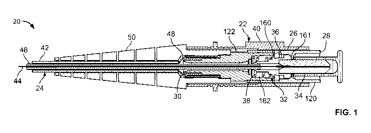
FIG. 1 illustrates a fiber optic cable and connector assembly 20 in
accordance with the principles of the present disclosure. The fiber optic
cable and
connector assembly 20 includes a fiber optic connector 22 secured to the end
of a fiber
optic cable 24. The fiber optic connector 22 includes a connector body 26
having a front
end 28 and a rear end 30. The fiber optic connector 22 also includes a ferrule
assembly 32
mounted within the connector body 26. Ferrule assembly 32 includes a ferrule
34 having
a rear end supported within a ferrule hub 36. A spring 38 biases the ferrule
assembly 32 in
a forward direction relative to the connector body 26. The fiber optic
connector 22 also
includes a release sleeve 40 that is mounted over the connector body 26 that
can be pulled-
back relative to the connector body to release the front end 28 of the
connector body 26
from a corresponding fiber optic adapter. The fiber optic cable 24 is shown
including an
outer jacket 42 that encloses a cable optical fiber 44 positioned within a
protective buffer
46 (e.g., a buffer layer such as a loose buffer layer, a tight buffer layer or
a loose/tight
buffer layer). The fiber optic cable 24 also includes a strength layer 48
(e.g., aramid yarn
or another type of tensile reinforcing material) positioned between the buffer
tube 46 and
the outer jacket 42. The strength layer 48 is shown anchored (e.g., crimped)
to the rear
4
CA 02919002 2016-01-21
WO 2015/013262
PCT/US2014/047592
end 30 of the connector body 26. The fiber optic connector 22 includes a
tapered boot 50
that provides strain relief and/or fiber bend radius protection at the
interface between the
fiber optic connector 22 and the fiber optic cable 24.
Referring to FIG. 2, the fiber optic connector 22 includes a fiber structure
52 that is optically coupled (e.g., spliced) to the cable optical fiber 44.
The fiber structure
52 includes an optical fiber stub 54 secured (e.g., adhesively affixed) within
a longitudinal
bore 56 of the ferrule 34. The optical fiber structure 52 also includes a beam
expanding
fiber segment 58 positioned between the cable optical fiber 44 and the optical
fiber stub
54. The beam expanding fiber segment 58 is configured for expanding light
beams
traveling in a direction from the cable optical fiber 44 toward the optical
fiber stub 54 and
for focusing light beams traveling in a direction from the optical fiber stub
54 toward the
cable optical fiber 44. The optical fiber stub 54 can include a construction
for maintaining
a constant mode field diameter along a length of the optical fiber stub 54. It
will be
appreciated that the phrase "constant mode field diameter along a length of
the optical
fiber stub" means that the mode field diameter is generally constant along the
length of the
optical fiber stub and includes embodiments where minor variations in diameter
that do
not have a meaningful impact on optical signals passing therethrough are
present.
As used herein, "mode field" means the portion of an optical fiber through
which light passes during a transmission through the optical fiber of a light
signal having a
predetermined wavelength. It will be appreciated that the "mode field" of a
given optical
fiber may vary depending upon the wavelength of the light signal being
transmitted
therethrough. As used herein, the "mode field area" is the transverse cross-
sectional area
of the mode field at a given location of the optical fiber. The "mode field
area" is
typically circular and defines a mode field diameter across the mode field
area. The mode
field diameter can be defined as where the power density is reduced to 1/e2 of
the
maximum power density. The mode field area can also be referred to as a "spot
area" or
"beam area" and the mode field diameter can also be referred to as the spot
size or beam
width.
It will be appreciated by those of skill in the art that the fiber optic
connector 22 depicted at FIG. 1 is an SC style connector. It will be
appreciated that the
various aspects of the present disclosure are also applicable to other types
of connectors
having different form factors. Example other types of connectors include LC
connectors,
ST connectors, or ruggedized/hardened connectors of the type disclosure at
U.S. Patent
Nos. 7,744,286 and 7,090,407 which are hereby incorporated by reference.
5
CA 02919002 2016-01-21
WO 2015/013262
PCT/US2014/047592
Referring again to FIG. 1, the ferrule 34 can be positioned at least partially
within the connector body 26 adjacent the front end 28 of the connector body
26. As
shown at FIG. 2, the ferrule 34 includes a front end 60 positioned opposite
from a rear end
62. The front end 60 includes an end face 64 at which an interface end 66 of
the optical
fiber stub 54 is located. The longitudinal bore 56 of the ferrule 34 extends
through the
ferrule 34 from the front end 60 to the rear end 62. The optical fiber stub 54
includes a
first portion 68 and a second portion 70. The first portion 68 can be secured
within the
longitudinal bore 56 of the ferrule 34 and the second portion 70 can extend
rearwardly
from the ferrule 34. The first portion 68 of the optical fiber stub 54 is
preferably secured
by an adhesive (e.g., epoxy) within the longitudinal bore 56 of the ferrule
34. The
interface end 66 of the optical fiber stub 54 can include a polished end face
accessible at
the front end 60 of the ferrule 34. The optical fiber stub 54 can extend all
of the way
through the ferrule 34 without any splices within the ferrule 34.
In one example, the optical fiber stub 54 has a construction designed and
configured to maintain a constant mode field diameter along its length. In one
example,
the optical fiber stub 54 is a step-index optical fiber having a core 200 (see
FIG. 3)
surrounded by a cladding 202 (see FIG. 3) with a discrete radial step in
refractive index
between the core and the cladding. In certain examples, the optical fiber stub
54 is
designed to inhibit the excitation of multiple transmission modes over a
predetermined
range of wavelengths (e.g., 1260-1650 nanometers). Thus, the stub 54 supports
only a
single fundamental mode over the predetermined range of wavelengths. In
certain
examples, the optical fiber stub 54 has a core diameter greater than 10
micrometers, or
greater than 12 micrometers, or greater than 20 micrometers, or greater than
30
micrometers, or greater than 40 micrometers, or greater than 50 micrometers.
In other
examples, the optical fiber stub 54 has a core diameter within the range of 50
to 100
micrometers. In other examples, the optical stub fiber 54 has a core diameter
in the range
of 10 to 125 micrometers. In still other examples, the optical fiber stub 54
can have a
cladding having an outer diameter in the range of 120 to 130 micrometers.
Referring to FIG. 2, the longitudinal bore 56 of the ferrule 34 can have a
stepped diameter. For example, the longitudinal bore 56 can have a first
diameter dl that
is larger than a second diameter d2. The first diameter di can be positioned
at the front
end of the ferrule 34 and the second diameter d2 can be positioned adjacent
the rear end of
the ferrule 34. In certain examples, the portion of the optical fiber stub 54
within the
section of the longitudinal bore 56 having the first diameter dl can be
protected by a
6
CA 02919002 2016-01-21
WO 2015/013262
PCT/US2014/047592
protective coating 55 (e.g., acrylate or other polymeric material) and the
portion of the
optical fiber stub 54 within the section of the longitudinal bore 56 having
the second
diameter d2 includes bare glass (i.e., a glass core and cladding that is not
surrounded by a
protective coating).
In certain examples, the cable optical fiber 44 is a step-index optical fiber
having a core 204 (see FIG. 3) surrounded by a cladding 206 (see FIG. 3). In a
step index
optical fiber, a discrete step in refractive index is provided radially
between the core and
the cladding. In one example, the cable optical fiber 44 functions as a single
mode optical
fiber and supports a single fundamental transmission mode for light
transmissions having
wavelengths in the predetermined wavelength range (e.g., 1260-1650 nanometers)
specified with respect to the optical fiber stub 54. In certain examples, the
cable optical
fiber 44 has a core diameter in the range of 5 to 15 micrometers, or in the
range of 8 to 12
micrometers, or of about 10 micrometers. In certain examples, the cable
optical fiber 44
can be configured to accommodate multi-mode optical transmissions. Portions of
the cable
optical fiber 44 can be protected by a coating 57 (e.g., acrylate or other
polymeric
material) that surrounds the cladding layer.
It is preferred for the core diameter of the optical fiber stub 54 to be
larger
than the core diameter of the cable optical fiber 44 (e.g., at least 50%
larger). In certain
examples, the core diameter of the optical fiber stub 54 is at least two
times, three times,
four times, five times, six times, seven times, eight times, nine times or ten
times as large
as the core diameter of the cable optical fiber 44. It is preferred for the
mode field
diameter of the optical fiber stub 54 to be larger than the mode field
diameter of the cable
optical fiber 44 (e.g., at least 50% larger). In certain examples, the mode
field diameter of
the optical fiber stub 54 is at least two times, three times, four times, five
times, six times,
seven times, eight times, nine times or ten times as large as the mode field
diameter of the
cable optical fiber 44.
As described above, in certain examples, the beam expanding fiber segment
58 of the optical fiber structure 52 can be configured to expand a light beam
traveling in a
first direction through the beam expanding fiber segment 58 and to focus a
light beam
traveling in an opposite second direction through the beam expanding fiber
segment 58.
In certain examples, the beam expanding fiber segment 58 can include a
collimator for
expanding /focusing light including, for example, a lens or an expanded core
of a fiber, in
particular, a thermally-expanded core. In certain examples, the beam expanding
fiber
segment 58 can include a lens such as a graded index (GRIN) lens. In a
preferred
7
CA 02919002 2016-01-21
WO 2015/013262
PCT/US2014/047592
example, the beam expanding fiber segment 58 can include a quarter pitch GRIN
lens. In
certain examples, the beam expanding fiber segment 58 can include a graded-
index optical
fiber having a core having a generally parabolic fiber refractive index
profile that has a
maximum value at the center of the core and that gradually decreases as the
core extends
radially away from the center of the core. It will be appreciated that the
beam expanding
fiber segment 58 functions to provide a gradual transition in mode field
diameter between
the cable optical fiber 44 and the optical fiber stub 54 (see FIG. 3 where the
mode fields
are the darkened portions of the fiber segments).
Referring to FIG. 3, an example mode field configuration for the optical
fiber structure 52 is depicted. As shown at FIG. 3, the beam expanding fiber
segment 58
is a GRIN lens that is spliced between the cable optical fiber 44 and the
optical fiber stub
54 so as to provide an optical coupling between the cable optical fiber 44 and
the optical
fiber stub 54. For example, the beam expanding fiber segment 58 is spliced to
the cable
optical fiber 44 at splice location 72 and the beam expanding fiber segment 58
is spliced to
the optical fiber stub 54 at splice location 74. In a preferred example, the
splice locations
72, 74 are positioned inside the ferrule hub 36 such that the ferrule hub 36
protects and
encloses the splice locations 72, 74. It will be appreciated that at the time
of splicing, the
beam expanding fiber segment 58 can include a bare glass section of graded
index fiber,
and the ends of the cable optical fiber 44 and the optical fiber stub 54 can
also be bare
glass (i.e., uncoated glass). After splicing, a protective buffer layer 76 can
be provided
over the splice locations 72, 74 and over the beam expanding fiber segment 58.
Thereafter, the ferrule hub 36 can be positioned (e.g., over molded) over the
rear end of
the ferrule 34 and over the optical fiber structure 52. In this way, the
second portion 70 of
the optical fiber stub 54, the beam expanding fiber segment 58, an end portion
of the cable
optical fiber 44 and the rear end of the ferrule 34 can all be contained
within the ferrule
hub 36. The spring 38 can abut against the ferrule hub 36 to bias the ferrule
assembly 32
in the forward direction.
Referring still to FIG. 3, the beam expanding fiber segment 58 provides a
gradual transition in mode field diameter from the smaller core of the cable
optical fiber
44 to the larger core of the optical fiber stub 54. FIG. 5 shows a mode field
area 208 of
the cable optical fiber 44 having a mode field diameter Dl. FIG. 7 shows a
larger mode
field area 210 of the optical fiber stub 54 having a mode field diameter 1)2.
FIG. 6 shows
a mode field area 212 provided by the beam expanding fiber segment 58 at a
location
8
CA 02919002 2016-01-21
WO 2015/013262
PCT/US2014/047592
about half way along the length of the beam expanding fiber segment 58. The
mode field
area 212 has a mode field diameter D3.
In the depicted example, splice location 74 is spaced rearwardly from the
rear end of the ferrule 34. In certain examples, the splice location 74 is
positioned no
more than 20 millimeters from the rear end of the ferrule 34. In still other
examples, the
splice location 74 is positioned 5 millimeters or less from the rear end of
the ferrule 34. In
some examples, the first and second splice locations 72, 74 are fusion
splices. The splice
locations 72, 74 can include factory fusion splice. A "factory fusion splice"
is a splice
performed at a manufacturing facility as part of a manufacturing process. In
certain
examples, an active alignment system is used to align the fiber sections prior
to splicing.
In still other examples, the splices can be a field splices.
FIG. 4 shows an alternative optical fiber structure 52a that can be used in
the fiber optic connector 22. The optical fiber structure 52a includes a two-
piece beam
expanding fiber segment 58a. The two-piece beam expanding fiber segment 58a
includes
a pre-expansion fiber 78 and a primary beam expanding fiber 80 joined at a
splice 82.
Similar to the previously subscribed example, the two-piece beam expanding
fiber
segment 58a is optically coupled between the cable optical fiber 44 and the
optical fiber
stub 54. The pre-expansion fiber 78 and the primary beam expanding fiber 80
cooperate
to expand light beams traveling from the cable optical fiber 44 to the optical
fiber stub 54
and to focus light beams traveling from the optical fiber stub 54 to the cable
optical fiber
44.
Referring back to FIG. 1, the connector body includes a front piece 120 and
a rear piece 122. The front piece 120 forms the front interface end 28 of the
fiber optic
connector 22 and the rear piece 122 is configured to allow the strength layer
48 (e.g.,
aramid yarn, fiberglass or other strength members capable of providing tensile
reinforcement to the fiber optic cable 24) of the fiber optic cable 24 to be
anchored. In
some examples, the strength layer 48 can be secured to the rear piece 122 of
the connector
body 26 with a mechanical retainer such as a crimped sleeve. In other
examples, adhesive
or other means can be used to secure the strength layer 48 to the connector
body 26.
The front and rear pieces 120, 122 of the connector body 26 can
interconnect the other by connection such as a snap fit connection, an
adhesive connection
or other type of connection. When the front and rear pieces 120, 122 are
connected
together, the spring 38 and the ferrule hub 38 are captured between the front
and rear
pieces 120, 122. The hub 36 can be shaped to include a flange 160 that engages
the spring
9
CA 02919002 2016-01-21
WO 2015/013262
PCT/US2014/047592
38. Additionally, the hub 36 can be configured to support the rear end of the
ferrule 34
within the connector body 26. Furthermore, a forward end of the flange 160 can
be
configured to engage a shoulder 161 within the connector body 26 to halt
forward
movement of the ferrule assembly 32 caused by the forward bias of the spring
38. The
spring 38 can be captured within a spring pocket 162 defined by the rear piece
122 and, as
described above, can function to bias the ferrule assembly 32 in a forward
direction
relative to the connector body 26. The hub 36 is a structure secured on the
ferrule 34 such
that the ferrule 34 and the hub 36 move together as a unit relative to the
connector body
26. As described above, the hub 36 can include structure that interferes with
an internal
structure (e.g., a stop) of the connector body 26 to limit the forward
movement of the
ferrule assembly 32 and to prevent the ferrule assembly 32 from being pushed
out the front
end of the connector body 26 by the spring 38.
As described above, the fiber optic connector 22 is shown having an SC-
type intermatability profile. As such, the fiber optic connector 22 can be
adapted to be
received within an SC-type fiber optic adapter that is used to couple two of
the connectors
together to provide an optical connection thereinbetween. When the fiber optic
connector
22 is inserted within a fiber optic adapter, exterior shoulders of the
connector body 26 are
engaged by latches of the fiber optic adapter to retain the fiber optic
connector 26 within
the fiber optic adapter. To release the fiber optic connector 22 from the
adapter, the
release sleeve 40 is slid rearwardly relative to the connector body 26 thereby
causing the
latches of the fiber optic adaptor to disengage from the exterior shoulders of
the connector
body 26 such that the fiber optic connector 22 can be withdrawn from the fiber
optic
adapter. An example fiber optic adaptor is disclosed at U.S. Patent No.
5,317,663 which is
hereby incorporated by reference in its entirety.
As described above, the beam expanding fiber segment 58 can include a
graded index lens (GRIN). A GRIN lens is made with a refractive index that
varies
parabolically as a function of the radius. The amount of expansion provided by
the GRIN
lens is dependent upon its construction and length. Typically, maximum
expansion is
achieved at multiples of the quarter pitch of the GRIN lens. As indicated
above, the
amount of expansion provided by the GRIN lens is dependent upon its
configuration and
length. By using the optical fiber stub 54 in combination with the beam
expanding fiber
segment 58, the beam expanding fiber segment 58 can be precisely controlled to
achieve a
desired level of expansion. The interface end 66 of the optical fiber stub 54
can be
polished in a conventional fashion to produce conventional end face geometry
such as, but
CA 02919002 2016-01-21
WO 2015/013262
PCT/US2014/047592
not limited to, straight, flat, curved or slanted configurations without
modifying the length
and degree of expansion provided by the beam expanding fiber segment 58. The
larger
mode field diameter provided through the cooperation of the beam expanding
fiber
segment 58 and the optical fiber stub 54 reduces the importance of precise co-
axial
alignment at the connector to connector interface. The ferrule 34 can be
constructed of a
relatively hard material capable of protecting and supporting the first
portion 68 of the
optical fiber stub 54. In one example, the ferrule 34 has a ceramic
construction. In other
examples, the ferrule 34 can be made of alternative material such as Ultem,
thermoplastic
material such as polyphenylene, sulfide (PPS), or other engineering plastics
or metals. In
certain examples, the ferrule 34 can have a longitudinal length in the range
of 5-15
millimeters.
In some examples, the hub 36 can have a polymeric construction that has
been overmolded over the rear end of the ferrule 34 and over the splice
locations (e.g.,
splice locations 72 and 74 or splice locations 72, 74 and 80). Additionally,
in certain
examples, the overmolded hub 36 can be formed of a hot melt adhesive or other
material
that can be applied and cured at relatively low molding temperatures and
pressures. The
ferrule hub 36 can also be formed from a UV curable material (i.e., materials
that cure
when exposed to ultraviolet radiation/light), for example, LTV curable
acrylates, such as
OPTOCASTrm 3761 manufactured by Electronic Materials, Inc. of Breckenridge,
Colorado; ULTRA LIGHT-WELD 3099 manufactured by Dymax Corporation of
Torrington, Connecticut; and 3M IM Scotch-Weld m manufactured by 3M of St.
Paul,
Minnesota. The use of UV curable materials is advantageous in that curing can
occur at
room temperature and at generally lower pressures (e.g., less than 30 kpsi,
and generally
between 20-30 kpsi). The availability of low pressure curing helps to insure
that the
components, such as the optical fibers, being overmolded are not damaged
during the
molding process. By protecting the splices within the hub at a location in
close proximity
to the ferrule 36, it is possible to manufacture a fiber optic connector that
is relatively short
in length. Providing one or more of the splice locations within 5 millimeters
of the rear
end of the ferrule 34 assists in designing the fiber optic connection in
compliance with
standard industry for customer side load and connector length specifications
(e.g., GR-326
size load and length requirements).
FIG. 8 is a flow chart illustrating an example method 150 for
manufacturing the fiber optic cable and connector assembly 20. In this
example, the
method 150 includes operations 152, 154, 156, 158, 160, 162, 164 and 166.
11
CA 02919002 2016-01-21
WO 2015/013262
PCT/US2014/047592
The operation 152 is performed to secure the optical fiber stub 54 in the
ferrule 74. As previously described, the optical fiber stub 54 can be
adhesively secured
within the bore of the ferrule 34.
The operation 154 is performed to polish the end face 64 of the ferrule 34
and the corresponding interface end 66 of the optical fiber stub 54 secured
within the
ferrule 34. The end face of the interface end 66 of the optical fiber stub 54
can be polished
having a desired geometry.
The operation 156 is performed to cleave the rear end of the optical fiber
stub 54. In one example, after cleaving, the rear end of the optical fiber
stub 54 can be
within 5 millimeters of the rear of the ferrule 34.
The operation 158 is performed to splice the beam expanding fiber segment
58 the rear end of the optical fiber stub 54. In another example, beam
expanding fiber
segment 58a can be spliced to the optical stub fiber instead of the beam
expanding fiber
segment 58.
The operation 160 is performed to cleave the beam expanding fiber
segment 58 to a controlled length. The length of the beam expanding fiber
segment 58 can
be controlled to achieve a desired amount of expansion. Both ends of the beam
expanding
fiber segment 58 can be cleaved prior to splicing to the optical fiber stub
54, or one end of
the beam expanding fiber segment 58 can be cleaved after splicing to the fiber
optic stub
54. In the case of the expanding fiber segment 58a, the pre-expansion fiber 78
and the
primary expansion fiber 80 can be cleaved to desired lengths, spliced together
and then the
primary expansion fiber 80 can be spliced to the optical fiber stub 54. Of
course, the order
of splicing can be varied such that the primary expansion fiber 80 is first
spliced to the
optical fiber stub 54 and then spliced to the pre-expansion fiber 78.
The operation 162 then is performed to splice the beam expanding fiber
segment 58 to the cable optical fiber 44. In another embodiment, the beam
expanding
fiber segment 58a is spliced to the cable optical fiber 44 by splicing the pre-
expansion
fiber 78 to the cable optical fiber 44.
The operation 164 is performed to install the ferrule hub 36 over the rear
end of the ferrule 34 and over the splice locations. The ferrule hub 36 can
contain and
protect the beam expanding fiber segment 58, 58a and the various splices used
to couple
the beam expanding fiber segment 58, 58a between the optical fiber stub 54 and
the cable
optical fiber 44.
12
CA 02919002 2016-01-21
WO 2015/013262
PCT/US2014/047592
The operation 166 is performed to install the ferrule assembly 32 in the
connector body 26. In certain embodiments, the rear connector piece 122 and
the spring
have been slid over the cable optical fiber 44 prior to over molding the hub.
In this step,
the ferrule assembly 32 is loaded into the front piece 120, the spring is slid
from the cable
optical fiber 44 to a position behind the hub and within the front connector
piece 120, and
the rear connector piece is slid forwardly from the cable optical fiber 44
into engagement
with the front connector piece 122 thereby capturing the hub and the spring
between the
front and rear connector pieces 120, 122.
Another aspect of the present disclosure relates to a method for mass
producing and distributing fiber optic connector assemblies. One aspect of the
method
relates to the centralized manufacturing of large quantities of ferrules
having optical fiber
stubs mounted therein. The optical fiber stubs can be of the type described
herein and can
include relatively large mode field diameters. In certain examples, the volume
of the
ferrule and stub combinations manufactured at a given centralized location can
exceed a
volume of 500,000; 1,000,000; 2,000,000; or 3,000,000 per year. The ferrule
and stub
combinations can be manufactured in a first factory location using highly
precise polishing
technology and equipment. The first factory location can be used to
manufacture the
ferrule and stub assemblies according to method operations 152-154 such that
the ferrule
assemblies manufactured at the central location each include a ferrule 34 and
an optical
fiber stub 54 of the type described herein having a constant mode field
diameter along its
length.
The method also leads to distributing the ferrule and stub assemblies
manufactured at the first factory location to regional factories/mass
production locations
closer to the intended point of sales. During shipping of the ferrule and stub
assemblies,
the rear portions 70 of the optical fiber stubs 54 can be coated with a
protective coating
layer (e.g., acrylate) to provide protection during transit, and or covered
with a protective
cap secured to the back end of the ferrule. Similarly, dust caps can be proved
over the
front ends of the ferrules 34. The ultimately small size of the ferrule and
stub fiber
assemblies allows large, large volumes of such ferrule and stub fiber
assemblies to be
effective shipped at relatively low cost. High costs associated with extensive
shipment of
cable can be significantly reduced. At the regional locations, the protective
coatings can
be stripped from the fiber stubs and operations 156-166 can be performed at
the regional
factory locations to splice the expansion fibers 58, 58a to the optical fiber
stubs 54 and to
splice the expansion fibers 58, 58a to the cable optical fibers 44.
13
CA 02919002 2016-01-21
WO 2015/013262
PCT/US2014/047592
In other embodiments, steps 152-160 can be performed at the central
manufacturing location. Once the optical fiber stubs 54 have been processed
with the
ferrules 34 and the beam expansion fiber 58, 58a have been spliced to the
optical fiber
stubs, protective caps (e.g., dust caps, can be placed over the front and rear
ends of the
ferrules to protect the interface ends 66 of the optical fiber stubs 54 as
well as the
expansion fibers 58 or 58a and their corresponding splices. Thereafter, the
protected
ferrule assemblies can be shipped to regional locations for final assembly on
a cable (e.g.,
steps 162-166).
FIGS. 9-10 show another example of a fiber optic cable and connector
assembly 300 in accordance with the principles of the present disclosure. The
fiber optic
cable and connector assembly 300 includes a fiber optic connector 302 secured
to the end
of a fiber optic cable 354. The fiber optic connector 302 includes a connector
body 304
having a front end 306 and a rear end 308. The fiber optic connector 302 also
includes a
ferrule assembly 420 mounted within the connector body 304. Ferrule assembly
420
includes a ferrule 422 having a rear end 428 supported within a ferrule hub
464. A spring
318 biases the ferrule assembly 420 in a forward direction relative to the
connector body
304. The fiber optic connector 302 also includes a release sleeve 328 that is
mounted over
the connector body 304 that can be pulled-back relative to the connector body
to release
the front end 306 of the connector body 304 from a corresponding fiber optic
adapter. The
fiber optic cable 354 is shown including an outer jacket 358 that encloses a
cable optical
fiber 356 positioned within a protective buffer 362 (e.g., a buffer layer such
as a loose
buffer layer, a tight buffer layer or a loose/tight buffer layer).
In this example, the cable optical fiber 356 functions as a single mode
optical fiber for light transmissions having wavelengths in the range 1310 to
1550
nanometers. In certain examples, the cable optical fiber 356 is a step-index
optical fiber.
In a step index optical fiber, a discrete step in refractive index is provided
radially between
the core and the cladding. The fiber optic cable 354 also includes a strength
layer 348
(e.g., aramid yarn or another type of tensile reinforcing material) positioned
between a
buffer tube 360 and the outer jacket 358. The strength layer 348 is shown
anchored (e.g.,
crimped) to the rear end 308 of the connector body 304. The fiber optic
connector 302
includes a tapered boot 310 that provides strain relief and/or fiber bend
radius protection at
the interface between the fiber optic connector 302 and the fiber optic cable
354.
Referring to FIGS. 11-12 an example mode field configuration for an
14
CA 02919002 2016-01-21
WO 2015/013262
PCT/US2014/047592
expanded beam fiber segment 424 is depicted. The expanded beam fiber segment
424 is a
GRIN lens that is spliced to optical fiber 446 at splice location 448 so as to
provide an
optical coupling between the optical fiber 446 and the expanded beam fiber
segment 424.
In one example, the splice location 448 can be behind the rear end 428 of the
ferrule 422.
In providing this construction, the mode field diameter of the optical fiber
446 can be
increased to any desired diameter. This arrangement has the advantage of
providing for
less sensitivity to lateral and longitudinal fiber core misalignment and less
sensitivity to
the contamination and defects of the fiber.
In certain examples, the splice location 448 can be positioned no more than
20
mm from the rear end 428 of the ferrule 422. In other examples, the splice
location 448
can be positioned 5 mm or less from the rear end 428 of the ferrule 422. In
some
examples, the splice location 448 is a fusion splice. The splice location 448
can be a
factory fusion splice. A "factory fusion splice" has been previously defined
above.
Accordingly, the description and features of such are also applicable in this
example.
The fiber optic connector 302 includes the expanded beam fiber segment
424 secured (e.g., adhesively affixed) within a longitudinal bore 334 of the
ferrule 422.
The expanded beam fiber segment 424 is configured for expanding light beams
traveling
in a direction from the cable optical fiber 356 toward the expanded beam fiber
segment
424 and for focusing light beams traveling in a direction from the expanded
beam fiber
segment 424 toward the cable optical fiber 356. The expanded beam fiber
segment 424
can include a construction for expanding a mode field diameter along a length
of the
expanded beam fiber segment 424.
The expanded beam fiber segment 424 can be referred to as a "GRIN lens."
The typical length of GRIN lens is about 300 micrometers depending on the
requirements.
This length typically corresponds to one quarter pitch. GRIN lens typically
has a length
tolerance of about 10 micrometers. An example expanded beam fiber is
disclosed at
UNITED States Patent No. 7,031,567, which is hereby incorporated by reference
in its
entirety. Maximum expansion achieved at the multiple of quarter pitch of GRIN
lens.
Referring again to FIG. 11, the ferrule 422 can include a front end 426
positioned opposite from a rear end 428. The front end 426 preferably includes
an end
face 430 at which an interface end 432 of the beam expanded fiber segment 424
is located.
The expanded beam fiber segment 424 includes a first portion 438 that can be
positioned
within the ferrule and extend therethrough from the front end 426 to the rear
end 428 of
CA 02919002 2016-01-21
WO 2015/013262
PCT/US2014/047592
the ferrule 422. The expanded beam fiber segment 424 can further include a
second
portion 440 that resides outside the ferrule 422. The first portion 438 can be
secured
within the ferrule 422 and the second portion 440 can extend reamardly from
the ferrule
422. The first portion 438 of the expanded beam fiber segment 424 can be
secured by an
adhesive (e.g., epoxy) within the ferrule bore 334 of the ferrule 422. The
interface end
432 preferably includes a polished end face 430 accessible at the interface
end 432 of the
ferrule 422. The expanded beam fiber segment 424 can extend all the way
through the
ferrule 422 without any splices within the ferrule 422.
Referring again to FIG. 9, the concepts and features of the connector body
304 and hub 464 are similar to the connector body 26 and hub 36 described
above in FIG.
1. As such, the description for the connector body 26 and hub 36 are hereby
incorporated
by reference in their entirety for the connector body 304 and hub 464. In
certain
embodiments, the hub 464 provides structure against which the bias of the
spring 318 can
be applied to bias the hub 464 and the ferrule 422 forwardly relative to the
connector body
304. The boot 310, the rear piece 314 and the spring 318 all can have internal
dimensions
(e.g., inner diameters) larger than an outer dimension (e.g., an outer
diameter) of the cable
354 such that during assembly/manufacturing the boot 310, the rear piece 314
and the
spring 318 can be slid back over the jacket 358 to provide space/clearance for
splicing and
application of the hub 464.
Referring to FIGS. 13-14, the expanded beam fiber segment 424 has a first
mode field diameter 1)4 and the expanded beam fiber segment 424 has a second
mode
field diameter D5. The expanded beam fiber segment 424 provides an expansion
of the
mode field diameter from the smaller mode field diameter D4 of the optical
fiber 446 to
the larger mode field diameter D5 of the expanded beam fiber segment 424. FIG.
13
shows a mode field area 366 of the expanded beam fiber segment 424 with the
first mode
field diameter D4. FIG. 14 shows a smaller mode field area 368 of the optical
fiber 446
with the second mode field diameter D5. In this example, the first mode field
diameter D4
can be at least two times as large as the second mode field diameter 1)5. In
other
examples, the first mode field diameter D4 can have a diameter expansion from
about 20
micrometers up to about 125 micrometers. The expanded beam fiber segment 424
can
convert the mode field of an optical signal of the optical fiber 446 to be
significantly
greater by expanding the second mode field diameter 135 up to a desired
expansion.
As shown in FIGS. 12 and 14, the optical fiber 446 can have a core
16
CA 02919002 2016-01-21
WO 2015/013262
PCT/US2014/047592
region 450 surrounded by a cladding region 352. In some examples, the core
region 450
of the optical fiber 446 can have a diameter in the range of about 8
micrometers to about
12 micrometers. In other examples, the cladding region 352 of the optical
fiber 446 can
have an outer diameter of about 125 micrometers. The optical fiber 446 can be
optically
coupled to the fiber optic cable 354.
It will be appreciated that the beam expanding fiber segment 358 functions
to provide an expansion in mode field diameter between the optical fiber 446
and the
expansion beam fiber segment 424 (see FIG. 12 where the mode fields are the
darkened
portions of the fiber segments).
Referring to FIG. 15, the expanded beam fiber segment 424 is depicted
within a ferrule 422. Due to the parabolic shape of the expanded beam fiber
segment 424,
the modal fields that can travel in the expanded beam fiber segment have
different
propagation coefficients, but are evenly distributed with respect to each
other. As such,
the constructive and destructive interference of the near-field is of periodic
nature. In this
example, the expanded beam fiber segment 424 has an odd integer 'A pitch
length Li. A 1/4
pitch length is about 3 micrometers. The "pitch" P of the lens is the fraction
of a full
sinusoidal period that the ray traverses in the lens (i.e., a lens with a
pitch of 0.25 has a
length equal to 1/4 of a sine wave, which would collimate a point source at
the surface of
the lens). The expanded beam fiber segment 424 is nicely collimated at the
interface end
432 of the ferrule 422 by exploiting the periodicity of the interfering modal
fields in the
expanded beam fiber segment 424. This provides for the desired selection of an
integer
multiple of the original expanded beam fiber segment 424 length. The expanded
beam
fiber segment 424 is a 1/4 pitch, so that the optical field is expanded. A 1/2
pitch (2 quarter
pitches) gives an intermediate focus F (see FIG. 16). Therefore, the odd
integer multiple
shown in FIG. 15 provides for the maximum expanded beam.
Referring to FIG. 16 the expanded beam fiber segment 424 is depicted
within the ferrule 422. In this example, the expanded beam fiber segment 424
has an even
integer 1/4 pitch length Li. The even integer multiple provides for an imaging
lens or
(focused) field. The even-integer multiple of the '4 pitch GRIN lens can be
constructed to
maintain polarization focus or expand. In some examples, the expanded beam
fiber
segment 424 can be larger than the ferrule 422 if the integer multiple is
large enough. The
expanded beam fiber segment 424 expand light beams traveling from optical
fiber 446 to
the expanded beam fiber segment 424 and to focus light beams traveling from
the
expanded beam fiber segment 424 to the optical fiber 446.
17
CA 02919002 2016-01-21
WO 2015/013262
PCT/US2014/047592
In some examples, the expanded beam fiber segment 424 can have at least
two pitch lengths. In other examples, the expanded beam fiber segment 424 can
have at
least 3 pitch lengths. In another example, the expanded beam fiber segment 424
can have
at least one pitch length and an even integer of quarter pitches. In another
example, the
expanded beam fiber segment 424 can have at least one pitch length and an odd
integer of
quarter pitches. Still in other examples, the expanded beam fiber segment 424
can have a
pitch length that is longer or shorter than a quarter pitch such that
expansion can be tuned
to achieve a desired mode field diameter. Therefore, the mode conversion can
be done by
giving more area around even number of pitches such that the pitch length can
be shorter
or longer. This can help to tune the expanded beam fiber segment 424 to a
mating fiber or
tune it in light of an air gap. This arrangement eliminates the need to have
an exact 'A
pitch. It is to be understood that the pitch length may vary with other
examples.
Turning again to FIG. 11, the loose buffbr tube 360 (i.e. furcation tube) can
surround and protect at least a portion of the optical fiber 356. The buffer
layer 362 can be
affixed or otherwise bonded to the exterior surface of the buffer tube 360 and
also can fill
a portion of the buffer tube 360 so as to bond with an interior surface of the
buffer tube
360. The buffer layer 362 projects rearwardly beyond a rearward end of a hub
464. In
this way, the rearward end of the hub 464 can circumferentially surround and
contact the
buffer layer 362 but does not contact the buffer tube 360. Thus, a mold for
forming the
hub 464 can be configured to shut-off around the buffer layer 362 rather than
the buffer
tube 360. In some examples, the buffer layer 362 has an outer diameter larger
than an
outer diameter of the buffer tube 360.
In the depicted example, the fiber optic connector 302 is shown as a
standard SC-type connector. The concepts and features of the fiber optic
connector 302
are similar to the fiber optic connector 22 described above. As such, the
description for
the fiber optic connector 22 is hereby incorporated by reference in its
entirety for the fiber
optic connector 302.
After the fusion splice has been completed, a protective layer 330 can be
placed, applied or otherwise provided over the optical fibers 446, 356 in the
region
between the rear end 428 of the ferrule 422 and a buffered/coated portion of
the optical
fiber 356. The fiber optic connector 302 fully complies with Telcordia GR-326
or similar
stringent industry or customer specifications.
The ferrule 422 can be constructed of a relatively hard material capable of
protecting and supporting the first portion 438 of the expanded beam fiber
segment 424.
18
CA 02919002 2016-01-21
WO 2015/013262
PCT/US2014/047592
The concepts and features of the ferrule 422 are similar to the ferrule 34
described above.
As such, the description for the ferrule 34 is hereby incorporated by
reference in its
entirety for the ferrule 422.
FIG. 17 is a flow chart illustrating an example method 500 for
manufacturing a ferrule assembly including the ferrule 422 and the expanded
beam fiber
segment 424 (i.e. GRIN lens). In this example, the method 500 includes
operations 502,
504, 506, 508, 510, and 512.
The operation 502 is performed to secure the expanded beam fiber segment
424 (i.e. GRIN lens) in the ferrule 422. An arbitrary length can be used to
glue the
expanded beam fiber segment 424 in the ferrule 422. An example of the expanded
beam
fiber segment 424 (i.e. GRIN lens) is shown and described with reference to
FIGS. 9-11.
The operation 504 is performed to polish an end of the ferrule 422 and an
end of the expanded beam fiber segment 424. The Examples of the ferrule 422
and the
expanded beam fiber segment 424 (i.e. GRIN lens) are shown and described in
FIG. 9.
The operation 506 is performed to cleave the expanded beam fiber segment
424 (i.e. GRIN lens) to a controlled pitch length. The selection can be made
to achieve a
specific amount of expansion.
The operation 508 is performed to splice the expanded beam fiber segment
424 (i.e. GRIN lens) to a single mode optical fiber 446. An example of the
single mode
optical fiber 446 is illustrated and described in more detail in FIGS. 9-10.
The operation 510 is performed to install the hub 464 over the ferrule 422.
An example of the hub 464 is illustrated and described in more detail in
FIG.9.
The operation 512 is performed to install the ferrule 422 in the connector
body 304. An example of the connector body 304 is illustrated and described in
more
detail in FIGS. 15-16.
Another aspect of the present disclosure relates to a method for mass
producing and distributing fiber optic connector assemblies. For example,
ferrule
assemblies can be manufactured in a first factoiy location using the highly
precise
polishing technology and equipment. The first factory location can be used to
manufacture the ferrule assembly according to method operations 502-506. By
manufacturing such large volumes of ferrule assemblies at one centralized
location, the
ferrule assemblies can be made efficiently and considerable capital investment
can be
made in premium quality manufacturing equipment and processes.
19
CA 02919002 2016-01-21
WO 2015/013262
PCT/US2014/047592
The method also relates to distributing ferrule assemblies manufactured at a
second location to regional factories/mass production locations closer to the
intended point
of sales. The relative small size of ferrule assemblies allows large volumes
of such ferrule
assemblies to be effectively shipped at relatively low costs. High costs
associated with
extensive shipment of cable can be significantly reduced. The method
operations 508-512
can be performed at regional factories/mass productions closer to the intended
point of
sales. A significant aspect of the method relates to a GRIN lens that can be
fusion spliced
to a single mode optical fiber at a location behind the rear end of the
fernile.
Aspects of the present disclosure allow ferrule assemblies to be
manufactured in large volumes at manufacturing locations where the process is
most class
effective. The ferrule assemblies, which are small in size, can be effectively
stripped in
bulk to factory/assembly locations closer to customer locations where the
ferrule
assemblies can be spliced to fiber optic cables and a final connector assembly
can take
place. In this way, shipping of the cable itself (which tends to be larger in
size and
weight) can be minimized. Also, final assembly can be made closer to customer
locations
thereby increasing lead times. Global supply chains can also be enhanced. From
the
foregoing detailed description, it will be evident that modifications and
variations can be
made without departing from the spirit and scope of the disclosure.
In other embodiments, aspects of the present disclosure can be used with
ferrule-less connectors where the optical fiber stub is not supported within a
ferrule.