Note: Descriptions are shown in the official language in which they were submitted.
CA 02919247 2016-01-28
LIFT ACTUATOR
TECHNICAL FIELD
[0001] The present
invention is directed to an improved lift actuator, and
more specifically to an electric lift actuator for use on a variety of lift
systems,
wherein the actuator includes various improvements that reduce cost and
improve the performance (e.g., increased overall maximum capacity) and
reliability of the actuator in addition to making the actuator, end-effector
and
components with common designs across several applications and/or load
ranges.
BACKGROUND ART
[0002] The use of
electric lift actuators is well-known in the materials handling
industry. Electric lifts are particularly useful, and have been applied in
several
embodiments to provide varying lift capabilities for personal lift devices for
lifting and
transporting loads. Examples of such devices include the Gorbel GForceTM and
Easy Arm TM systems.
[0003] More
specifically, the present invention is directed to a class of
material handling devices called balancers or lifts, which include a motorized
lift
pulley having a cable or line which, with one end fixed to the pulley, wraps
around the
pulley as the pulley is rotated, and an end-effector or operator control in
the form of a
pendant or similar electro-mechanical device that may be attached to the other
(free
or non-fixed) end of the cable. The end-effector has components that connect
to the
load being lifted, and the pulley's rotation winds or unwinds the line and
causes the
end-effector to lift or lower the load connected to it. In one mode of
operation, the
actuator applies torque to the pulley and generates an upward line force that
exactly
equals the gravity force of the object being lifted so that the tension in the
line
essentially balances the object's weight. Therefore, the only force the
operator must
impose to maneuver the object is the object's acceleration force.
[0004] In one class
of systems, these devices measure the human force or
motion and, based on this measurement, vary the speed or force applied by the
actuator (pneumatic drive or electric drive). An example of such a device is
U.S. Pat.
No. 4,917,360 to Yasuhiro Kojima, U.S. Pat. No. 6,622,990 to Kazerooni, and
U.S.
Pat. No. 6,386,513 to Kazerooni. U.S. Patent 6,622,990 for a "HUMAN POWER
AMPLIFIER FOR LIFTING LOAD WITH SLACK PREVENTION APPARATUS," to
- 1 -
CA 02919247 2016-01-28
Kazerooni., issued September 23, 2003. With this and with similar devices,
when the
human pushes upward on the end-effector the pulley turns and lifts the load;
and
when the human pushes downward on the end-effector, the pulley turns in the
opposite direction and lowers the load. Similar operation may be observed in
systems having what is frequently referred to as a "float mode" wherein an
operator's
application of upward or downward force to the load itself results in system-
assisted
movement of the load.
DISCLOSURE OF THE INVENTION
[0005] The embodiments disclosed herein are designed to provide several
improvements to existing electric actuator and lift systems. In a general
sense, the
improved design facilitates the standardization of the actuator design in
order to
reduce the number of components required to manufacture and service a broad
range of lift systems, whereby fewer components are changed between several
actuators having varying load-lifting ranges. The redesign also modifies
several
components in the actuator and the associated user controls (e.g., operator
control
pendant) so as to improve the reliability, serviceability and expandability of
the
controls.
[0006] Disclosed in embodiments herein is a lift actuator, comprising: a
controller; an electrical motor for driving the actuator, said motor operating
in
response to control signals from the controller, to rotate a drum upon which a
wire
rope, with one end fixed to the drum, is wound and unwound; and an operator
interface, attached near the free end of the wire rope, said operator
interface
including a detachable lifting tool, wherein the operator interface provides
signals
from the operator to the controller to control the operation of the actuator.
[0007] Also disclosed are: a frame for rotatably suspending the motor,
mechanical reduction and drum therefrom; a load sensor attached to the frame,
for
sensing the load as a result of rotation of the motor/reducer/drum assembly
when a
load is applied to the unwound end of the wire rope; a slack sensor for
sensing the
angle of orientation of the motor/ reducer/drum assembly and determining when
a
slack condition is present in response to a signal from the slack sensor,
mounted on
the rotating assembly in one embodiment; a universal motor and reducer
assembly
that may be fitted with one of a plurality of additional reducers in order to
alter the
capacity range of the actuator; a planetary reducer, wherein the mechanical
- 2 -
configuration of the reducer is substantially enclosed within the wire rope
pulley
drum; a cable guide for controlling the position and maintaining the wrap
integrity
(tightness) of the cable upon being wound upon or unwound from the drum;
adjustable cable limit sensors, triggered in response to the extreme axial
movement
of the cable guide as the cable is wound and unwound; and the cable guide
including
a plurality of threads for mating with grooves on the drum to provide the
lateral force
to move the guide as the cable is wound and unwound. Said grooves also serve
as
location for the wire rope on the drum, yielding precise, single layer
placement of the
wire rope on the drum.
[0008] Further disclosed relative to various alternative
embodiments of the
operator interface are: a handle; a pivotable coupling for attaching the
interface to the
wire rope, but permitting 360-degree rotation thereof relative to the rope by
way of a
pancake-like slip ring suitable for providing electrical contacts and an air
channel or
conduit therewith; a coil sensor for sensing a vertical component of a
displacement
applied to the handle, wherein the handle is coupled to a core passing within
the coil
by a flexible filament; a liquid crystal display on the interface to display
status
information to an operator; a non-contact, optical proximity sensor for
detecting the
presence of an operator's hand on the handle during operation; and a quick-
disconnect, bayonet-type or pin-type attachment for tools to be attached to
the
bottom of the interface.
[0009] Accordingly, in one aspect there is provided a lift system,
comprising:
a controller; an actuator, said actuator being responsive to said controller,
said
actuator including a pulley with a cable wound thereon to support a load on a
free
end of said cable, where the pulley is driven by a motor and an associated
transmission; an end effector, operatively connected to the end of said cable,
said
end effector including a human interface and a load interface, said human
interface
generating signals to be transmitted to said controller, wherein in response
to the
signals, said controller causes the operation of the actuator to raise and
lower the
load suspended from said actuator; and a load cell suitable for sensing only a
compressive force in response to the load applied to the cable, said load cell
producing a load signal that is transmitted to said controller, wherein said
controller
causes the operation of the actuator as a function of the load signal.
- 3 -
CA 2919247 2017-07-25
[0010] In
another aspect, there is provided a lift system, comprising: a
controller; an actuator, said actuator being responsive to said controller,
said actuator
including a pulley with a cable wound thereon to support a load on a free end
of said
cable, where the pulley is driven by a motor and an associated transmission;
an end
effector, operatively connected to the end of said cable, said end effector
including a
human interface and a load interface and generating signals to be transmitted
to said
controller, wherein in response to the signals, said controller causes the
operation of
the actuator to raise and lower the load suspended from said actuator, where a
signal
is generated using a coil to sense the relative motion of a core and where the
core is
connected to a slideable handle using a flexible component; and a load cell
suitable
for sensing a compressive force, said load cell producing a load signal that
is
transmitted to said controller, wherein said controller causes the operation
of the
actuator as a function of the load signal.
[0011/0012] In accordance with still another aspect, there is provided a lift
actuator,
comprising: a controller; an electrical motor for driving the actuator, said
motor
operating in response to control signals from the controller, to drive a drum
upon
which a wire rope is wound; an operator interface, attached near an unwound
end of
the wire rope, said operator interface including a detachable lifting tool,
wherein the
operator interface provides signals from the operator to the controller to
control the
operation of the actuator; a frame for rotatably suspending the entire drive
assembly
comprising the motor, reduction and drum; a load sensor attached to the frame,
for
sensing the load as a result of rotation of the entire drive assembly when a
load is
applied to the unwound end of the wire rope; a slack sensor for sensing the
angle of
orientation or rotation of the entire drive assembly and determining when a
slack
condition is present in response to a signal from the slack sensor; a
universal motor
and reducer assembly that may be fitted with one of a plurality of additional
reducers
in order to alter the capacity range of the actuator; a planetary reducer,
wherein the
planetary configuration of the reducer is substantially enclosed within the
rope pulley
drum; a cable guide for controlling the position of the cable upon being wound
or
unwound from the drum; and a cable limit sensor, triggered in response to the
lateral
movement of the cable guide as the cable is wound or unwound, the cable guide
including a plurality of threads for mating with grooves on the drum to
provide the
lateral force to move the guide as the cable is wound and unwound.
- 4 -
CA 2919247 2017-07-25
BRIEF DESCRIPTION OF THE DRAWINGS
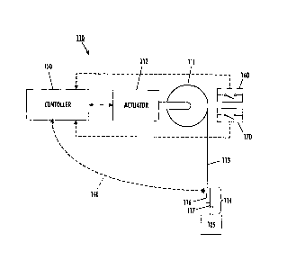
[0013] FIG. 1 is a schematic illustration of an exemplary
embodiment of the
present invention;
[0014] FIGS. 2-4 are illustrative representations of various
alternative
embodiments (e.g., differing load capacities) of an actuator drive assembly in
accordance with various common design aspects of the embodiments disclosed;
[0015] FIGS. 5 and 6 are exemplary representations of a planetary
gear
assembly illustrating alternative embodiments suitable for different load
capacities;
[0016] FIGS. 7A-C and 8-11 are illustrative representations of an
improved
load-sensing system employed as an aspect of the disclosed embodiments,
wherein
a load cell is used to sense the applied load via rotation of the drive
assembly relative
to the suspending structure;
[0017] FIGS 12A and 12B are alternative embodiments of operator
interface
devices employed in accordance with the disclosed invention;
[0018] FIGS. 13A-13C are illustrative examples of the components
and
operation (FIGS. 13A, 13B) of the operator interface device depicted in FIG.
12A;
[0019] FIG. 14 is an illustration of a slip-ring assembly suitable
for the
conduction of electrical signals as well as air (fluid) to the operator
interface device of
FIG. 12A;
[0020] FIGS. 15A-B and 16 are detailed representations of
alternative
embodiments of the operator interface devices of FIGS. 12A-B;
[0021] FIGS. 17 ¨ 19 are detailed illustrations depicting an
embodiment of
the present invention directed to sensing of the potential for a slack
condition of the
wire rope in accordance with an aspect of the present invention;
- 5 -
CA 2919247 2017-07-25
CA 02919247 2016-01-28
[0022] FIGS. 20 ¨ 21 depict an alternative slack-sensing embodiment that
may be employed in accordance with the disclosed invention;
[0023] FIGS. 22-24 are detailed representations of improved cable
management and drum cover features, including slack prevention, in accordance
with an aspect of the present invention;
[0024] FIGS. 25 and 26 illustrate an embodiment wherein the cable gate
components of FIGS. 22-23 are used to sense cable travel limits; and
FIGS. 27-29 illustrate an alternative embodiment for sensing cable travel
limits
employing the gates of FIGS. 22 and 23.
BEST MODE FOR CARRYING OUT THE INVENTION
[0025] To follow is a description intended to provide information related
to
each of the various improvements to an electric lift actuator and has been
described
with respect to embodiments thereof. It will, however, be appreciated that
several of
the improvements may be used with or implemented on other types of actuators
or
other load-handling equipment in general and are not specifically limited to
an electric
actuator or lift system as described herein. The drawings are not intended to
be to
scale and some features thereof may be shown in enlarged proportion for
improved
clarity.
[0026] Referring to FIG. 1, there is depicted a schematic representation
of an
embodiment of the invention, showing a take-up or drive pulley and associated
mechanical assemblies in an exemplary human power amplifier 110. At the top of
the device, a take-up pulley 111, driven by an actuator 112, is attached
directly to a
ceiling, wall, or overhead crane, arm or similar structure (not shown).
Encircling
pulley 111 is a line or cable 113 having one end attached to the pulley and
the
opposite end free for attachment to a load. Cable 113, also referred to as a
wire
rope, is capable of lifting or lowering a load 125 when the pulley 111 turns.
Line 113
can be any type of line, wire, cable, belt, rope, wire line, cord, twine,
string, chain or
other member that can be wound around a pulley or drum and can provide a
lifting
force to a load. Attached to line 113 is an end-effector 114, that includes a
human
interface subsystem (e.g. a handle or pendant 116) and a load interface
subsystem
117, which in this embodiment includes a removable J-hook, but may also
include a
pair of suction cups or similar load grasping means. Not shown, but included
in a
- 6 -
CA 02919247 2016-01-28
suction cup embodiment, would be an air hose for supplying the suction cups
with
vacuum.
[0027] In one embodiment, actuator 112 is an electric motor with a
transmission, but alternatively it can be an electrically-powered motor
without a
transmission. Furthermore, actuator 112 can also be powered using other types
of
power including pneumatic, hydraulic and other alternatives. As used herein,
transmissions are mechanical devices such as gears, pulleys and the like that
increase or decrease the tensile force in the line. Pulley 111 can be replaced
by a
drum or a winch or any mechanism that can convert the rotational or angular
motion
provided by actuator 112 to vertical motion that raises and lowers line 113.
Although
in this embodiment actuator 112 directly powers the take-up pulley 111, one
can
mount actuator 112 at another location and transfer power to the take-up
pulley 111
via another transmission system such as an assembly of chains and sprockets.
Actuator 112 preferably operates in response to an electronic controller 150
that
receives signals from end-effector 114 over a signal cable (not shown), wiring
harness or similar signal transmission means. It will be appreciated that
there are
several ways to transmit electrical signals, and the transmission means can be
an
alternative signal transmitting means including wireless transmission (e.g.,
RE,
optical, etc.). One embodiment of the present invention contemplates a custom
coil
cord 148 in which the coiled control wiring and/or air conduit are custom
molded so
as to permit such a cord to retain its shape (e.g., coiled around rope 113).
[0028] One or more sensors may be employed, in addition to the operator
controls to provide functional and/or safety features to the system. For
example,
controller 150 may receive input from sensors (e.g., switches) such as a slack
sensor
160, cable travel limit sensor 170, a load cell 1170 (e.g., Figs. 10, 11) or
an operator
presence sensor 1710 (FIG. 17).
[0029] In one embodiment the controller 150 contains three primary
components:
[0030] 1. Control circuitry including an analog circuit, a digital
circuit, and/or a
computer with input output capability and standard peripherals. The function
of the
control circuitry is to process the information received from various inputs
and to
generate command signals for control of the actuator (via the power
amplifier).
[0031] 2. A power amplifier that sends power to the actuator in response
to a
command from the control circuitry (e.g., a load cell indicating the force due
to the
- 7 -
CA 02919247 2016-01-28
-- load). In general, the power amplifier receives electric power from a power
supply
and delivers the proper amount of power to the actuator. The amount of
electric
power (current and/or voltage) supplied by the power amplifier to actuator 112
is
determined by the command signal generated within the computer and/or control
circuitry. It will be appreciated that various motor¨driver-amplifier
configurations may
be employed, based upon the requirements of the lift. In one embodiment, the
preferred motor-drive system is the ACOPOS Servo Drive produced by B&R
Automation under manufacturer's part no. 8V1016.50-2. One embodiment further
contemplates the addition of other modules used in conjunction with this
drive, such
as a CPU (e.g., ACOPOS 8AC140 or 8AC141), I/O Module (e.g., 8AC130.60-1) and
similar components to complete the controls.
[0032] 3. A logic circuit composed of electromechanical or solid state
relays,
switches and sensors, to start and stop the system in response to a sequence
of
possible events. For example, the relays are used to start and stop the entire
system
operation using two push buttons installed either on the controller or on the
end-
effector. The relays also engage a friction brake (not shown) in the event of
power
failure or when the operator leaves the system. In general, depending on the
application, various architectures and detailed designs are possible for the
logic
circuit. In one embodiment, the logic circuit may be similar to that employed
in the G-
force lift manufactured and sold by Gorbel, Inc.
[0033] As described in detail in U.S. Patent 6,622,990, human interface
subsystem 114 may be designed to be gripped by a human hand and measures the
human-applied force, i.e., the force applied by the human operator against
human
interface subsystem 114. In one embodiment, the human-applied force is
detected
by a load cell 1170 (e.g., FIGS. 10, 11) or similar output-generating sensor
as
described in more detail below, wherein the signal output level generated by
the load
sensor is a function of the load applied to the end-effector by the human and
is
added to or subtracted from the load being supported.
[0034] Load interface subsystem 117, as will also be described below is
a
removable or customizable mechanism designed to interface with a load, and
contains various holding, clamping or other customized load gripping devices.
The
design of the load interface subsystem depends on the geometry of the load and
other factors related to the lifting operation. In addition to the hook 117,
other load
interfaces could include suction cups as well as various hooks, clamps and
grippers
- 8 -
CA 02919247 2016-01-28
and similar means that connect to load interface subsystems. For lifting heavy
'-
objects, the load interface subsystem may comprise multiple load interfaces
(i.e.,
multiple hooks, clamps, grippers, suction cups, and/or combinations thereof).
[0035] Having described the components of a lift system, attention will
now
be turned to the various aspects of the present invention. One aspect is what
is
referred to as a "building block design" for the actuator system. The building
block
design is generally depicted in FIGS. 2 through 6, where various aspects of
the
design are set forth. In the creation of the building block design the various
components of a lift system (e.g., actuator, handle, gear reducers, etc.) are
designed
such that the components may be used on a plurality of models or types of
lifts (Easy
Arm TM, G-Force TM, etc.). Recognizing that in some situations characteristics
such as
lift capacity must be configured per order, the designs were also analyzed to
determine which, if any, components may be employed as common or universal and
which must be selected on a per-order basis.
[0036] One such example is depicted in FIGS. 2 ¨ 4. In FIG. 2, for
example,
the motor 210 and an associated reducer 212 are employed, and either or both
components may be used across several actuators having a range of lift
capacities ¨
for example as depicted in FIGS. 3 and 4. On a lower capacity unit a drum
pulley
integral adapter 216a is attached to the motor/reducer assembly. No additional
reduction in used. Referring also to FIGS. 3 and 4, attached in place of the
drum
pulley integral adapter 216a is an alternative (FIG. 3) or an additional (FIG.
4) speed
reduction means in the form of reducers 216b and 216c, respectively. The
additional
reducer 216b is designed/sized (e.g., internal planetary gear assembly 218;
FIG. 5)
so as to permit the motor 210 to lift an increased load weight. Referring also
to FIG.
4, a reducer 216c is attached, wherein the additional reducer employed is
designed/sized so as to permit the motor 210 to lift loads within another
range. In
this manner, the universal motor may be employed across a plurality of
actuator load
ranges, whereby the primary component being added/changed is the additional
reducer(s).
[0037] As will be appreciated, the embodiments depicted utilize a stacked,
building block gear reduction configuration, wherein the reducer assemblies
216a,
216b and 216c differ in load carrying capacity because the internal planetary
gearing
218 has ratios that are varied between the different models. For the lowest
lift
capacity, a simple adapter is used in lieu of additional reduction. For the
heaviest
- 9 -
CA 02919247 2016-01-28
. .
capacity, a second or "stacked" reducer is added, and the design of the second
reducer is selected as a function of the capacity desired for the lift
actuator. Also, as
different or alternative reducer (and planetary) assemblies are employed, the
controller is similarly altered or re-programmed so as to appropriately adjust
the
motor drive characteristics to accommodate the alternative reduction
capabilities of
the assemblies and direction of motor rotation.
[0038] It will be appreciated that the actuator drive
designs depicted in FIGS.
2 ¨ 6 enable the mass production, yet customization, of the actuator unit for
a
specific application, and further facilitates efficient service as well as a
more cost
effective design in lower volumes. As is also depicted in FIGS. 5 and 6,
several
embodiments include the reduction gearing inside the drum pulley 111. The
planetary gear reducers 218 are located inside the wire rope drum pulley 111,
which
saves space, weight and cost in contrast to conventional systems that place
the
reducer in-line with the drum. It also improves the balance of the actuator as
it is
suspended from an external structure such as a crane girder. With the reducer
inside
the drum the unit is compact, and the unit weight is reduced slightly due to
less drum
material. The cost of the reducer may also be reduced by producing the drum
from
conventional tubing versus a solid block of material which is machined. For
example,
in one embodiment, the drum may be manufactured from an aluminum alloy, or
alternatively from a nylon or similar polymer compound providing suitable
mechanical
characteristics.
[0039] As will be appreciated by those knowledgeable in the
field of lift
systems, an important aspect of the various embodiments disclosed herein is
the
reduction in the weight of such systems. In order to practically increase the
lifting
capacity of a lift, one must also consider the impact of the increased
capacity on the
supporting structure for the lift (e.g., trusses, cantilever arms, trolleys,
etc.). Thus,
while it may be possible to provide increased lifting capacity, it may be
necessary to
decrease the weight of the lifting equipment itself in order to obtain an
advantage
from the increased capacity. For example, if lift capacity can be increased by
25 kg,
in order to utilize the improved lift, it is necessary to assure that the
supporting
structure can handle the increased capacity, or the overall weight supported
by the
structure must be decreased. It is the latter point that is addressed by
various
aspects of the embodiments disclosed herein. Reduction of actuator weight
permits
greater use of the supporting structure's capacity for load weight. Moreover,
- 10 -
CA 02919247 2016-01-28
decreased actuator weight makes it easier to move the lift around (less
operator
effort (manual) or smaller motors (trolley)).
[0040] Turning next to FIGS. 7A-C and 8 through 10, depicted therein are
further components of an embodiment of the actuator 112 in which the load
supported by the actuator may be directly sensed using a compressive load
cell.
Actuator 112 further includes an arm 710 or similar structure and sleeve 712
which
are operatively connected to one another and to the drum pulley 111. In one
embodiment the arm 710 is attached to the sleeve so as to provide surfaces to
actuate the load sensing and slack sensing features disclosed herein, and to
provide
for positive rotational stop during a slack condition. As illustrated, for
example in FIG.
9, the sleeve 712 further supports the additional reduction and the drum
pulley 111
having a wire rope or cable 930 wound thereon, with one end attached to the
drum
pulley 111.
[0041] In one embodiment, the actuator 112 also utilizes an ultra-high
molecular weight (UHMW) polymer wear ring 999 (the doughnut-shaped aperture at
the bottom of the actuator thru which the wire rope 930 passes). Use of the
wear
ring results in a higher durability when compared to conventional actuators.
In
another embodiment, it will be appreciated that alternative designs of the
actuator
may alter the manner in which the supporting brackets (e.g. arm 710) are
connected
to the actuator drive components and/or the covers and housings as depicted in
FIG.
8. For example, the design depicted in FIG. 10 employs a slightly different
arm and
related support structure in the actuator.
[0042] The actuator 112 further includes the center casting 840, whereby
the
drum or additional reduction of the actuator drive assembly is supported
therein by
bearings 844, but where the drive assembly, including drum pulley 111, sleeve
712,
coil cord support and arm 710, is capable of rotational, albeit constrained,
motion
relative to the center casting as will be appreciated as required in order to
employ the
load cell to sense the load at the actuator (rotation of the actuator drive
components).
Actuator 112 further includes, as depicted in FIG. 8, a support member 850
connected to center casting 840, to suspend the actuator from its supporting
structure - such as a trolley or arm (not shown) - as well as a case or
housing 860
(shown as cutaway in FIG. 8) to enclose the operational components of the
actuator.
One embodiment of a housing suitable for the depicted actuator is found, for
example, in US Design Patent Application 29/256,812.
-11-
CA 02919247 2016-01-28
[0043] It will be appreciated that in addition to the molded covers,lt may
be
possible to further reduce the cost of the actuator 112 by employing less
expensive
covers. For example, covers or cover components made of formed sheet metal or
plastics and stock material shapes may result in significant reductions.
Moreover,
current sheet forming techniques permit the formation of somewhat complex
shapes
similar to those partially depicted in FIG. 8 and in the above-identified
design
application. In one embodiment employing formed metal covers, the gates or
apertures remain the same, but the remainder of the cover may be altered in
design
so as to accommodate alternative materials and forming techniques.
[0044] In addition to the improved, universal drive design, the drive and
control electronics, for example the ACOPOS Servo Drive , produced by B&R
Automation under manufacturer's part no. 8V1016.50-2, further provides
improved
input/output capability and enables further design improvements characterized
as
plug and play components. The plug and play characteristics of the various
components ¨ actuators, handles, etc. permit the lift controller (not shown)
to
recognize what type of handle has been attached to the lift, and to adjust any
programmatic controls or I/O so that the detected component works properly
with that
handle. The plug and play design overcomes difficulties observed in
conventional lift
systems when mechanical and electrical alterations must be made when changing
from one handle type or actuator type to another, thereby avoiding time
consuming
and costly modifications, and permitting the possibility of field alterations
and
upgrades.
[0045] Another feature enabled by an improved controller associated with
actuator 112 is remote diagnostic capability. In a remote diagnostic
embodiment, the
controller includes communication circuitry such that information may be
exchanged
between the actuator controller and another computing device (e.g., a
workstation,
crane controller, etc.) via a network connection (LAN/WAN/Internet). In
accordance
with an aspect of the present invention, the remote diagnostic capability
enables
remote configuration as well as troubleshooting of a lift device such as an
actuator.
[0046] For example, when a customer in Detroit has a problem with a
particular actuator, it would be possible to access the controller of that
actuator (with
a certain network IP address or similar identifier) from a remote location, or
at least to
receive data from the controller at the remote location, via Ethernet, a modem
and/or
the Internet, and to check and change settings as well as address any
performance
-12-
CA 02919247 2016-01-28
issues. The remote diagnostic and service capability is believed to
significantly
reduce the cost of maintaining and servicing the systems as it is not
presently
possible to accomplish lift service or address performance problems without
typically
having a technician travel to the work site or have the actuator shipped back
for
service. This will greatly reduce the downtime of the unit. It is anticipated
that the
controller will utilize a standard communication protocol such as CANbus as
well as
other well-known digital communication technologies and protocols, and will at
least
be able to execute and log rudimentary diagnostic functionality including
transmission
of log information and performance records, among others.
[0047] As described
above, the design of the actuator 112 is such that the
drive assembly is able to rotate relative to the center casting 840. Such a
design
facilitates the use of a compressive load cell 1170 as depicted in more detail
in FIGS.
and 11. In a conventional load-balancing lift, the load cell is typically
embedded
within or associated with the control pendant or end-effector, where the load
is
applied or attached. Such systems, however, require the use of more complex
load
sensors (tensile and compressive sensing), and further require the timely and
accurate transmission of signals back to the actuator controller in order to
control the
load. They also require a more complex and costly interlocking load cell
design to
provide reasonable safety should the pendant-based load cell fail. Mounting
compressive load cell 1170 on the drum center casting 840, permits sensing of
a
rotational force applied to arm 710, the rotational force being created by a
load
suspended on the free end of cable 930. Locating the load cell in the actuator
enclosure, adjacent to the control systems also provides for a shorter
transmission
path and improved signal quality received by the controller 150 (FIG. 1).
[0048] Taking the
load cell out of the load path also improves the safety of lift
devices because should the load cell fail, the load will not necessarily fall.
Hence,
the design depicted in FIGS. 10 and 11, enables sensing of the load at a
location
adjacent to the drive assembly, and without making the load cell a "link" in
the lift
system. In the drive assembly (e.g., drum pulley 111, reducing gearbox 212,
adapter/additional reduction (216a, b or c) and motor 210) the components of
the
assembly rotate axially on rolling bearings 844. An actuation surface 1174 is
associated with arm 710, and arm 710 is in turn assembled to sleeve 712 that
is
bolted to a mounting face of the gear reducer 212. The compression style load
cell
1170 is rigidly attached to the center casting 840 of the hoist, and is
situated to sense
-13-
CA 02919247 2016-01-28
the force applied by the actuation surface 1174. As the operator manually
applies
force to a suspended load, the drive mechanism rotates in the direction of
arrow
1178 and changes the force applied to the load cell. The heavier the force,
the
greater the compression sensed by the load cell, and visa versa. As depicted
in FIG.
11, the force sensor may include a small biasing spring 1150 at the end of
load cell
shaft 1145 that "balances" the dead weight of the cable and/or pendant away
from
the load cell, and as described below is important for slack-sensing as well.
In an
alternative embodiment, the present invention contemplates the derivation of
the load
applied to the cable, or pendant suspended therefrom, by monitoring the motor
current through the controller and associated software.
[0049] A further improvement to the lift actuator may include load cell
signal
conditioning. In addition to processing the load cell signal in order to make
the signal
useful for the present application, it is further contemplated that a single
conditioning
circuit may be employed for the load cell signal, wherein up to three or more
load
cells may be employed (e.g., three different load ranges) and a common or
universal
conditioning circuit may be used. Again the alternative to the universal
signal
conditioning approach would be to have separate circuits to handle the
different load
cells and the output signals they generate in response to the load suspended
from or
applied to the cable.
[0050] Referring next to FIGS. 12A-B and 13A-C and 14, depicted in FIG.
12A is an improved electro-mechanical mechanism for determining operator
intent in
the control pendant 116. As an alternative, a pendant such as that depicted in
FIG.
12B may be employed to control the present invention. Aspects of such a
pendant
are disclosed in published US Application 2005/0207872A1, filed March 21, 2005
by
M. Taylor et al. (USSN 11/085,764). Both devices may employ various signaling
devices (visual, audible, vibrational), and may include a liquid crystal or
similar
display means 3610 for indicating a current operating state or other
information for
the operator.
[0051] In the embodiment of FIG. 12A, as further illustrated in FIGS. 13A-C
the sensing mechanism employs a coil arrangement 1310, as compared to the
traditional linear variable-displacement transducer (LVDT). In the embodiment,
the
coil is used to sense a core, consisting of a metallic rod or similar
component, therein
and to sense operator intent (lifting or lowering). A further modification in
the
depicted embodiment is the use of flexible filament 1320 for attaching the
core to the
-14-
CA 02919247 2016-01-28
sliding portion of the handle, operator grip 1716. The use of a custom coil
arrangement is believed to be a less expensive alternative to the commercially
available LVDT. Moreover, the use of a flexible filament (e.g., nylon or
similar plastic
or flexible material) to connect the core to the handle prevents shearing the
core off
under use situations where the handle is over-torqued or rotated under load as
well
as preventing drag on the system if not perfectly aligned. It is also possible
to
employ LVDT or magnetic sensing devices to determine the downward or upward
operator inputs illustrated by FIGS. 13A and 13B, respectively. The
embodiments
depicted in FIGS. 13A and B illustrate the respective motion of the handle
(lower
large arrow), relative to the coil.
[0052] Alternative means for sensing operator input via the handle are
described, for example, in US patent 6,386,513 to Kazerooni for a "HUMAN POWER
AMPLIFIER FOR LIFTING LOAD INCLUDING APPARATUS FOR PREVENTING
SLACK IN LIFTING CABLE," issued May 14, 2002, and W02005092054, for an
"ELECTRONIC LIFT INTERFACE USING LINEAR VARIABLE DIFFERENTIAL
TRANSDUCERS," published October 16, 2005. In one embodiment, the control
pendant may be similar to that depicted, for example, in co-pending US Design
Application 29/256,811.
[0053] Another aspect of the improved control pendant is depicted in FIG.
14,
where a slip ring has been designed to permit the accurate and reliable
transmission
of the output from the coil sensor 1320 as well as the power switch 1610 or
related
electrical signals present in electrical connector 1624, up to the actuator
112 via the
control coil cord cable that may be plugged into connector 1628. The design
utilizes
a pancake-style slip ring assembly 1620, in the control handle, to allow 360-
degree
continuous rotation, independent of the wire rope and controls coil cord
cable. The
custom slip ring passes the electrical signals from the rotating handle up to
the
control coil cord cable. The custom slip ring assembly is also specifically
designed to
allow for air (pneumatic and/or vacuum) or other pressurized fluid access
through its
center via a swivel inlet 1640. This permits the operator to run air power to
the end
tooling, and still rotate 360 degrees continuously.
[0054] It will be appreciated that slip ring contacts are known, but it is
believed that the design of an integrated electrical and air conduit that
facilitates
unrestricted rotation is an improved aspect of pendant design not previously
employed in lift technology. The air conduit preferably enables the
transmission of a
-15-
CA 02919247 2016-01-28
pressurized fluid (e.g., pneumatic, vacuum, hydraulic) to a tool associated
with the
pendant. The improved design further controls or reduces acceptable "headroom"
in
the pendant at a reasonable cost.
[0055] Referring to FIGS. 13A-C, there is illustrated a further aspect of
the
pendant design, wherein the presence of the operator (hand on handle) is
sensed
using an inductive, or preferably a reflective photoelectric sensor 1710. In
one
embodiment, sensor 1710 is a tubular photoelectric sensor (metal, 12mm, PNP)
and
an indicator light on the sensor switches when it detects the reflected light
to indicate
an operator's hand is present. It will be appreciated that various alternative
types of
dead-man switches are known, however, many of these require a firm grip or
prolonged grasping of the operator grip 1716, which may lead to operator
fatigue as
well as confusion. The design depicted in FIGS. 13A-C illustrates a
photoelectric
sensor as a means of sensing the hoist operator's hand when engaged with the
control handle, requiring no interpretation on the user's part, avoiding the
tendency
for users to use the switch as a means to turn the unit on and off. When
engaged,
the sensor sends a signal back to the controller that then allows the hoist to
be
operated in the up and down direction. Alternative sensors or switches for
detecting
the operator's hand include a mechanical style roller switch similar to known
designs,
a touch sensor, an inductive optical sensor, and a membrane sensor. As will be
appreciated, locating the sensor within the body of the pendant is preferable
to avoid
damage or tampering, however, the pendant handle must then include an aperture
1730 through which the presence of the operator's hand can be sensed.
[0056] In various uses of an actuator and control pendant, it is sometimes
necessary to change or alter the load interface in the field. For example,
instead of a
hook, the load may need to be lifted using a threaded connector or the like.
Referring to FIGS. 15A-B, the design depicted therein contemplates a quick-
disconnect adapter on the bottom of the pendant or end-effector 116, wherein
an
operator may quickly change out end tooling by sliding down a collar 1810 that
retracts locking pins 1820, and allows the tool mounting shank 1830 to
release.
Another tool can then be quickly and easily attached by sliding its mounting
shank up
into the mounting hole, retracting the locking pins as it passes and then
securely
locking into place when the pins engage the grooves 1834 on the shank. No
tools
are required for end tooling changes.
- 16 -
CA 02919247 2016-01-28
[0057] It will be aripreciated by those familiar with lift systems that
the known
threaded coupling technique may be employed, or that alternatives requiring
the
operator to physically remove a pin 1910 (FIG. 16) in order to release the
tooling may
be included within the scope of the various embodiments described herein.
[0058] Referring next to FIGS. 17-21, there are depicted aspects of an
embodiment of the present invention incorporating an improved cable slack-
sensing
capability. In particular, as alluded to above relative to the improved load-
sensing,
the actuator embodiment depicted in FIGS. 17-21 senses cable slack using the
rotation of the drum, gear reduction and motor (drive assembly) as well
(albeit in the
opposite rotational direction). In this design, the main drive assembly (drum
pulley
111, gearbox (not shown) and motor 210) rotate axially on rolling bearings
844. An
actuation plate or arm 710 is assembled to a sleeve that was bolted to the
mounting
face of the primary gearbox, and also rotates along with the drive assembly.
When
the operator removes all weight, excluding the control handle and any
applicable
tooling from the wire rope 930, slack is induced. When slack is induced, the
drive
assembly rotates in a counter-clockwise direction (arrow 2020), aided by the
use of
an compression spring 1150 (FIG. 11). Provisions for adjustment of the spring
force
will be required to facilitate variations in customer applied tooling. The
compression
spring 1150 is mounted between the load cell 1170 and surface 1174 of the
actuation
plate and is coaxial on a load pin or shaft installed in the load cell. When
the drive
assembly rotates under unloaded or slack conditions, a micro switch 2030,
mounted
to the main support frame of the hoist senses the presence of the actuation
plate
(FIG 24) by contact with the actuation plate at 2034. When the micro switch is
activated, it sends a signal to the controller (not shown) whereby the
software will
only allow the hoist to move in the upward direction. For the safety of the
user, once
slack is sensed, the controller will not allow the hoist to feed out any
additional wire
rope in the downward direction.
[0059] As will be appreciated, the use of the rotating drive assembly for
the
purposes of load and slack sensing permits the load sensing device to 'see"
any
torque loading and thereby be able to sense all the load that both the wire
rope, and
the coil cord/ air hose would see. In other words, the load sensor will have a
compressive load applied to it that is the direct result of the weight of the
load. Also
as the load is raised or lowered, the cumulative load remains the same, even
though
the relative portions of the load carried by the coil cord, air hose, and wire
rope can
-17-
CA 02919247 2016-01-28
vary. Since the entire wire rope and coil -cord assembly are supported from
the
rotational drive assembly, the load cell senses their entire weight at all
times, thus
variations in load height does not affect load sensing or float mode
operation. Any
potentially detrimental affects, for example on float mode, of the spring
force and
weight of the coil cord are negated by this mounting configuration.
[0060] In alternative embodiment, it may be possible to sense slack
utilizing
software to monitor the current of the motor to determine a slack condition.
Although
possible, it remains a concern that such a method may prove to be unreliable.
It is
also contemplated that instead of the mechanical, contacting switch (roller
switch or
the like) a non-contacting proximity sensor 2040 may be employed to sense the
rotation of the plate 710. Such an embodiment is depicted, for example, in
FIGS. 20
and 21, where sensor 2040 is employed to sense the rotation of plate 710 to
determine the slack condition.
[0061] Attention is now turned to several additional aspects of the
improved
actuator 112, which includes a drum pulley and wire rope (cable) guide
arrangement.
Referring to FIGS. 22 through 29, the improved design utilizes a two-piece
assembly
2610 (2610a, 2610b, etc.) that clamps or assembles around the wire rope or
other
lifting medium, and slides back and forth on rails provided by the drum cover
998
(FIG. 25). The sliding motion for assembly 2610 is induced by threads 2620
contained on one half of the assembly, 2610a that runs in the open grooves
2622 of
the wire rope drum pulley 111.
[0062] Assembly 2610, when assembled about the rope 930, provides a
sliding gate or aperture through which the wire rope 930 departs from the drum
as
depicted in FIG. 24. Such a device, in addition to the function of protecting
the cable
and the drum, also prevents any side wear on the drum grooves and keeps the
wire
rope tightly constrained on the drum pulley, thus avoiding the creation of
unwanted
slack. In other words, the wire rope's side forces are taken by the gate and
the cable
is not prone to wearing the drum surface because the alignment at entrance to
the
drum grooves is nearly perfect in all cases. The large bearing area of the
threads on
the gate 2610a provides great lateral force, and distributes this force over
many
grooves in the drum, since any lateral force is only likely to occur when the
wire rope
is nearly fully out, and the engagement of the gate and the grooves of the
drum is at
its maximum number of threads on the gate. Having this half of the gate
permanently
attached to the drum allows it to maintain registration when replacing the
wire rope.
-18-
CA 02919247 2016-01-28
[0063] Another feature of this embodiment is depicted specifically in FIGS.
24-29, where the sliding gate 2610 allows the gate itself to be employed as an
indicator of the upper and lower travel limits for the cable. As depicted by
the
dashed-line arrows in FIGS. 25 through 28, the gate slides back and forth
driven by
the drum pulley rotation as the wire rope is being wound and unwound
therefrom.
The addition of the limit switches 2510 depicted in FIGS. 25 and 26, for
example,
permit the motion of the gate 2610, transmitted through a rod 2520, or similar
member, to be used to identify travel limits. As described below, the design
allows
the setting of limit switches to be unaffected by changes to the system,
replacement
of the wire rope, etc. In fact, only the side of the gate nearest the anchored
end of
the wire rope, 2610b, has to be removed to change the rope, even though the
limit
switch for maximum wire rope out has to be bypassed for the reloading
operation. It
will be appreciated that a more conventional ball screw drive mechanism, to
move
the wire rope drum pulley back and forth may be employed, or that a mechanism
that
gears or operatively drives an idler pulley via a single groove on the drum
pulley may
be used as is the case in many current Gorbel actuators.
[0064] Referring specifically to FIGS. 25 and 26, depicted therein is a
limit
sensing system employing micro switches 2510 as noted briefly above. Depicted
is
an embodiment that consists of a rod 2520 which is moved back and forth as a
result
of movement of the threaded gate (gate 2610a). On the rod are contained two
adjustable cylinders 2530 which can moved to the desired location and then
fixed in
placed, e.g., with a locking nut or similar means). These cylinders contact
the micro
switches 2510 when the gate is in its upper and lower limit locations, As the
wire
rope guide or gate mechanism slides back and forth, and the cylinders trigger
the
sensor 2510, a signal is sent to the controls to activate either the upper or
lower
travel limit of the unit. When a travel limit is triggered, the software will
then only
allow the hoist to operate in the direction opposite of the triggered target
(i.e. if the
upper limit is triggered, the hoist will only operate in the down direction).
The limits
may be adjusted by moving the cylinders.
[0065] Although the micro switch mechanism is believed to be preferred, by
virtue of its simplicity, it should be appreciated that alternative sensing
systems such
as a magnetic, non-contacting sensor may eliminate the contact force required
to
actuate the sensor and thus eliminating component wear may be employed. For
example, as depicted in FIGS. 27-29, a magnetic sensor 3410 may be mounted
-19-
CA 02919247 2016-01-28
stationary to the fixed wire rope drum cover 998. Along with two magnetic
targets
3420 and 3422, that mount to the wire rope guide mechanism 2610, the sensor is
operatively connected to the drum pulley. The sensor targets 3420, 3422
consist of
one north and one south pole oriented magnet, and are suitable for similarly
providing travel limit signals as discussed above. Other options for travel
limit
sensors include optical or other non-contact techniques, as well as
conventional
mechanical sensors and switches.
[0066] The various features and functions disclosed herein are preferably
implemented using a controller or similar processing system suitable for
operating
under the control of programmatic code. One embodiment contemplates controller
150 (FIG. 1) having pre-loaded functionality for a wide range of features and
functions, wherein one or more features and functions are enabled only as a
result of
a subsequent instruction or signal to the controller. In this way, the
universal nature
of the actuator 112 (including controller 150), may be further extended. The
process
or operation of preloading all software functionality and then only enabling
what the
customer wants or purchases, is believed to facilitate the intended
interchangeability
of components in accordance with an aspect of the present invention. Such a
process would also allow the enablement of increased functionality after an
actuator .
has been deployed in the field ¨ for example when a customer's needs or
application
changes, the actuator can have additional features or functions enabled. It is
also
possible that in the event that a plug and play component was later attached
to the
actuator, the actuator would not only recognize the component as described
above,
but could alter its programmatic controls to facilitate use of the newly
installed
component. It is believed that these improvements will permit rapid
customization of
actuators to customer's requirements, while reducing or eliminating the need
for
custom software changes and ongoing support.
[0067] Returning to FIG. 12A, depicted therein is a further improvement to
the operator control pendant or end-effector 116. In the embodiment depicted,
the
pendant 116 is fitted with a liquid crystal display (LCD) 3610 or similar
display
technology in order to provide the ability to communicate more readily-
available
information to a user. The information displayed in the LCD may include basic
information such as system status (i.e.: system ready for use), advanced or
optional
information such as load weight, system usage and service information (i.e.:
number
of cycles completed and system service indicators) as well as enhanced
guidance
- 20 -
CA 02919247 2016-01-28
and feedback when in programming mode such as what feature is currently being
programmed (i.e.: virtual limits).
[0068] By using the LCD it is possible to provide more and different
information to the installer, the user and even maintenance staff. Once again,
as an
alternative to the LCD display, conventional light-emitting diodes (LEDs) and
the like
may be employed to communicate actuator status information to an operator.
[0069] In yet a further alternative embodiment, for example as depicted in
FIG. 25, the wire rope is tightly constrained at all times between the drum
pulley 111,
the drum cover 998 and the sliding gates 2610, so that no space is available
to allow
a slack loop in the wire rope, anywhere in the actuator. Thus even a
compressive
load applied to the wire rope will not allow slack to form or accumulate
within the
actuator 112, as long as the anchored end is restrained from slipping out.
Practically
speaking, there is likely to be a small portion of the wire rope that remains
free while
inside the actuator and before exiting the gate, as it unwinds from the pulley
and
before exiting the actuator or drum housing. It will be further appreciated
that the use
of a larger diameter wire rope (e.g., 0.25 inch diameter rope helps in this
regard,
since it has more column strength than smaller diameter rope) reduces the
capability
of the rope for forming a loop (slack) when unconstrained for a short
distance. Those
skilled in the art will appreciate that the diameter of the rope is a function
of the load
capacity of the actuator and may be smaller or larger than 0.025 inches.
[0070] With additional functionality provided in the current controls, the
system may also perform one or more hardware identification processes during
power up, and may compare the resultant information against specified
functionality.
Using such information, the system may produce a warning message that can be
displayed if issues are found such as inoperative or missing subsystems, for
example, a missing handle or operator presence sensing being inoperative.
[0071] Again in view of the universal design intended for the various
embodiments characterized herein, the present invention contemplates the use
of a
real-time I/O port assignment thru a flexible configuration setup, rather than
modifying the source code program each time. Such a system would permit the
user
to access preprogrammed functionality within the controls to more rapidly
configure
the unit's I/O for their specific application. It is contemplated that a
software interface
may be provided to further simplify the ease and flexibility of application
configuration.
- 21 -
CA 02919247 2016-01-28
[0072] It will be
appreciated that various aspects of the above-disclosed and
other features and functions, or alternatives thereof, may be desirably
combined into
many other different systems or applications. Also that various presently
unforeseen
or unanticipated alternatives, modifications, variations or improvements
therein may
be subsequently made by those skilled in the art which are also intended to be
encompassed by the following claims.
- 22 -