Note: Descriptions are shown in the official language in which they were submitted.
CA 02919529 2016-01-26
WO 2015/021087 PCT/US2014/049844
SHRIMP-PROCESSING APPARATUS AND METHODS
BACKGROUND
The invention relates generally to shellfish processing and more particularly
to
apparatus and methods for removing the heads and shells from shrimp.
Originally introduced because of the high labor costs of peeling small shrimp
by
hand, shrimp-peeling machines are now widely used in the shrimp-processing
industry.
Roller-type peeling machines, in particular, dominate the bulk shrimp-peeling
industry. U.S.
Patent Nos. 2,778,055, Jan. 22, 1957, and 2,537,355, Jan. 9, 1951, describe
the basic structure
and principles of operation of roller-type shrimp peelers, which detach heads
and shells
from shrimp. But the fluids and slime squeezed from the heads of the shrimp
coat the
peeling rollers, which degrades their grip on the shrimp and peeling quality.
Deheading shrimp by hydrodynamic force is known from U.S. Patent No.
5,195,921,
Mar. 23, 1993. In that patent, a shrimp-laden fluid is pumped through conduit
that abruptly
narrows. The abrupt decrease in the cross-section of the conduit causes the
flow to accelerate
through the narrow cross section according to the Venturi Effect. Hydrodynamic
forces
caused by the change in cross-section tend to detach heads from shrimp.
Because of the
high-speed water flow and rollerless operation, the removal of heads is not
degraded by
shrimp fluids. As shown in FIGS. 1A and 1B, cold-water shrimp 10, for example,
have a
long, thin sixth segment 12 that is easy to damage. The joint 14 between the
third and fourth
segments is also susceptible to damage. The abrupt change in the cross-section
of the
conduit can cause shrimp to break at these and other weak spots.
Thus, there is a need for a shrimp-processing system that can dehead and shell
shrimp without damaging shrimp meats.
SUMMARY
A system embodying features of the invention for processing shrimp comprises a
hydraulic head detacher including one or more venturis that accelerate a flow
of fluid
carrying shrimp to subject the shrimp to turbulence detaching heads from the
bodies of the
shrimp. A peeler detaches shells, appendages, and residual heads from the
headless shrimp
bodies received from the hydraulic head detacher. An inspection station
receives the shrimp
bodies from the peeler and redirects those with residual shell or appendages
back to the
peeler.
1
CA 02919529 2016-01-26
WO 2015/021087 PCT/US2014/049844
In another aspect of the invention, a method for processing shrimp comprises:
(a) detaching heads from the bodies of the shrimp by flowing a fluid carrying
the shrimp
bodies through one or more venturis; (b) peeling the headless shrimp bodies to
remove the
shells from the shrimp meat; and (c) inspecting the headless shrimp bodies for
residual shell
and appendages and repeating step (b) on headless shrimp bodies having
residual shell or
appendages.
In yet another aspect of the invention, a system for processing shrimp
comprises a
hydraulic head detacher and a hydraulic shell detacher. The head detacher
includes one or
more venturis that accelerate a flow of fluid carrying shrimp. The venturis
subject the
shrimp to turbulence that detaches heads from the bodies of the shrimp. A
hydraulic shell
detacher includes one or more venturis that accelerate a flow of water
carrying headless
shrimp to subject the shrimp to turbulence that detaches shell from the bodies
of the shrimp
received from the hydraulic head detacher.
In another aspect of the invention, a system for processing shrimp comprises a
hydraulic shell detacher and an inspection station. The shell detacher
includes one or more
venturis that accelerate a flow of water carrying shrimp to subject the shrimp
to turbulence
that detaches shell from the bodies of the shrimp. The inspection station
receives the shrimp
bodies from the hydraulic shell detacher and redirects those shrimp bodies
with residual
shell or appendages back to the hydraulic shell detacher.
BRIEF DESCRIPTION OF THE DRAWINGS
These aspects and features of the invention are described in more detail in
the
following description, appended claims, and accompanying drawings, in which:
FIGS. 1A and 1B are side and top views of a shrimp;
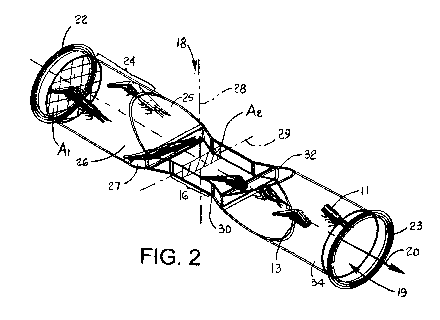
FIG. 2 is an isometric view of a venturi tube for a deheading apparatus
embodying
features of the invention;
FIGS. 3A-3C are side views of a venturi tube as in FIG. 2 with a tapered
transition
region with taper angles of 30 , 45 , and 60 ;
FIGS. 4A and 4B are front and rear isometric views of a deheading system
including
venturi tubes as in FIG. 2;
FIG. 5 is a schematic diagram of a multi-venturi deheading system using
venturis as
in FIG. 2;
2
CA 02919529 2016-01-26
WO 2015/021087 PCT/US2014/049844
FIG. 6 is a schematic diagram of a multi-venturi deheading system as in FIG. 5
including an additional boost pump;
FIG. 7 is a block diagram of one version of a shrimp-processing system
embodying
features of the invention including a venturi head detacher and a roller
peeler;
FIG. 8 is a block diagram of a second version of a shrimp-processing system
embodying features of the invention including venturi head and shell
detachers; and
FIG. 9 is a block diagram of a third version of a shrimp-processing system
having
features of FIGS. 7 and 8 and a reprocessing path selector.
DETAILED DESCRIPTION
A venturi tube, or venturi, usable in a shrimp-processing system embodying
features
of the invention is shown in FIG. 2. The venturi 16 is a restricted portion of
a conduit 18
enclosing a fluid channel 19 conveying a shrimp-laden fluid along a fluid path
20. The
conduit has an open entrance end 22 and an opposite open exit end 23
downstream of the
entrance end. An input portion 24 of the conduit extends downstream from the
entrance end
22 and defines the fluid channel with a cross-sectional area Ai.
A transition portion 26 of the conduit extends downstream from the input
portion 24
to the venturi 16. The transition portion 26 defines a length of the fluid
channel with a
converging cross-sectional area formed by two pairs of converging parabolic
walls: large
walls 25 and small walls 27. The venturi 16 has a cross-sectional area A2 that
is less than that
of the input portion 24. In the example of FIG. 2, the shape of the cross-
sectional area A2 of
the venturi is rectangular, but may be other shapes, e.g., elliptical or oval,
having a minor
axis 28 shorter than its major axis 29. The venturi 16 extends downstream to
an open end 30.
In FIG. 2, the venturi's end 30 opens into a downstream transition portion 32
of the conduit
defining a length of the fluid channel 19 diverging outward from the cross-
sectional area A2
of the venturi to a larger cross-sectional area of an output portion 34 of the
conduit. In this
example, the output portion 34 has the same cross-sectional area Ai as the
input portion 24.
Thus, the conduit 18 in FIG. 2 is reversible. But the downstream transitional
portion 32 may
be eliminated and replaced with a flat plate having an opening forming an end
wall of the
output portion 34 at the open end 30 of the venturi 16.
As shown in FIGS. 3A-3C, the transition portion of the conduit 18 may be
gradual
(FIG. 3A with a 30 taper of the long parabolic walls 25 relative to the
direction of the fluid
3
CA 02919529 2016-01-26
WO 2015/021087 PCT/US2014/049844
path 20 and a long length), sharp (FIG. 3C with a 60 taper of the long
parabolic walls 25 and
a short length), or intermediate (FIG. 3B with a 45 taper of the long
parabolic walls 25 and
an intermediate length). The sharp transition portion 26 of FIG. 3 causes a
more abrupt
acceleration of the fluid through the channel than the longer tapers of FIGS.
3A and 3B and
is more useful for sturdier shrimp. As indicated by the convergence of
streamlines 36 in the
transition portion 26 of the conduit, the flow accelerates to a higher speed
in the venturi 16.
The converging flow tends to orient the shrimp along the streamlines by
minimizing the
surface area broadside to the flow. The hydrodynamic forces caused by the
rapid
acceleration of the flow at the venturi and by the non-uniformity of the flow
just
downstream of the venturi is sufficient to detach heads from the shrimp. The
major axis 29
of the venturi cross-sectional area A2 is long enough to admit a major portion
of, if not all,
the length of a shrimp into the venturi without severe collisions with the
interior walls of the
conduit that could break the shrimp between segments. For this reason,
gradually tapered
venturis are especially useful for deheading fragile cold-water shrimp.
Sharper tapered
venturis are useful not only for deheading shrimp, but also for peeling, or
shelling, shrimp.
One version of a deheading system 40 is shown in FIGS. 4A and 4B. Shrimp are
conveyed out of a feed tank 42 by a conveyor belt 44 and dropped into a fluid-
filled
trough 46. A food pump 48 draws shrimp-laden fluid from the trough 46 and
pumps it into
a conduit system 50, which has two venturis 52, 53 at spaced apart locations
along its length.
Shrimp are deheaded in the venturis and conveyed by the fluid through the
conduit system
to a feed plenum 54. The shrimp bodies and detached heads drop from the plenum
onto a
screen slide 56. The fluid drains through the screen and into a tank 58 in
fluid
communication with the trough 46. A perforated plate 60 between the tank and
the trough
prevents shrimp in the trough from entering the tank 58. The food pump 48 is
driven by a
pump motor 62. Together, the pump and the motor form flow control means that
controls
the flow rate and the fluid speed through the conduit system. The deheading
system can
also be used to loosen or detach shells and appendages from the shrimp.
The deheading and shelling system shown in FIG. 5 has five venturis 64
cascaded in
series in a conduit system 66. A food pump 68 induces a flow through the
conduit system 66.
Such a multiple-venturi system can be effective for deheading and shelling
shrimp. The
deheading and shelling system of FIG. 6 adds fluid-pressure sensor 69 at
sensor locations in
the conduit system 66, for example, at locations just upstream of the final
four venturis 64 to
4
CA 02919529 2016-01-26
WO 2015/021087 PCT/US2014/049844
measure the hydrodynamic force of the flow. The outputs 70 of the pressure
sensors control
valves 72 connected between a boost pump 74 and fluid lines 76 injecting fluid
into the
conduit system at injection locations 78 near the sensor locations, for
example, to replace any
leaked fluid and to maintain the fluid pressure along the length of the fluid
channel.
One version of a shrimp-processing system embodying features of the invention
is
shown in FIG. 7. An infeed system 80 feeds raw head-on, shell-on shrimp to a
hydraulic
head detacher 82. The infeed system includes, for example, the feed tank 46
into which
shrimp are conveyed, the food pump 48, and the conduit 50 of FIGS. 4A and 4B
through
which the food pump pumps a shrimp-laden fluid, such as water, in a continuous
flow. The
hydraulic head detacher 82 comprises a single venturi (52, FIG. 4A) or a
cascade of venturis.
As shown in FIG. 2, the venturi detaches the loosely connected heads 11 from
the shrimp
bodies 13.
The detached heads flow to a collector 84 that collects the headless shrimp
bodies
and the detached heads conveyed through connecting conduit from the head
detacher 82.
One example of a collector includes the feed plenum 54 and the screen slide 56
of FIGS. 4A
and 4B. A conveyor 124 transports the detached heads and shrimp bodies to a
roller peeler
88. An optional water recirculator 86, which includes filters or other water
treatment
components such as the screen 56, the tank 58, the perforated plate 60, and
the feed pump 48
of FIGS. 4A and 4B and inlet valves to admit fresh water to replenish lost
fluid, recirculates
the filtered spent fluid back into the flow at the front end of the head
detacher 82. The roller
peeler 88, which may be a Laitram Model A peeler manufactured and sold by
Laitram
Machinery, Inc., removes the shells from the headless shrimp bodies and
discards the shells
along with the detached heads. The head detachment may be performed at the
same
location as the peeling or at different geographical locations. For example,
the heads may be
detached geographically close to where the shrimp are caught so that the
headless shrimp
can be shipped to a peeling operation for less cost because of the lower
weight of headless
shrimp and with less chance of spoilage because of the removal of head organs
and fluids.
The peeled shrimp are conveyed to a shell separator 90, which includes one or
more
cleaners or roller separators interconnected by conveyors or flumes. The shell
separator
separates loosened and detached shell and appendages from the peeled shrimp
meats,
which are conveyed to an inspection station 92. The inspection station 92 may
include a
machine-vision accept-reject sorter or be a manned inspection station in which
shrimp with
5
CA 02919529 2016-01-26
WO 2015/021087 PCT/US2014/049844
residual shell or appendages are sorted from the accepted peeled shrimp meats.
Rejected
shrimp are conveyed back to the roller peeler 88 for re-processing.
Another version of a shrimp-processing system is shown in FIG. 8, in which the
roller peeler 88 of FIG. 7 is replaced by a hydraulic shell-removal system.
The shrimp are
deheaded as in FIG. 7. The headless shrimp bodies exiting the headless shell-
on collector 84
are conveyed to a head separator 94, which can be an air separator or a manual
inspection
station. The headless shrimp bodies are culled from the detached heads and
transported to a
second infeed system 96.
Like the first infeed system 80, the second infeed system 96 can include a
feed tank,
in which the headless shrimp with loosened shell and appendages are
accumulated, a food
pump for entraining the shrimp in a fluid flow through a conduit leading to
another
hydraulic detacher 98 that is used to detach shell and appendages from the
headless shrimp
bodies. The hydraulic shell detacher 40 is similar to the hydraulic head
detacher 82. The
number of venturis, their velocity gradients, and their flow rates can all be
tailored to detach
shell and appendages without damaging the peeled shrimp meat.
The peeled shrimp are collected in a peeled shrimp collector 100. Like the
headless,
shell-on collector 84 downstream of the hydraulic head detacher 82, the peeled
shrimp
collector 100 can include a water removal screen, a collection tank, and an
outfeed conveyor
44. A water recirculator (not shown) may be used with the shell detacher and
separator. The
peeled shrimp collector drains the water from the shrimp meat and the detached
shell and
appendages. The shrimp meat and the detached shell and appendages are
transported to the
shell separator 90, which separates the shrimp meat from the detached shell
and
appendages. The headless, shelled shrimp bodies are then sent to the
inspection station 92.
Rejected shrimp with residual shell or appendages are returned to the headless
shrimp
infeed 96 for another pass through the hydraulic shell detacher 98.
FIG. 9 shows a shrimp-processing system with a roller peeler 88 followed by a
hydraulic shell detacher 98. Headless, peeled shrimp exiting the roller peeler
88 are
conveyed to an after-peeler infeed 97 like the first infeed 80 and the second
infeed 96 in the
processing system of FIG. 8. The headless, peeled shrimp are then subjected to
further
hydraulic shell detachment and separation in the shell detacher 98, the peeled
shrimp
collector 100, and the shell separator 90. The processed shrimp meats are
conveyed to the
inspection station 92. The rejected shrimp with residual material are
optionally returned to
6
CA 02919529 2016-01-26
WO 2015/021087 PCT/US2014/049844
the system for reprocessing. A reprocessing path selector 102 directs the
rejected shrimp
back into the roller peeler 88 or to the infeed 97 to the hydraulic shell
detacher 98 depending
on the amount of residual material on each processed shrimp.
7