Note: Descriptions are shown in the official language in which they were submitted.
CA 02920074 2016-02-01
WO 2015/018969 PCT/F12014/000018
METHOD FOR STEERING A DIRECTION OF A DRILLING DEVICE
DRILLING A HOLE INTO THE GROUND
Invention relates to a method for steering the direction of a drilling device
drilling a hole
into a ground wherein a hammering and rotatable bit is used as the drilling
bit and the
device comprises coupled to the bit a hammering device behind the bit and a
drill arm
potentially belonging to it wherein the rear part of the hammering device or
the drill arm
locates in the drilled hole or inside a casing tube in a free space which
casing tube coats
the drilled hole so that the mentioned rear part has space to move in the
direction of the
radius of the drilled hole and that the location of the bit in the ground
during the drilling is
observed on the grounds of the data received from the position sensors which
indicate the
location of the bit.
A solution as a control method of the direction of a drilling device is
previously known
from the publication EP 0369030 in which solution the front end of the
drilling device is
formed to be two successive, cylindrical units which units are connected with
each other
so that they form a little angle. The units can be bent due to the joint
construction in the
desired direction with the help of power units, such as hydraulic cylinders so
that the
whole unit starts to turn in this direction.
The disadvantage of this above described method is the fact that it is
suitable mainly only
for controlling the direction of the drillings which are performed into a soft
wound. The
foremost cylinder part can be turned for the control only in a ground which
gives in
enough so that this part can be turned in relation to the latter part. In a
rock hole this
turning is successful only in the case where a hole which has a clearly larger
diameter
than what the needed cylinder parts, which are needed for the control, are
regarding their
diameter, is being drilled with the bit. Additionally this method requires
either hydraulic
pipeworks or an electric cable which can be directed to the drill head and
several power
units which are related to the turning. Also the location of the drill head
needs to be
observed so that the alignment of the drill head can be performed.
Methods for controlling the direction of the drilling device are further known
also from
the publications US 20070187150, US 6808027 and US 4319649. In these
publications
the drilling devices are cutting drills which drill a hole into the ground
with which cutting
SUBSTITUTE SHEET (RULE 26)
2
drills one drills downwards and no impacts are directed to the bit. For
example
oncoming stones can cause angular deviations for the drilling devices. The
drill rods
are supported at the wall of the hole at several locations but the orientation
of the bit
at the head is not aimed to be turned with the help of the control of the
direction in
.. relation to the centre line of the drill rod, in other words one does not
aim to create
an angle between these directions. But the bit is being moved sideways and
also the
drill rod is being moved sideways with the help of several successive,
adjustable
support elements.
.. According to one aspect of the present invention, an object is to provide a
method
for controlling a direction of a drilling device which drills a hole into a
ground wherein
a hammering and rotatable bit is used as the drilling bit and the drilling
device
comprises coupled with the bit a hammering device behind the bit wherein a
rear
part of the hammering device is positioned in the drilled hole or inside a
casing tube
which covers the drilled hole in a free space so that there is space for the
rear part to
move radially within the drilled hole and that a location of the bit in the
ground during
the drilling is observed based on data received from a plurality of position
sensors
which indicate the location of the bit, wherein in the method the direction of
the
drilling is controlled by adjusting only the position of the rear part in
relation to a
centre line of the drilling device by adjusting a drill rod to rotate a
support element
which is located in the drilled hole or at an inner surface of the casing tube
to
position a hole defined in the support element such that the hole is deviated
from the
centre line or located on the centre line, said drill rod is adjusted at a
feed end of the
drilling device and wherein a direction angle is formed only for the bit and
for the
hammering device in relation to the centre line and that an impact which is
directed
to the bit is formed on a front side of the support element and the impact is
directed
in the direction of the bit onto the surface to be drilled.
Date Recue/Date Received 2020-11-16
2a
According to another aspect of the present invention, an object is to provide
a
method for controlling a direction of a drilling device which drills a hole
into a ground
wherein a hammering and rotatable bit is used as the drilling bit and the
drilling
device comprises coupled with the bit a hammering device behind the bit
wherein a
rear part of the hammering device is positioned in the drilled hole or inside
a casing
tube which covers the drilled hole in a free space so that there is space for
the rear
part to move radially within the drilled hole and that a location of the bit
in the ground
during the drilling is observed based on data received from a plurality of
position
sensors which indicate the location of the bit, wherein in the method the
direction of
the drilling is controlled by adjusting only the position of the rear part in
relation to a
centre line of the drilling device by adjusting a drill rod to rotate a
support element
which is located in the drilled hole or at an inner surface of the casing tube
to
position a hole defined in the support element such that the hole is deviated
from the
centre line or located on the centre line, said drill rod is adjusted at a
feed end of the
drilling device and wherein a direction angle is formed only for the bit and
for the
hammering device in relation to the centre line and that an impact which is
directed
to the bit is formed on a front side of the support element and the impact is
directed
in the direction of the bit onto the surface to be drilled, the support
element having a
first position on the centre line and a second position deviated from the
centre line.
Other possible aspect(s), object(s), embodiment(s), variant(s) and/or
advantage(s) of
the present invention, all being preferred and/or optional, are briefly
summarized
hereinbelow.
For example, in order to eliminate the disadvantages of the prior art methods
described above a new control method of the direction of the drilling device
is
developed for such a drilling device which drilling device comprises a
hammering
device behind its bit and a potential drill arm which belongs to the bit in
which case
Date Recue/Date Received 2020-11-16
2b
the rear part of the hammering device or the drill arm is located in the
drilled hole.
With the invention an essential improvement is achieved in relation to the
existing
prior art and it is characteristic of the method according to the invention
that in the
method the drilling direction is controlled by adjusting only the position of
the
mentioned rear part in relation to the centre line of the drilling by
arranging a support,
which is deviated from the centre line or is located on the centre line, for
the
mentioned rear part with the help of a support element by using the drilled
hole or
the inner surface of the casing tube which support is adjusted at the feed end
of the
drilling device and wherein a direction angle is formed only for the bit and
for the
hammering device in relation to the mentioned centre line and that the impact
which
is directed to the bit is formed at the front side of the mentioned support
element and
that the impact is directed in the direction of the bit a into the surface to
be drilled.
The advantage of the method according to the invention that it is suitable for
ground
drilling as well as for drilling a hole into a rock when the alignment of the
bit and a
minor turning into deviating angle related to it can be performed inside the
drilling
device. The bit of the drilling device which bit is located exactly at the
very drill head
turns only a little and the percussion hammer which is located behind the bit
and a
potential drill arm turn in a free space inside the casing tube or in the rock
hole.
Support elements can easily be made for the rear part of the percussion hammer
or
the drill arm with the help of which the rear part can be kept either on the
centre line
of the drilling or in an angle position which deviates from it. The percussion
hammer
hammers the bit always in an efficient
Date Recue/Date Received 2020-11-16
CA 02920074 2016-02-01
WO 2015/018969
PCT/F12014/000018
3
hammering direction without losses even though the bit would be turned in
relation to the
centre line of the drilled hole.
In the most advantageous implementation method of the invention the drill head
does not
comprise power units which are related to the control and does not comprise
pipe-work or
cabling when the functions related to the alignment can be performed at the
feed head of
the drilling device, at the ground surface with an axial movement of the drill
rod and with
the help of a rotation or just by using the rotation in which case one can
rotate the drill rod
and/or the casing tube.
to In the following the invention is described more detailed by referring
to the
accompanying drawing in which
Figure 1 shows a drilling device as a side view.
Figure 2 shows a section from the figure 1 from the line A¨ A.
Figure 3 shows a section from the figure 2 from the line B ¨ B.
Figure 4 shows an alternative drilling device as a section view and as a side
view.
Figure 5 shows a section from the figure 4 and a section from the line B -B.
Figure 6 shows a section from the figure 4 from the line A¨ A.
Figure 7 shows a support element which rests on a rock hole.
Figure 8 shows a support element from the figure 7 as a section view from the
line D ¨ D.
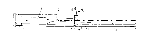
Figure 1 shows as an example a drilling device which is equipped with a casing
tube 1
which drilling device comprises the drilling bit 3 and a percussion hammer 2
behind it, a
rear part 15 of the percussion hammer 2 to which rear part a drill rod 9 is
directed from
the start, in other words the feed part of the drilling in such a way that
pressurized air
flows along the drill rod 9 for the percussion hammer 2 and a rotating
movement comes
along the drill rod for the hammer and for the bit 3, There are support
elements 5,7 at the
intersection of the drill rod 9 and the rear part 15 of the percussion hammer
2 with which
support elements the position of the drill rod 9 and the rear end of the
hammer 2 is
adjusted inside the casing tube 1.
Figure 2 shows a structure of a support element which structure comprises the
first
support element 5, which moves along the casing tube 1 inside the casing tube
1 during
the drilling, which is located inside the casing tube 1 and rotates inside it.
The first
CA 02920074 2016-02-01
WO 2015/018969
PCT/F12014/000018
4
support element 5 comprises wings 13 with the help of which wings it rests on
the casing
tube 1 if the casing tube is used or it rests on the rock hole and slides on
the inner surface
of the hole if the casing tube 1 is not being used. The first support element
5 further
comprises a hole which is located out of centre into which the second
rotatable part 7 is
located the rotation of which part can be locked to the first support element
5 with the
help of a shoulder arrangement 10. Figure 3 shows how the locking occurs with
the help
of the shoulder arrangement 10 when the second support element 7 moves in
axial
direction in relation to the first support element 5. The rotation of the
hammer 2 and the
bit 3 coming through the drill rod 9 occurs through a hole 16 which belongs to
the second
support element 7 through which hole the drill rod 9 is directed to the hammer
2.
In the implementation method of the figures 2 and 3 the drill rod 9 always
rotates one
support element 7 and there are two locking positions for the other support
element 7 to
the first support element 5. With the help of the axial movement of the second
support
element 7 which movement can be created by pulling and/or pushing the drill
rod 9, the
second support element is opened and locked from the locking shoulder 10 in
which case
with the help of the rotation of the drill rod 9 and with the help of the
axial movement
occurring after it the second support element 7 can be locked into the
position according
to the figure 2 in the first support element 5 or into a position which is
turned 180 from
it. If the drill rod is pulled back in order to create the axial movement at
the location of
the support elements and so that the bits/a bit 3 would not be pulled at the
same time,
there can be the needed sliding distance in an axial direction between the
pilot bit and the
broaching bit in the locking position or a corresponding sliding distance
between the pilot
bit and the percussion hammer 2.
In the position according to the figure 2 the hole 16 is located considerably
out of centre
in the casing tube 1. In the position which is turned 180 from it the hole 16
is located at
the centre of the casing tube 1. When the drill rod 9 goes through the hole 16
to the rear
part 15 of the hammer 2, the rear part of the hammer 2 will analogously be
located either
considerably out of centre inside the casing tube 1 or it will be located
exactly at the
centre of the casing tube 1. The drilling in this example is controlled either
when the
position of the hole 16 is moved to the centre of the casing tube 1, in which
case the
drilling proceeds without any controlling action and in which case it should
proceed in a
CA 02920074 2016-02-01
WO 2015/4118969
PCT/F12014/000018
linear way or the drilling is being controlled when the position of the hole
16 is being
moved to be out of centre in relation to the casing tube 1 in which case the
drilling is
being deviated for the amount of the angle a from the linear direction.
5 In the case shown in the figure 2 which is described above the first
support element 5
rotates during the drilling and it cannot be locked to be non-rotatable. When
one wants to
control the drilling direction, the hole 16 must be located in an out of
centre position in
relation to the casing tube 1, such as in the figure 2 and in this position
the second support
element 7 must be locked to the first support element 5. With the help of the
rotation
which is coming from the drill rod 9 bath support elements 5 and 7 rotate and
the hole 16
starts to rotate in a circular orbit and analogously the rear part 15 of the
percussion
hammer 2 starts to rotate in a circular orbit. The drilling device starts to
turn in the desired
direction if the rotation is slowed down with the help of the drill rod 9 or
the impact of the
hammer is boosted when the hole 16 is located in the opposite area in relation
to the
centre line C than in which direction one wants the drilling to be turned (in
the figure 1
the drilling turns upwards).
Control of the drilling requires that one knows the position of the drill head
in relation to
the desired drilling line and that one knows the direction 0¨ 360' in which
the drilling
direction should be turned if there is a need for the turn. In addition to
this one needs to
know when the hole 16 is located in the angle area in relation to the centre
line C of the
drilling in which the rotation of the drill rod 9 must be slowed down or the
impacts must
be boosted. The underground position of the drill head can be found out with
the known
methods by locating the known positioning equipment and a transmitter at the
drill head
and by receiving location data sent by the transmitter with the help of a
receiver which is
located ground surface. The same equipment and the transmitter can also
indicate each
angle position of the hole 16. In this implementation method the percussion
hammer 2 is
located at the drill head. An alternative can also be that the drill rod 9
conveys the impacts
from the starting end in which case there is fior example a drill arm behind
the bit 3 the
rear end of which drill arm is controlled with the help of the support
elements.
In the figure 4 the first support element 5 is shown for which support element
a ring 4 is
welded inside the casing tube 1 which ring stays quite accurately at the
location of the
first support element 5 during the drilling. Ridges 11 which are directed
inwards are
CA 02920074 2016-02-01
WO 2015/018969
PCT/F12014/000018
6
formed on the inner surface of the ring 4 with which ridges the rotation of
the first
support element 5 can be prohibited if the mentioned support element 5 is
moved in an
axial direction so that its wing 13 moves behind the ridge 10. The hole
existing in the first
support element and which is for the second support element 7 is located out
of centre in
relation to the casing tube I. Between the first 5 and the second support
element 7 there is
also a locking to be opened/closed occurring with their mutual axial movement.
Figures 5
and 6 show these lockings 10 and 11. Figure 5 further shows a locking 12 in
which case
by pulling the drill rod 9 first a little bit back the support element 7 will
be organized to
in have a rotational connection with the sleeve part 6 with the help of the
locking 12 which
sleeve part is otherwise adjusted to rotate freely in the inner hole of the
support element 7.
A spring element 8, which is attached to the end of the drill rod 9 and which
allow minor
angle differences between the drill rod 9 and the sleeve part 6 and at the
same time
transmits the rotating movement, is also shown in the figure 5.
Figure 6 shows the lockings 10 and 11 which both can be opened by pulling the
drill rod
9 back and can be locked by pushing and rotating the drill rod 9 till the
shoulders hit each
other for transmitting the rotating power. The lockings 10, 11, 12 can also be
antiparallel
wherein they can be opened by pulling the casing tube 1 backwards.
Controlling of the drilling device of the figures 4 ¨ 6 occurs with the help
of an out of
centre support for example by rotating the casing tube into such angle
position that the
centre of the hole 16 according to the figure 6 and at the same time the
centre of the rear
part 15 of the percussion hammer 2 and the centre of the sleeve part 6 are in
the right, out
of centre angle position regarding the correction of the direction and sleeve
part 6 is in a
freely rotating position inside the support element 7 and the first support
element 5 is
locked to be non-rotatable in relation to the casing tube 1 when its wing part
13 is located
behind the shoulder 11 of the inner surface of the casing tube.
Drilling which is meant to proceed directly is for its part performed by
rotating the second
support element 7 180 from the position of the figure 6 in which case the
sleeve part 6
moves to rotate on the centre line C of the casing tube 1.
In one embodiment the support element of the figures 2 and 6 is attached for
example by
welding it to the casing tube 1 in which case it does not rotate during the
drilling. The
CA 02920074 2016-02-01
WO 2015/018969
PCT/F12014/000018
7
location of the hole 16 which is inside the support element 5 can be orgonized
to be out of
centre by rotating the second support element 7 inside the support element 5.
In this case
the location of the hole 16 can be adjusted into various angles of rotation by
rotating the
casing tube 1 till the hole 16 is located in the desired angle position.
Wheels 18 which are attached with joints 19 and are adjusted to the wing parts
of the first
support element 5 are shown in the figures 7 and 8 which wheels become pressed
onto
the inner surface of the rock hole 17 when the support elements 5' and 7 are
being rotated
clockwise and lock the support element 5' to be non-rotatable but enable the
fact that the
support element 5' can easily proceed in the rock hole. When the support
elements 7, 5'
are being rotated in the direction of the arrow counterclockwise, the wheels
18 stop being
pressed against the surface of the hole 17 and with the help of the drill rod
9 the support
element 5' can be rotated counterclockwise into the desired, new angle
position. Then the
control is adjusted only with the rotation of the drill rod.
With the method according to the invention one can control drillings which are
directed in
various directions and the drilling can be directed also during the drilling
by changing the
rotating speed or the impact energy of the hammer when the rear part of the
drilling
device is deviated from the centre line of the drilling and the impact
direction is in the
desired angle area. The drilling direction is changed by deviating the impact
direction
from the centre line of the drilling device by moving the centre of the rear
part of the drill
head away from the centre line of the drilling device.
There may be changes made for the method at the bit part of the drilling
device. When
the percussion hammer is turned a little bit from the drilling direction, then
the pilot bit
which is attached to the hammer usually turns along with it and there are no
problems
with the impact surface but if there will be an angle difference between
these, the impact
surface may for example be a spherical surface with a large radius. In the
case in which a
ring shoulder, which is meant for transmitting impacts and pulling the casing
tube, is
possibly attached to the pilot bit, this shoulder or its counter surface does
not turn and in
these cases impact surfaces which have a curvilinear form can also be used.
Even though the examples are limited only in the cases where the rear part of
the
percussion hammer or the drill arm is moved only with an out of centre
principle, the
CA 02920074 2016-02-01
WO 2015/018969
PCT/F12014/000018
8
moving of the rear pan can also be performed with many other mechanical ways,
such as
by supporting the mentioned rear part with the help of wedge-shaped pieces and
by
moving the wedges with an axial movement of the drill rod or the casing tube
and/or with
their rotation when the wedges move the rear part into the desired, deviated
position.