Note: Descriptions are shown in the official language in which they were submitted.
CA 02920203 2016-02-05
VEHICLE CARGO CARRIER DEVICE
FIELD OF THE INVENTION
The present invention relates to a cargo carrier device for a vehicle
which includes a cargo frame defining a rack for supporting cargo thereon and
an
operating linkage for displacing the rack relative to the vehicle between a
transport
position above a roof of the vehicle, and a loading position in which the rack
extends
at an upward and forward inclination from a rear end of the rack which is
proximate
ground level at a rear of the vehicle.
BACKGROUND
Various forms of cargo carrier devices are known for supporting
additional cargo on a vehicle. A common type of carrier is a roof mounted rack
which
spans above the roof of the vehicle which is particularly suited for
supporting longer
objects including ladders, boats, or any other desired cargo items to be
transported
which cannot be easily carried on other parts of the vehicle.
Due to the resultant height of a typical roof rack, various attempts have
been made to lower the rack to more easily load cargo items thereon. US Patent
5,609,462 by Reimer discloses one example of a cargo carrier for a vehicle
which is
limited to use with boats and which does not significantly lower the carrier
to allow
access to most of the carrier from ground level. US application publication
no.
2012/0263561 by Li discloses another example of a roof carrier which can be
lowered
to a loading position, but the device is limited to use with box trucks having
a large
roof area to support rollers at the rear of the truck to support the carrier
as it is
displaced between loading and transport positions.
US 7,992,732 by Demiany discloses another example of a cargo
supporting device for a vehicle, but the complex arrangements of parts is
primarily
CA 02920203 2016-02-05
2
directed towards loading a cargo box area of a truck, not providing convenient
loading
access to a roof rack.
SUMMARY OF THE INVENTION
It is an object of the present invention to provide a cargo carrier device
which enables a variety of cargo items to be transported in the manner of a
vehicular
roof rack, but which allows for easier access for loading cargo onto the
carrier device
than conventional racks fixedly supported above the roof of a vehicle.
According to one aspect of the present invention there is provided a
cargo carrier device for supporting cargo relative to a truck having a cargo
box area
with laterally opposed sides extending between a passenger cab at a front of
the
cargo box area and a rear of the cargo box area, the cargo carrier device
comprising:
two mounting assemblies for mounting onto the two laterally opposed
sides of the cargo box area respectively;
a cargo frame for supporting the cargo thereon; and
an operating linkage assembly including a front link assembly and a rear
link assembly operatively connected between the cargo frame and the mounting
assemblies so as to define a four bar linkage in which:
the front link assembly includes two front link members pivotally
coupled between the cargo frame and the mounting assemblies at the laterally
opposing sides of the cargo box area respectively; and
the rear link assembly includes two rear link members pivotally
coupled between the cargo frame and the mounting assemblies at the laterally
opposing sides of the cargo box area respectively;
the four bar linkage being adapted to support the cargo frame to
be movable relative to the cargo box area between a transport position above
the
CA 02920203 2016-02-05
3
cargo box area and a loading position in which at least a portion of the cargo
frame is
more rearward and closer to a ground surface supporting the truck thereon than
in the
transport position.
Preferable the cargo frame defines a cargo supporting platform which is
substantially horizontally oriented above a roof of the passenger cab of the
truck in
the transport position. Preferably the cargo supporting platform is supported
at an
upward and forward inclination in which at least a rear portion of the
platform is
rearward of the truck in the loading position.
The rear end of the rack is preferably adapted to be supported adjacent
to the ground surface in the loading position.
The front link assembly is preferably pivoted through an over-center
position between the loading position and the transport position such that a
pivotal
connection of the front link members to the cargo frame is displaced upwardly
from
the loading position to the over-center position and downwardly from the over-
center
position to the transport position.
Similarly, the rear link assembly is preferably pivoted through an over-
center position between the loading position and the transport position such
that a
pivotal connection of the rear link members to the cargo frame is displaced
upwardly
from the loading position to the over-center position and downwardly from the
over-
center position to the transport position.
Preferably the mounting assemblies are adapted to i) support a pivotal
connection of the rear link members to the mounting assemblies in proximity to
the
rear of the cargo box area, and ii) support a pivotal connection of the front
link
members to the mounting assemblies at a location which is spaced rearwardly of
the
front of the cargo box area and which is spaced forwardly of a pivotal
connection of
CA 02920203 2016-02-05
4
the rear link members to the mounting assemblies.
Preferably a length of the front link members between pivotal
connections to the cargo frame and the mounting assemblies respectively is
greater
than a length of the rear link members between pivotal connections to the
cargo frame
and the mounting assemblies respectively.
The front link members may be stepped in profile such that in the
transport position each front link member defines a first portion extending
forwardly
from a pivotal connection to the mounting assemblies, a second portion
extending
upwardly from the first portion proximate a rear of the passenger cab, and a
third
portion extending forwardly from the second portion over the passenger cab to
a
pivotal connection to the cargo frame.
The rear link members may also be stepped in profile such that in the
loading position each rear link assembly defines a first portion extending
rearwardly
from a pivotal connection to the mounting assemblies and a second portion
extending
downwardly and rearwardly from the first portion to a pivotal connection to
the cargo
frame.
Preferably each front link member i) extends upwardly and forwardly
between a pivotal connection to the mounting assemblies and a pivotal
connection to
the cargo frame in the transport position and ii) extends upwardly and
rearwardly
between the pivotal connection to the mounting assemblies and the pivotal
connection
to the cargo frame in the loading position.
Preferably each rear link assembly i) extends upwardly and forwardly
between a pivotal connection to the mounting assemblies and a pivotal
connection to
the cargo frame in the transport position and ii) extends downwardly and
rearwardly
between the pivotal connection to the mounting assembly and the pivotal
connection
CA 02920203 2016-02-05
to the cargo frame in the loading position.
When the cargo frame comprises i) two side portions, each side portion
pivotally coupling one of the front link members and one of the rear link
members
thereon, and ii) a cargo supporting crossbar spanning between the two side
portions,
5 preferably the cargo supporting crossbar is adapted to be supported in
the transport
position directly above the cargo box area and in the loading position spaced
rearward of the cargo box area, lower in elevation than the transport
position.
A winch may be supported on the cargo supporting crossbar.
When the two side portions define a cargo supporting platform which is
substantially horizontally oriented in the transport position, preferably the
cargo
supporting crossbar is spaced above the two side portions in the transport
position.
The cargo frame may further comprise two pivot arms pivotally coupled
to the two side portions of the cargo frame respectively, the two pivot arms
being
joined to opposing ends of the cargo supporting crossbar such that the cargo
supporting crossbar is supported for pivotal movement between a working
orientation
spaced above the two side portions in the transport position of the cargo
frame and a
stored orientation lying in a common plane with the two side portions of the
cargo
frame respectively.
The pivot arms may support the cargo supporting crossbar for pivotal
movement about a common pivot axis relative to the cargo frame in two opposing
directions from the working orientation to opposed first and second storage
conditions
respectively, in which the cargo supporting crossbar is in a common plane with
the
two side portions spaced forwardly of the common pivot axis in the first
storage
condition, and in which the cargo supporting crossbar is in said common plane
with
the two side portions spaced rearwardly of the common pivot axis in the second
CA 02920203 2016-02-05
6
storage condition.
According to a second aspect of the present invention there is provided
a cargo carrier device for supporting cargo relative to a truck having a cargo
box area
with laterally opposed sides extending between a passenger cab at a front of
the
cargo box area and a rear of the cargo box area, the cargo carrier device
comprising:
two mounting assemblies for mounting onto the two laterally opposed
sides of the cargo box area respectively;
a cargo frame comprising two side portions and a cargo supporting
crossbar spanning between the two side portions for suspending the cargo
therefrom;
and
an operating linkage assembly including a front link assembly and a rear
link assembly operatively connected between the cargo frame and the mounting
assemblies so as to define a four bar linkage in which:
the front link assembly includes two front link members pivotally
coupled between the mounting assemblies and the two side portions of the cargo
frame at the laterally opposing sides of the cargo box area respectively; and
the rear link assembly includes two rear link members pivotally
coupled between the mounting assemblies and the two side portions of the cargo
frame at the laterally opposing sides of the cargo box area respectively;
the four bar linkage being adapted to support the cargo frame to
be movable relative to the cargo box area between a transport position in
which the
cargo supporting crossbar is supported directly above the cargo box area and a
loading position in which the cargo supporting crossbar is spaced rearward of
the
cargo box area, lower in elevation than the transport position.
According to another aspect of the invention there is provided a cargo
CA 02920203 2016-02-05
7
carrier device for supporting cargo relative to a vehicle, the device
comprising:
a rack for supporting the cargo thereon; and
an operating linkage assembly arranged to be operatively connected
between the rack and the vehicle to define a four bar linkage such that the
rack is
pivotally movable between a transport position above a roof of the vehicle and
a
loading position in which the rack is more upright in orientation and closer
to the
ground than in the transport position.
The rack is designed to lift and pivot the load upwardly and forwardly
over the vehicle, specifically to clear objects such a toppers, quad runners,
outboard
motors and anything else that may be in the box. The unique design and
geometry is
set up so that the rack goes up, then back and finally down on the back side.
It gets
very close to the ground at the bottom while the top stays at an angle so that
any
potential load can be leaned against the rack, fastened on and then via power
source,
(hydraulic, linear actuators, or winches and cables, or chains) lifted up and
onto the
truck, in most cases ready to go.
Preferably the operating linkage assembly comprises a rear link
assembly arranged to be pivotally coupled between the rack and a respective
first
portion of the vehicle in proximity to a rear end of the vehicle and a front
link assembly
arranged to be pivotally coupled between the rack at a location spaced
forwardly of
the rear link and a respective second portion of the vehicle spaced forwardly
from the
first portion of the vehicle.
Preferably the front link assembly and the rear link assembly each
comprises a pair of link members supported at laterally opposing sides of the
rack for
pivotal movement relative to the rack about a common lateral pivot axis of the
link
assembly.
CA 02920203 2016-02-05
8
The device preferably also includes a linear actuator, for example an
electric or hydraulic actuator, which is arranged to be operatively connected
between
the vehicle and the operating linkage assembly so as to be arranged to
displace the
operating linkage assembly between the transport position and the loading
position as
the linear actuator is extended and retracted.
Various embodiments of the invention will now be described in
conjunction with the accompanying drawings in which:
BRIEF DESCRIPTION OF THE DRAWINGS
Figure 1 is a side elevational view of the cargo carrier device according
to a first embodiment supported on a vehicle in a transport position of the
cargo
frame;
Figure 2 is a side elevational view of the cargo carrier device according
to the first embodiment supported on the vehicle in an intermediate position
of the
cargo frame between the transport position and a loading position;
Figure 3 is a side elevational view of the cargo carrier device according
to the first embodiment supported on the vehicle in the loading position of
the cargo
frame;
Figure 4 is a rear elevational view of the cargo carrier device according
to the first embodiment supported on the vehicle in the transport position;
Figure 5 is a perspective view of a second embodiment of the cargo
carrier device;
Figure 6 is a side elevational view of the cargo carrier device according
to the second embodiment in the transport position;
Figure 7 is a side elevational view of the cargo carrier device according
to the second embodiment in the intermediate position;
CA 02920203 2016-02-05
9
Figure 8 is a side elevational view of the cargo carrier device according
to the second embodiment in the loading position;
Figure 9 is a vertical cross section view oriented in the longitudinal
direction of the cargo supporting crossbar of the second embodiment in the
first
storage condition;
Figure 10 is the vertical cross section view of Figure 9 in the working
condition of the cargo supporting crossbar; and
Figure 11 is the vertical cross section view of Figure 9 in the second
storage condition of the cargo supporting crossbar.
In the drawings like characters of reference indicate corresponding parts
in the different figures.
DETAILED DESCRIPTION
Referring to the accompanying figures there is illustrated a cargo carrier
device generally indicated by reference numeral 10. The device 10 is
particularly
suited for carrying various cargo items 12 relative to a vehicle 14.
In each of the illustrated embodiments, the vehicle comprises a pickup
truck. More particularly the truck 14 includes an operator/passenger cab 16
for
supporting passengers therein in proximity to the forward end of the vehicle
and a
cargo box area 18 at the rear of the vehicle. The cargo box area includes two
side
walls 20 extending in the longitudinal direction of the vehicle at laterally
opposing
sides of the cargo box area between the rear wall of the operator cab 16 at
the front of
the cargo box area and a gate at the rear end of the cargo box area.
The cargo box area may remain open at the top end thereof, or be
enclosed by a tonneau cover, or alternatively the enclosed by a raised box
cover is
shown in broken line in Figures 1 and 3. A typical raised box cover includes
side
CA 02920203 2016-02-05
portions which rest on the side walls of the cargo box area to extend upwardly
therefrom to a roof portion fully spanning over the cargo box area at a
location spaced
above the side walls.
According to the first illustrated embodiment of Figures 1 through 4, the
5 cargo item comprises a boat. According to the second illustrated embodiment
of
Figures 5 through 11, the cargo item comprises a cargo object suspended from a
cable.
Although various embodiments of the cargo carrier device are shown in
the accompanying figures, the common features between the two embodiments will
10 first be described.
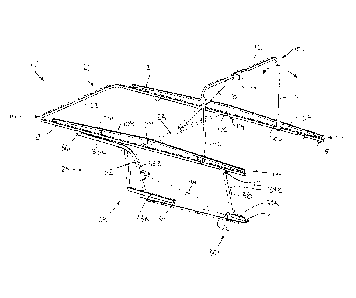
The device 10 generally includes a cargo frame 22 defining a rack
formed of frame members lying generally in a flat plane having an upper
surface
forming a load supporting platform suitable for supporting the cargo thereon.
For
example the frame members of the rack may include two side rails 21 spanning
longitudinally along laterally opposing sides of the rack and which are
connected to
one another by laterally extending crossbars 23 at longitudinally spaced
positions.
The frame of the rack may remain open, or a load supporting panel may span the
top
side of the frame to assist in supporting smaller cargo items thereon. The
rack may
further include side walls, posts, brackets or other protruding elements which
may be
useful in securing cargo to the upper side of the planar frame primarily
defining the
rack 22.
The device 10 also includes an operating linkage assembly 24 for being
coupled between the vehicle and the rack such that the rack is supported for
movement between a transport position supported above the roof of the vehicle
in a
horizontal orientation as shown in Figure 1 and a loading position in which
the rack is
CA 02920203 2016-02-05
11
more upright in orientation and closer to the ground towards a rear end of the
vehicle
so as to extend at an upward and forward inclination from a rear end of the
rack
substantially at ground level in the transport position as shown in Figure 3.
The operating linkage assembly 24 includes two mounting assemblies in
the form of side rails 26 which are arranged to be secured along the top side
of the
two side walls 20 of the cargo box area of the truck respectively. Each side
rail may
comprise a flange portion with suitable mounting apertures therein which is
suited for
being fastened between the top end of the side walls of the truck box and a
box cover
for enclosing the truck box which is supported thereabove.
The operating linkage assembly 24 further includes a front link assembly
28 pivotally coupled between the side rails 26 and the rack 22 towards a front
end
thereof and a rear link assembly 30 pivotally coupled between the side rails
26 and
the rack 22 towards a rear end thereof.
The front link assembly 28 comprises two front link members 32 which
are supported at respective laterally opposing sides of the cargo box area and
the
rack by being pivotally connected to the two side rails at respective lower
pivot
connections 34 defining a first common lateral axis and by being pivotally
connected
to opposing sides of the rack at respective upper pivot connections 36
defining a
second common lateral axis.
The lower pivot connections 34 of the front link assembly are located at
the top side of the side walls of the cargo box area closer to the front end
of the cargo
box than the rear end thereof while remaining space rearwardly from the front
end of
the box area. The upper pivot connections 36 are in proximity to the front end
of the
rack so as to be positioned forwardly of the operator cab of the vehicle in
the transport
position. More particularly, each front link member 32 extends upwardly and
forwardly
CA 02920203 2016-02-05
12
from the lower pivot connection to the upper pivot connection in the transport
position.
As the rack is displaced to the loading position from the transport
position, the upper pivot connections of the front link members are displaced
upwardly
and rearwardly to an over centre position followed by downward and rearward
movement to the final loading position in which the front link members extend
upwardly and rearwardly from the lower pivot connections to the upper pivot
connections thereof.
Each front link member 32 is stepped in profile such that it includes a
first portion 33A which extends horizontally forward from the lower pivot
connection in
the transport position, a second portion 33B which extends vertically upward
from the
forward end of the first portion alongside the rear of the operator cab in the
transport
position, and a third portion 33C which extends horizontally forward over top
of the
operator cab from the top end of the second portion to the upper pivot
connection at
the forward end thereof in the transport position.
The rear link assembly 30 comprises two rear link members 38 which
are supported at respective laterally opposing sides of the cargo box area and
the
rack by being pivotally connected to the two side rails at respective lower
pivot
connections 40 defining another common lateral axis and by being pivotally
connected to opposing sides of the rack at respective upper pivot connections
42
defining a further common lateral axis.
The lower pivot connections 40 of the rear links are situated at the top
side of the side walls of the cargo box area in proximity to the rear ends of
the side
walls at the rear of the cargo box area. The upper pivot connections 42 are
located on
the rack to be closer to the rear end of the rack than the forward end thereof
while
remaining spaced forwardly from the rear end in the transport position. The
upper
CA 02920203 2016-02-05
13
pivot connections 42 are thus located upwardly and forwardly relative to the
lower
pivot connections of the rear link members in the transport position.
As the rack is displaced to the loading position from the transport
position the upper pivot connections of the rear link members are initially
displaced
upwardly and rearwardly to an over centre position, followed by downward and
rearward movement from the over centre position to the final loading position
in which
the rear link members are oriented to extend downwardly and rearwardly from
the
lower pivot connections to the upper pivot connections.
Each rear link member is also stepped in profile such that it defines a
first portion 39A which extends horizontally forward from the lower pivot
connection in
the transport position but which extends horizontally rearward from the lower
pivot
connection in the loading position, and a second portion 39B which is inclined
upwardly and forwardly from the front end of the first portion in the
transport position
but which extends downwardly and rearwardly from the first portion to the
upper pivot
connection parallel to the plane of the rack along the bottom side thereof in
the
loading position.
The front links of the front link assembly, the rear links of the rear link
assembly, the side rails 26, and the frame of the rack 22, together with the
upper and
lower pivot connections therebetween effectively define a four bar linkage
configuration which controls the movement of the rack relative to the vehicle
between
the loading and transport positions.
The device 10 further includes two linear actuators 44 supported at
laterally opposing sides of the vehicle. Each linear actuator is pivotally
coupled at a
first end to a respective one of the side rails 26 towards the rear end
thereof at a
location forwardly of the lower pivot connection of the corresponding rear
link member
CA 02920203 2016-02-05
14
and is pivotally coupled at a second end to a respective one of the front link
members
at an intermediate location along the second portion 33B thereof. Extending
the two
linear actuators 44 in unison causes the operating linkage assembly to
displace the
rack to the transport position shown in Figure 1. Alternatively, retracting
the two linear
actuators in unison causes the operating linkage to displace the rack to the
loading
position shown in Figure 3.
Typically the linear actuators 44 each comprise a hydraulic piston
cylinder arrangement or an electrically controlled actuator which allows
precise
operator controlled to extend and retract the length thereof.
In yet further embodiments the linear actuators 44 may be replaced with
various types of actuating mechanisms including winches, cables, pulleys
and/or
gears for example.
In use, the device 10 is mounted on a vehicle by securing the two side
rails 26 thereof along the top sides of the two side walls of a cargo box area
of a
pickup truck. The actuators are used to lower the rack into the loading
position in
which the upper supporting surface defining the plane of the rack lies at an
upward
and forward inclination with the rear end thereof substantially at ground
level towards
the rear of the vehicle. A cargo item can be leaned against the upper
supporting
surface of the rack and secured in place using straps and the like for
example. In the
example of a boat, an open frame of the rack allows protruding element
including
seats or a motor and the like to protrude through the plane of the rack. The
actuators
can then be operated to raise the rack by pivoting the link members so that
the rack is
displaced upwardly and forwardly through an over centre position towards the
transport position shown in Figure 1. The front and rear links pivoting over
centre
ensure clearance is provided for the rack to extend up and over a cargo box
cover for
CA 02920203 2016-02-05
example without interference therebetween. Once in the transport position, the
rack
can be secured by various means, including use of locking pins at one or more
locations along the link members, use of securing straps, or locking of the
actuators
44 for example. To unload the cargo item, the reverse operation is performed
by
5 unlocking the rack from the transport position, pivoting the rack to the
loading position,
and releasing the cargo item from the rack.
According to the first embodiment of Figures 1 through 4, the cargo
frame is a planar frame suited primarily for use as a cargo rack.
According to the second embodiment of Figures 5 through 11, the cargo
10 frame includes a main frame portion 100 and a pivoting frame portion 102
which is
pivotal relative to the main frame portion 100 between a working condition
shown in
Figures 5, 6, 7, 8 and 10, a first storage condition shown in Figure 9, and a
second
storage condition shown in Figure 11.
The main frame portion 100 of the cargo frame includes the two side
15 rails 21 extending longitudinally the full length of the main frame
portion at laterally
opposing sides relative to one another. The two side rails 21 define two
laterally
opposed side portions of the cargo frame upon which the front and rear link
members
are pivotally connected as described above. The two side rails are joined to
one
another at respective front ends by a forward crossbar 23, and are joined to
one
another at an intermediate, central location in the longitudinal direction by
an
intermediate crossbar 23. An area between the two side rails rearward of the
intermediate crossbar 23 remains open and unobstructed such that each side
rail 21
terminates at a free rear end. The crossbars 23 and the side rails 21 lie in a
common
plane defining the planar platform surface of the cargo frame upon which cargo
can
be supported.
CA 02920203 2016-02-05
16
A railing frame 104 is mounted to each of the two side rails 21 to
protrude upwardly from the planar frame structure defined by the side rails 21
along
substantially the full length of the main frame portion 100 in the transport
position.
Each railing frame 104 comprises a plurality of posts 106 protruding up from
the
respective side rail at longitudinally spaced apart positions and a top bar
108
connected across the top ends of the posts 106 to extend in the longitudinal
direction
above the respective side rail 21. The railing frames serve to assist in
containing
cargo supported on the platform structure defined by the crossbars 23.
The pivoting frame portion 102 generally includes two pivot arms 110
which are pivotally supported at respective first ends of the pivot arms on
the two side
rails 21 respectively at an intermediate location which is approximately
longitudinally
centred between the intermediate crossbar 23 and the free rear ends of the
side rails
21. The pivot location of the pivot arms is thus positioned to be spaced
rearwardly
from the intermediate crossbar 23 yet spaced forwardly of the rear ends of the
side
rails defining the rear end of the main frame portion 100.
The two pivot arms 110 of the pivoting frame structure are joined to one
another at the opposing second ends by a cargo supporting crossbar 112
connected
in fixed relation to the two pivot arms such that the two pivot arms and the
cargo
supporting crossbar 112 define a generally U shaped frame structure pivoted
together
relative to the main frame portion 100. The cargo supporting crossbar 112 thus
spans laterally a full width of the cargo frame between the two laterally
opposed side
portions of the cargo frame.
The length of the pivot arms between the first and second ends thereof
is near to or slightly less than a longitudinal distance between the pivotal
connection
of the pivot arms to the side rails and the mounting location of the
intermediate
CA 02920203 2016-02-05
17
crossbar 23 to the side rails. In this manner the pivoting frame structure can
be
pivoted forwardly into a first stored position in which the pivot arms extend
forwardly
from the first ends to the second ends thereof and the cargo supporting
crossbar is
adjacent to the intermediate crossbar 23 with the pivoting frame portion 102
lying
substantially in a common plane with the side rails 21.
Two stop members 114 protrude inwardly from the bottom sides of the
two side rails 21 at a location in proximity to but spaced rearwardly from the
intermediate crossbar such that the pivoting frame portion 102 can be engaged
upon
the stop members in the first stored position to prevent further downward
pivoting of
the pivot frame portion 102 beyond the first stored position.
The pivoting frame portion 102 can be pivoted upwardly and rearwardly
from the first stored position to a working position in which the pivot arms
extend
generally perpendicularly upwardly from the two side rails respectively such
that the
cargo supporting crossbar is spaced above the platform of the main frame
portion 100
by a distance which is greater than the height of the operating linkage 24 in
the
transport position. The cargo supporting crossbar 112 is located relative to
the main
frame portion such that the crossbar is located at an intermediate location
spaced
from both front and rear ends of the cargo box area, directly above the cargo
box area
in the transport position.
A winch 116 is mounted at a laterally centred location on the cargo
supporting crossbar having a drum with a cable wound thereon from which the
cargo
item can be suspended as the cargo frame is displaced between transport and
loading positions.
To assist in retaining the pivoting frame structure in the working position,
an additional brace arm 118 can be selectively secured using releasable pin
CA 02920203 2016-02-05
18
connections to the intermediate crossbar 23 and the cargo supporting crossbar
112
respectively. More particularly, the brace arm 118 is adapted for a removable
pinned
connection at a forward end of the brace arm to a laterally centred location
on the
intermediate crossbar 23. The brace arm extends upwardly and rearwardly from
the
intermediate crossbar to a removable pinned connection at a rearward end of
the
brace arm at a laterally centred location on the cargo supporting crossbar
112.
Removing the pin connections allows the brace arm to be separated from the
cargo
frame to permit free pivoting of the pivoting frame portion 102 relative to
the main
frame portion 100.
The crossbar 112 of the pivoting frame structure is pivoted upwardly and
rearwardly from the first stored position to the working position, and can
continue to
pivot beyond the working position downwardly and rearwardly to a second stored
position shown in figure 11. In the second stored position the pivot arms
extend
rearwardly from the first ends to the second ends thereof in a common plane
with the
side rails such that the cargo supporting crossbar 112 is spaced rearwardly
relative to
the rear ends of the side rails 21 while remaining in a common plane with the
side
rails.
Additional stop members 115 protrude inwardly from the opposing side
rails in proximity to the rear ends of the side rails upon which the pivot
arms of the
pivoting frame structure are engaged in the second stored position to prevent
further
downward pivoting of the pivoting frame portion 102 beyond the second stored
position.
Locking pins can be received through cooperating apertures in the pivot
arms and the side rails 21 to selectively retain the pivoting frame portion
102 in fixed
relation to the main frame portion 100 in each of the first and second stored
positions.
CA 02920203 2016-02-05
19
Locating the pivoting frame portion in the first stored position is
particularly suited for maintaining an open unobstructed access to the cargo
box area
of the truck.
Alternatively, locating the pivot frame portion 102 in the second stored
position is particularly suited for use of the cargo supporting crossbar 112
as an
additional platform defining structure of the rack when using the cargo frame
to
support elongated cargo items on the planar platform structure of the cargo
frame.
Supporting the pivoting frame portion 102 in the working position of
figure 5 is particularly suited for suspending cargo items from the cargo
supporting
crossbar 112 using a cable. In the working position of the pivoting frame
portion 102,
the cargo supporting crossbar 112 is typically positioned at a location spaced
rearwardly from the truck at a lower elevation closer to a ground surface
supporting
the truck thereon than in the transport position. Accordingly the cargo item
on the
ground rearward of the truck box can be initially suspended from the cargo
supporting
crossbar. Subsequent displacement of the cargo frame from the loading position
to
the transport position may then sufficient to lift the cargo item suspended
from the
crossbar 112 upwardly and forwardly into an intermediate over-centre position,
followed by continued displacement forwardly and downwardly into the cargo box
area as the cargo frame reaches the transport position. The winch may also be
used
to lift the cargo item relative to the cargo supporting crossbar by winding
the cable
suspending the cargo item onto the winch.
Since various modifications can be made in my invention as herein
above described, it is intended that all matter contained in the accompanying
specification shall be interpreted as illustrative only and not in a limiting
sense.