Note: Descriptions are shown in the official language in which they were submitted.
CA 02920438 2016-02-09
1
TITLE: SCREEN PANEL LOCKING SYSTEM
FIELD OF THE INVENTION
The present invention relates generally to apparatus for screening,
separating or grading materials, and is principally for use in the mining
industry. The present invention is particularly directed to arrangements for
fixing screen panels to the support frame of a vibratory screening machine
and to the screen panels themselves. The system and panels are applicable
for screening, separating and grading ores and other materials, and it will be
convenient to hereinafter describe the invention in relation to that use. It
is to
be appreciated, however, that the invention is not limited to such apparatus
and use.
BACKGROUND OF INVENTION
A reference herein to prior art is not to be taken as an admission
that the prior art was known or that it was part of the common general
knowledge as at the priority date of any of the claims.
Screening apparatus of the type with which the invention is
concerned is generally used for screening, grading, or separating materials
such as ores and comprises an array of screen panels which are removably
fixed to a frame to provide a continuous screen deck. The material to be
screened is fed onto the deck at one end and the apparatus is vibrated so
that the material moves over and through its screening surface. The vibration
forces are significant.
The screen panels in a screen deck are usually subject to wear,
due to the abrasiveness of the mining materials typically being screened, and
thus the screens require periodical replacement. This presents a difficulty
with the attachment of the panels to the deck frame, as the attachment must
be secure and robust and easily made, but it should also be releasable in a
manner that is quick and easy. Applicant has developed several different
CA 02920438 2016-02-09
2
forms of screen panel attachments, examples of which can be found in
Australian patent no. 2012201297 and Australian patent no. 2012208984.
In addition to the need for screen panels to be easily attachable
and releasable to and from a screen deck frame, screen panels should also
be firmly secured in place on the deck and the screen array should not
present gaps for passage of screening product or media other than through
the openings formed in the screens themselves. If gaps do exist, then
incorrect grade screening product can pass through the deck, or the
screening product can become embedded between components of the
screening deck and can cause wear to the screen panels or the screen deck
frame. This can result in the need to clean parts of the vibratory machine or
replace parts, either of which results in downtime of the vibratory machine.
Screen decks are therefore formed with either the side edges of
adjacent screen panels abutting, or with cover strips employed between
adjacent screen panels to overlie any gaps between the adjacent side edges.
A screen deck can thus usually be formed without any gaps being present.
However, if there is any movement of the screen panels during operation of
the vibratory machine, then gaps can result. One form of movement that can
create gaps is movement of screen panels in the direction of travel of the
screening product over the screening deck. This type of movement is more
likely to occur in so-called multi-slope or "banana" screening decks, in which
the lead or initial section of deck is inclined or curved to increase the
speed
of the screening product across the initial section of the screening deck.
Such screening decks can also provide other benefits or effects such as to
promote water shedding from the screening product. For at least these
reasons, the use of multi-slope screening decks is preferred in many
installations. However, in the inclined or curved section of the screening
deck, the screening product moves at high speed and the forces associated
with that movement tends to push the screen panels over which the
screening product travels. If the screen panels move under that load, gaps
between panels can arise.
CA 02920438 2016-02-09
3
The present invention seeks to provide an arrangement in which
movement of screen panels in the manner described above is minimised or
eliminated. The elimination of movement is intended once the screen panels
have been finally positioned or installed, such that in some forms of the
invention, movement of the screen panels is allowed during installation, but
is
prevented once the panels have been fully installed ready for operation of the
vibratory machine.
SUMMARY OF INVENTION
According to the present invention there is provided a screening
apparatus, including:
a plurality of spaced apart, substantially parallel elongate beams,
a plurality of screen panels mounted to the beams to form a broad
screening surface, each of the panels having a generally square or
rectangular shape defining a first pair of substantially parallel edges and a
second pair of substantially parallel edges, and the panels being mounted
adjacent to each other so that facing side edges of adjacent panels are in
close facing relationship, each panel being mounted to a pair of beams to
bridge between two adjacent beams,
the panels being mounted to the beams by elongate fixing
members that extend in the longitudinal direction of the beams and that
engage the first pair of side edges of the panels,
the fixing members having a pair of upstanding, generally
longitudinal rails that are generally parallel and that are spaced apart to
define a longitudinal gap between them, the panels being mounted to the
beams by cooperation between the first pair of side edges of each panel with
a rail of a fixing member,
the first pair of side edges of each panel including a longitudinal
overhang that overlies an upper end of a rail and the overhang entering the
gap between the rails,
each of the rails of each fixing member and the overhang of each
panel being interrupted to form gaps that are aligned and within which a
CA 02920438 2016-02-09
,
,
4
locking member is disposed to locate the panel relative to the fixing rail
against movement of the panel along the fixing rail.
A screening apparatus as above described advantageously
secures the screen panels in place on the fixing members against movement
longitudinally of the fixing members by the use of the locking members. The
locking members bear against the inside or facing surfaces of the locating
gaps and because the locating gaps include gaps formed in both the screen
panels and the fixing members, engagement of the locking members with
both the screen panels and the fixing members locks the screen panels
relative to the fixing members. This reduces the likelihood, or even ensures
that gaps between adjacent screen panels do not form by longitudinal
movement of the screen panels, such as due to the screening product
pushing the screen panels during travel over the screen deck.
A further advantage of the present invention is that the aligned
gaps formed in the overhang of each panel and the fixing members form
lifting positions for lifting a screen panel from a fixing rail for the
purpose of
removing the screen panel for replacement. A suitable tool can be used for
this purpose and in most cases, a screwdriver or like tool can be used to
lever a screen panel from a fixing member through the aligned gaps. Before
a screen panel can be removed, the locking member that is inserted into the
aligned gaps must be removed, but the same tool that is used to remove a
screen panel can be used to lever a locking member out of the aligned gaps.
Thus, removal of screen panels for replacement purposes can be quick and
easy and requires no particular skill or specialised tools.
While the defined requirement is that adjacent panels are mounted
so that facing side edges of adjacent panels are in close facing relationship,
it
is intended that adjacent panels are mounted so that facing side edges are in
touching engagement along those facing side edges so that a seal is created
between facing side edges against passage of screening product past facing
side edges. However, applicant recognises that where adjacent panels are
CA 02920438 2016-02-09
not properly aligned, small gaps might exist between facing side edges and
therefore the requirement for mounting the panels to be in close facing
relationship is intended to cover both arrangements in which facing side
edges are in touching engagement as well as where small gaps exist
5 between facing side edges.
The overhangs of two adjacent screen panels can engage in order
to seal the junction or engagement between those two panels and in some
forms of the invention, each overhang can present an engagement surface
for engagement with a facing engagement surface of the overhang of an
adjacent screen panel. The engagement between the facing engagement
surfaces can be within the gap between adjacent rails of a fixing member, or
can be external to that gap, i.e. above the gap or laterally spaced from the
gap, or the engagement between the facing engagement surfaces can be a
combination of within the gap as well as external to that gap.
The preferred arrangement is that the engagement surfaces
engage at least within the gap between adjacent rails but preferably also
above the gap such as to the upper or screening surface of the screening
apparatus. The preference is that the engagement surfaces be substantially
flat surfaces and the further preference is that those surfaces extend
substantially perpendicularly to the plane of the screening surface.
In the above arrangement, the screen panels can have an
identical shape, which has advantages in production and storage of panels
(reducing the number of different panels needing to be stored), while
installation is facilitated given that the single form of panel can be used
across a complete screening deck.
The rails of the fixing members can be made from any suitable
materials, such as plastics or polymers, but in some forms of the invention, a
polyurethane material is employed. This means that the rails can be flexible
and while that can assist installation of screen panels into the screening
apparatus, once the screen panels are installed, the preference is that the
CA 02920438 2016-02-09
6
rails do not move or flex. Accordingly, by arranging for engagement between
the overhangs of adjacent screen panels, the rails of the fixing members can
be fixed in place via their engagement or cooperation with the side edges of
the screen panels against flexing or tipping movement.
In one particular form of the invention, the cooperation between
the first pair of side edges of each panel and a rail of a fixing member
includes a projection that extends either from one of the side edges of each
panel or the rail of a fixing member, and a groove which is formed in the
other of the side edges of each panel and the rail, within which the
projection
is received. The projection can extend generally in a plane that is parallel
to
the plane of the screening surface, and the projection and groove can be
located between a beam of the screening apparatus to which the screen
panels are mounted and the overhang of the screen panel. By this
arrangement, once the projection is received within the groove, the screen
panel is located relative to the fixing member against lifting away from each
of the fixing member and the beam to which the fixing member is mounted.
In order to form the groove and projection arrangement discussed
above, the rails of the fixing members can extend from a base and can
include an upright web section and a head that is formed at an upper end of
the web section. In this arrangement, a groove can be formed between the
base and the head for receipt of a projection which extends from the side
edge of each panel. The base and the head can form facing surfaces of the
groove. The projection can be a longitudinal projection, or a series of
disconnected projections that extend in a longitudinal path or direction. The
projection can be interrupted in the same manner as the overhang and the
rails of the fixing member to form a gap for receipt of a locking member,
although in alternative forms of the invention, the projection can be
continuous without interruption, with the gap for the locking member formed
above it.
Where the rails include a web section and a head, the overhang
can extend over the head and into the gap between adjacent rails. To
CA 02920438 2016-02-09
7
facilitate insertion of a portion of the overhang into the gap, that portion
of the
overhang that does extend into the gap can have an inclined face that can be
placed or pushed into engagement with the head of the rail and thereafter will
ride along the inclined face as it is pushed further into the gap. The
inclined
face can extend for the full portion of the overhang that extends into the
gap,
or for a section of the portion that extends into the gap.
In arrangements in which facing surfaces of adjacent overhangs
engage, the engaging faces can seal against passage of screening product
past the junction of the engaged faces. This differs from some prior art
arrangements in which facing surfaces of adjacent overhangs do not engage
and which therefore include "locking strips", that overlie the junction
between
facing edges of adjacent screen panels to seal the junction. The
arrangement of the present invention is particularly appropriate where the
screening product is a "dry" screening product such as iron ore, bauxite or
copper. These types of products are less able to pass between engaged
faces and the absence of a locking strip means that the cost of installation
of
the screening apparatus is reduced, as is the complexity of installation.
A single locking member can be employed to locate facing first
edges of a pair of adjacent screen panels against movement along the fixing
rail. Thus, the overhang of each of the first pair of edges of each screen
panel can include a single gap to accommodate insertion of a single locking
member. Alternatively, the overhang of each of the first pair of edges of each
screen panel can include two gaps that are spaced apart to form two locating
gaps between adjacent screen panels and the rails of the fixing members can
include corresponding gaps for alignment with the locating gaps of the two
overhangs. In this arrangement, the screen panels can be located relative to
the fixing rail against movement along the rail by a pair of locking members
inserted into two separate locating gaps. In this arrangement, the gaps can
be formed towards opposite ends of the first edges of each screen panel so
that the locating members locate the screen panels towards the corners
thereof.
CA 02920438 2016-02-09
8
In still alternative arrangements, more than two locating members
can be employed along the first edges of a screen panel, although it is
expected that one or two locating members will properly locate a screen
panel. The preference is for two locating members as discussed above
being located towards corners of each screen panel.
The locking members can be located in any suitable manner within
the locating gaps to locate the screen panels relative to the fixing members.
To resist release of the locking members from within the locating gaps, the
locking members could be threaded, with the walls of the aligned gaps
including threaded portions. Alternatively, the locking members could extend
through and into the beam and be fixed by a locking nut or clip or the like
beneath the beam.
However, the preferred arrangement at this stage to resist release
of the locking members from within the locating gaps is for the locking
members to each include at least a pair of projections that project from
opposite sides of the locking member for engaging under a projection formed
in the facing first edges of adjacent screen panels or in facing surfaces of
the
fixing members. The preference is for the projections to be formed in the
facing first edges of adjacent screen panels.
Where projections extend from the facing edges of the screen
panels, the projections of the locking member will underlie the projections
extending from the facing edges of the screen panels and thus hold the
locking members in place against upward release out of the locating gaps.
This arrangement is easy to assemble, given that the locking members can
simply be pushed into the aligned locating gaps and once the locking
member projections have reached a position of underlying the edge
projections, release of the locking members from the aligned locating gaps is
not possible without an external force being applied, such as by a
screwdriver or like tool. Such an arrangement can withstand the load placed
on the screening deck by a vibratory machine and is extremely simple from
the point of view of manufacturing the locking members, as well as from the
CA 02920438 2016-02-09
9
point of view of installing them as described above. Moreover, whether
locking members are made from polyurethane or like material, a screwdriver
or like tool can be inserted between side edges of the aligned gaps and the
locking member to lever at the locking member out of the aligned gaps.
The projections that extend from opposite sides of the locking
member can extend in a direction which is generally perpendicular to the
longitudinal extent of the fixing members, or alternatively, generally
parallel to
the longitudinal extent of the fixing members, or in both directions. For
example, the locking members can include four projections. Where the
locking members are square, the four projections can each extend from a
face of the locking member.
Moreover, the projections of the facing first edges of adjacent
screen panels can be formed in a portion or portions of the overhang of each
of the screen panels within which the locating gap is formed. That is, edges
of the overhang that define the gap formed in the overhang can form the/or
part of a projection under which a locking member projection can be located.
This means additional and separate projections are not required. Again, this
arrangement simplifies the structure of the screening apparatus by employing
portions of the overhang to form the projections under which the locking
member projections are seated.
The locking member can be of any suitable shape, including
square, rectangular, circular or oval. However, a preferred shape of a locking
member is square or rectangular and in that form of locking member, two or
four projections can be included. The
preference is to include four
projections, being one projection extending from each wall of the locking
member. In this preferred form, the walls of the overhangs of the screen
panels that form the gaps for receipt of a locking member can form or
constitute projections for cooperation with the projections of the locking
members and the projections of the overhangs can be formed continuously
by the entire wall, or by a portion of the wall. The projections of the walls
of
CA 02920438 2016-02-09
the overhangs can, for example, be formed by the underneath surfaces of the
walls, instead of having actual projections that extend from the walls.
A screening apparatus according to the present invention can also
include a side clamp, which is positioned against each of opposing side walls
5 of a screening apparatus and which has a bottom surface that bears
against
the upper surface of edges of screen panels that face the side walls, to hold
the edges of screen panels that face the side walls against lifting. The side
clamp extends longitudinally of the screening apparatus for substantially the
extent of the screen panels and cooperates with a clamping arrangement
10 which engages an upper edge of the side clamp to push or press the side
clamp downwards. The side clamp also includes a spacing arrangement
along a bottom edge thereof for taking up space between the side wall and
the facing edge of the adjacent screen panels. In this respect, once a
screening deck has been assembled, there is usually a small space between
side walls of the screening apparatus and the facing edges of the adjacent
screen panels. The side clamp is arranged to take up that space to prevent
or resist movement of the screen panels at the side wall.
In the present invention, the spacing arrangement has a plurality
of spaced apart projections that extend downwardly from the bottom surface
of the side clamp and which include a connection arrangement to releasably
connect spacers to the projections to take up space between side walls of the
screening apparatus and the facing edges of the adjacent screen panels.
The connection between the projections and the spacers can be
any suitable connection, including a threaded connection, a bayonet
connection or a snap fit connection. However, in some forms of the
invention, the spacers include a head, a neck and a base, with the diameter
of the neck being less than each of the diameter of the head and base. The
spacers in this arrangement can be formed from a flexible material, such as
polyurethane, and each of the projections can include an opening which is of
a diameter that is similar to the outside diameter of the neck. The length of
the neck is substantially equivalent to the length of the opening through the
CA 02920438 2016-02-09
11
projections, and in this form of the invention, the spacer is connected to the
projection by pushing or forcing the base and neck through the opening so
that the base deforms for passage through the opening and reforms or
recovers upon release from the opening. The neck is captured in the
opening with the head and the base on either side of the opening.
It is predominantly the head that takes up the space between side
walls of the screening apparatus and the facing edges of the adjacent screen
panels. The base would normally bear against the side wall on the side of
the projection remote from the side edge of the screen panels. Beneficially,
because the space between side walls of the screening apparatus and the
facing edges of the adjacent screen panels can vary depending on the
screen panels in use and the frame to which the screen panels are being
assembled, the use of releasable spacers means the depth of the spacer can
be selected based on the space to be taken up. For example, a spacer of
greater depth can be used for a larger gap between the side edges and the
side walls compared to a smaller gap.
Further advantageously, the present invention allows a single side
clamp to be used in screening apparatus regardless of the spacing between
the side edges of the panels and the side walls. The depth of the spacers
can be selected for the space to be taken up.
BRIEF DESCRIPTION OF DRAWINGS
In order that the invention may be more fully understood, some
embodiments will now be described with reference to the figures in which:
Figure 1 is an isometric view of a portion of a screening deck
according to one embodiment of the invention.
Figure 2 is a cross sectional view through II-II of Figure 1 showing
the connection between adjacent screening panels in the deck illustrated in
Figure 1.
CA 02920438 2016-02-09
12
Figure 3 is an exploded view of a single screening panel and its
connection to the deck of Figure 1.
Figure 4 is an assembled view of the arrangement of Figure 3.
Figure 5 is an exploded view of a single screening panel and its
connection to the deck of Figure 1 but showing an elongate fixing member.
Figure 6 is an isometric view of a locking member according to
one embodiment of the invention.
Figure 7 is a cross sectional view through VII-VII of Figure 1
showing the locking member of Figure 6 in place.
Figures 8 and 9 show alternative forms of locking members
according to the invention.
Figure 10 is an isometric view of a side clamp according to one
embodiment of the invention.
Figure 11 is an end view taken in the direction A of Figure 1.
Figure 12 is a cross sectional view through XII-XII of Figure 1.
Figure 13 is a cross sectional view of a locking member according
to a further embodiment of the invention.
Figure 14 is an isometric view of a side clamp according to one
embodiment of the invention.
Figure 15 is a cross sectional view of a locking member according
to a further embodiment of the invention.
DETAILED DESCRIPTION
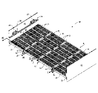
With reference to Figure 1, a portion of a screening deck 10 is
illustrated, comprising a plurality of elongate, longitudinal beams 11 each of
which is formed from an angle of steel having a long portion 12 and short
CA 02920438 2016-02-09
13
portion 13. The portions 12 and 13 are set at right angles to each other.
While the beams 11 extend in the longitudinal direction of the screening deck
10, the beams 11 can equally extend perpendicular to the direction shown.
The deck 10 illustrated in Figure 1 is a portion of a deck only and
illustrates a depth of four screening panels 15. The longitudinal length of
the
deck 10, in the direction of the beams 11 can be much greater.
The beams 11 extend parallel to one another and support the
panels 15 on the upper face of the short portion 13 of each beam 11. The
panels 15 illustrated in Figure 1 can be of any suitable size, but a common
size is 305mm by 610mm. The screening deck 10 is one part of an overall
screening apparatus. The screen deck 10 is supported on a sub frame which
includes the beams 11 and which is part of a vibratory screen machine. The
vibration that is generated is significant and requires the panels 15 to be
securely fixed to the beams 11. The panels 15 are also subject to wear over
time and even though the fixing of the panels 15 to the beam 11 are required
to be secured, the preference is that the panels are also easily releasable to
facilitate replacement.
The panels 15 include a plurality of openings through the top
surface thereof for screening product such as mining ore. The openings in
the panel can vary from large to very small depending on the screened media
required from the screening process.
Typically, ore is fed onto one end of the deck 10 and the deck is
vibrated so that the ore tends to shift from one end to the other with some of
the ore passing through the openings of the panels 15 as it travels over the
deck. Depending on the operation, the valuable ore could be the ore which
passes through the openings, or the ore which remains on the deck. The
panels 15 are attached to the screen deck 10 via elongate fixing members 20
which are mostly obscured in Figure 1, but which are shown in other figures.
The fixing members 20 are fixed to the upper surface of the short portion 13
of the beams 11 by any suitable arrangement, such as bolts. The fixing
CA 02920438 2016-02-09
14
members can extend for a single length of a single panel 15, or, more
preferably, for a greater number of panels, such as five panels.
Most of the panels 15 will be in face to face engagement along
side edges of each panel. For example, the panel marked P1 is engaged
with facing edges of other panels 15 on all four edges. It is preferred that
the
panels have this face to face engagement, in order to prevent or minimise
screening product from entering into the junction between adjacent panels 15
and through that junction to the beams 11 below or into the screened product
that is collected below the screen deck. Any entry of such screening product
between adjacent panels 15 can cause wear to the fixing members 20, or to
the beams 11, thus compromising operation of the screening deck 10. With
sufficient wear, worn components must be replaced and that results in down
time of the screening apparatus. Wear of certain components, such as the
beams 11, can require significant down time in order to replace the
components. It is therefore important that the panels 15 be fixed to the deck
10 securely and with firm side edge engagement between adjacent panels.
It is to be noted that the deck 10 includes side clamps 21 at each
side of the deck 10, and in facing engagement with side walls 22. Side
clamps 21 clamp via a bracket 23 and wedge 24 onto the upper edge surface
of the panels 15 for the purpose of preventing lifting of the facing edge of
the
panels 15, preventing ingress of screening product between the side edges
of the panels 15 and the walls 22, and also to protect the walls 22 (which are
usually steel walls), from the impact of screening product which traverses the
screen deck 10. The side clamps 21, like the panels 15, are usually made
from a polyurethane material. The side clamps 21 can be used with a
screening apparatus of the invention or with prior art screening apparatus.
The manner in which the screen panels 15 interact with the fixing
members 20 will be described hereinafter. For that discussion, it is important
to note from Figure 1, the existence of locking members 25 that assist to
locate the panels 15 relative to the fixing rails 20 against movement of the
panels 15 along the fixing rails. In this respect, while the deck 10 is shown
CA 02920438 2016-02-09
as a flat, screening decks generally operate on an incline to promote travel
of
ore from one end of the deck (the feed end) to the other (the discharge end),
and some decks incorporate inclined sections (these can be referred to as
"multi-slope decks"), in order to increase the speed of ore from the feed end
5 to the discharge end. The inclined sections can have a greater
inclination at
the start of the deck and reduce towards only a slight inclination so that
screening product decelerates from a high speed at the entry or initial
section
of the screening deck, to a lower speed when the screening deck flattens out
to a slight incline. These types of decks process the screening product more
10 quickly than decks that have only a slight and constant incline over the
length
of the deck because the screening product travels over the deck more quickly
due to the more greatly inclined sections.
Particularly in the multi-slope types of decks, there is tendency for
the screening panels to shift in the direction of screening product movement
15 due to the loads placed on the panels by the moving screening product
and
that shift can cause gaps to open between adjacent panels and for screening
product to fall through those gaps causing the problems mentioned above in
relation to wear of deck components or contamination of screened product.
For this reason, the present invention is intended to lock the panels 15
firmly
in position on the fixing members 20 in order to prevent such panel shifting
movement. That locking however is intended to be selective in that the
invention can allow movement of the panels 15 relative to the fixing members
20 to allow proper and accurate location of the panels 15 on the fixing
members 20, but once the panels 15 are correctly located, the panels can be
locked against further movement relative to the fixing members 20. This
differs from some prior art arrangements where the screening panels are
locked as soon as they are fixed to the fixing members, so that initial pre-
fixing movement along the fixing members is not provided or allowed.
With reference to Figure 2, a cross-sectional view of one full panel
15 (the central panel), and side edges of two adjacent panels 15 (to the left
and right of the central panel) is illustrated. Figures 3 and 4 are exploded
CA 02920438 2016-02-09
16
and assembled views of a single panel 15 relative to a single fixing member
20. Figures 2 to 4 show the configuration of the fixing members 20 and show
that the fixing members 20 include a pair of rails 26 which extend from a
base 27 and which are formed by webs 28 and heads 29. Recesses 30 are
defined between the base 27 and the heads 29 and it can be seen that the
side edges of the panels 15 each include a projection 31 that extends into the
recesses 30 in order for the side edges of the panels 15 to cooperate with the
rails 26 of the fixing members 20 to fix the panels 15 to the fixing members
20 and thus to the beams 11.
The side edges of the panels 15 also include a longitudinal
overhang 34 (Figure 2) that overlies the upper end of the rails 26, or in
other
words overlies the heads 29 and includes a downwardly extending portion 35
that extends into the gap G (Figure 2) between adjacent rails 26. It is
intended that facing surfaces of facing portions 35 engage tightly to prevent
ingress of screening product between the portions 35 and into the fixing
members 20.
The panels 15 are securely located on the beams 11 by
cooperation between the projection 31 of the side edges of the panels 15
within the recess 30 of the fixing members 20. The panels 15 can be
connected to the fixing members 20 by the projections 31 riding down the
inclined surface 36 of the heads 29 and by the rails 26 bending inwardly
towards each other as the projection 31 moves over the inclined surface 36
for insertion into the recess 30. With the projection 31 seated within the
recess 30, the portion 35 is positioned within the gap G, and when a pair of
panels have been assembled to the fixing member 20 as shown in Figure 2,
the respective portions 35 engage and prevent inward flexing or tipping of the
rails 26 towards each other. By this arrangement, side edges of the panels
15 are securely held in place on the fixing members 20 by the secure
engagement of the projections 31 within the recesses 30.
However, as indicated above, it is a feature of the invention that
the panels 15 are not only secured in the array formation shown in Figure 1,
CA 02920438 2016-02-09
17
but also against movement along the fixing members 20. In the illustrated
form of the invention, prevention of that latter form of movement is by the
use
of locking members 40 that fit into locating gaps which are formed in the
overhang 34 and in the rails 26. With reference to Figure 3, gaps 41 are
formed in the overhang 34, while gaps 42 are formed in the rails 26 of the
fixing member 20. The gaps 41 and 42 form a locating gap into which the
locking member can be inserted.
With reference to Figure 4, with the gaps 41 and 42 aligned, or
overlaid, the locking members 40 can be inserted and it will be appreciated
that once inserted, the locking members 40 lock the position of the panel 15
on the fixing member 20 through engagement with the edges of the gaps 41
and 42. While the locking members 40 remain in place, movement
lengthwise of the panel 15 along the fixing member 20 is not possible.
The figures mentioned above also show the manner by which the
fixing members are fixed to the beam 11 and while this is a relatively
standard arrangement, it will be briefly described as follows.
Extending from the base 27 of the fixing member 20 are a pair of
projections 45 (Figure 3) that extend through openings 46 in the portion 13 of
the beams 11 and while the projections 45 are not shown as being threaded,
they include a thread over which the washers 47 pass and on which the nuts
48 thread. The nuts 48 tighten the fixing members 20 onto the beam 11,
while a urethane cap 49 is also threaded onto the end of the 45 to protect the
fixing arrangement (the projections 45, washers 47 and the nuts 48) against
the corrosive effect of fines (very fine screening product).
The fixing members 20 can be of any length suitable to secure one
or more panels 15. Figure 5 illustrates a fixing member 50 that is of a length
suitable to fix four panels 15 thereto. It is envisaged that for commercial
use,
the fixing members 20 will have at least the length shown in Figure 5 but
potentially a greater length, although a smaller length is possible.
CA 02920438 2016-02-09
18
The locking members 40 must firmly lock into the gaps 41 and 42
and must be constructed to maintain that locking engagement under
operation of the deck 10 during a screening operation in which the deck is
vibrated. Accordingly, the locking members 40 include a construction that is
illustrated in Figures 6 and 7 and with reference to those figures, it can be
seen that the locking member 40 has a generally rectangular shape and
includes four projections or undercuts 52. Each undercut 52 projects from a
side wall or edge of the locking member 40 and includes an upper surface
53. As shown in Figure 7, two of the undercuts 52 on opposite sides of the
locking members 40 engage a downwardly facing surface 54 of the inner
edges or walls of the gaps 41 in adjacent panels 15 in order to lock the
locking members 40 in place. The other two the undercuts 52 engage a
downwardly facing surface of the other walls (the side walls) of the gaps 41
as will be below. The locking members 40 are intended to be a tight fit within
the locating gaps formed by the overlying gaps 41 and 42.
There is sufficient flexibility in the undercuts 52 in order to simply
push the locking members 40 into the gaps 41 of an adjacent pair of panels
15 with the undercuts 52 compressing or deflecting to allow the locking
members 40 to enter the gaps 41 and for the undercuts 52 to thereafter splay
or flex outwardly once the upper surface 53 has penetrated to a position just
below the downwardly facing surfaces 54. As shown in Figure 7, the bottom
face 55 of each locking member 40 rests on upwardly facing surfaces 56
(see Figures 3 and 4), of the rails 26 in the region of the gaps 42. By this
arrangement, each of the panels 15 and the locking member 40 are firmly
secured in place and because the locking member 40 is a tight fit within the
gap 42, so that it bears against facing surfaces 57 (see Figure 3) of the
heads 29 of the rails 26, longitudinal movement of the locking members 40 is
precluded and thus longitudinal movement of the panels 15 is also precluded.
While the undercuts 52 engage the surfaces 54 of the inner walls
of the panels 15 as shown in Figure 7, the undercuts 52 also engage further
downwardly facing surfaces 58 of the side walls that extend from the inner
CA 02920438 2016-02-09
19
walls as shown in Figure 3, so that the locking member 40 is secured against
release out of the gaps 41 and 42 on each of its four sides. This forms a
highly secure fitting.
Locking members 25 and 40 are illustrated in Figure 1, and from
this, it can be seen that the locking members 25 have different shapes on the
surface of the deck 10 to the locking members 40. The form of the locking
members can vary and two other forms are illustrated in more detail in Figure
8 and 9. Each of the locking members 40, 60 and 65 have the same bottom
or base end defining a rectangular shape with four undercuts 52. It is only
the upper part of the locking members that differ and in Figure 8, the locking
member 60 is shown to have a diamond shaped upper end 61, while in
Figure 9, the locking member 65 has a pyramid shaped upper end 66. The
upper ends 61 and 66 are shaped as deflectors, so that screening product
travelling along the deck 10, that travels along the adjoining sections of
adjacent panels 15 in which no screening openings exist, is deflected back
onto portions of the screening panels that do have screening openings.
Returning to Figure 1, it will be evident that the arrangement which
exists between adjacent side edges of adjacent panels 15 cannot be
employed along the walls 22 of the deck 10 because there is no adjacent
panel for the side edge panels to engage or abut. Nevertheless, is it
important to secure the panels at the edges against longitudinal movement of
the deck 10 at the side walls 22, so that the panels 15 that extend to the
side
walls 22 are also fully located against longitudinal movement. Also, it is
important to secure the panels 15 at the edges against lateral movement
toward and away from the side walls and against lifting movement away from
the beams 11 of the screen deck.
For this, the side clamps 21 have been configured so that they can
support plugs or spacers (hereinafter "plugs") for interaction with the panels
15. With reference to Figures 10 to 13, the side clamp 21 includes a rear
face 70, a front face 71, an upper stepped edge 72 which is engaged by the
wedge 24 for securing the side clamp 21 in place, and a lower or bottom
CA 02920438 2016-02-09
edge 73. Extending from the lower edge 73 are projections 74 that each
include an opening 75 for receipt of a plug 76, which is shown in side cross
sectional view in Figure 13.
From Figure 13, it can be seen that the plug 76 has a head 77, a
5 neck 78 and a base 79. The dimensions of the openings 75 are such to
snuggly or closely accept the neck 78, and the arrangement is that the base
79 is sufficiently flexible to allow it to be pushed through the smaller
diameter
opening 75 and to splay or recover once through the opening 75 to engage
against the rear surface 80 of the projections 74, with the surface 80 being
10 slightly inboard of the rear face 70 of the side clamp 21 so that
the rear of the
base 79 is coextensive with the rear face 70. The distance Di between the
bottom surface of the head 77 and the facing surface of the base 79 is also
configured to be approximately the same as the distance D2 between front
and rear surfaces of the projections 74.
15 With
reference to Figures 3 and 4, and assuming for the purposes
of the description in relation to the plugs 76, that the side edge 82 of the
panel 15 of Figures 3 and 4 is the side edge 82 shown in Figures 11 and 12,
then it will be apparent that the side edge 82 includes openings or gaps 41
(see Figures 3 and 4) that are proximate the facing surface of the wall 22.
20 The projections 74 of the side clamp 21 shown in Figure 10 are
therefore
spaced apart for alignment with the gaps 41 in the side edge 82. The
projections 74 of the side clamp 21 also have a width dimension Wi (see
Figure 10) that is the same, or just slightly smaller than the width dimension
W2 of the gaps 41 (see Figure 4). When the projections 74 are located within
the gaps 41, side edges of the projections 74 bear against facing surfaces of
the gaps 41 to locate the side edge 82 against longitudinal movement in the
direction A (see Figure 1) between the feed and discharge ends of the screen
deck 10. By this arrangement, the side edge 82 is secured against that
longitudinal movement to the same extent that that movement is secured at
the opposite ends of the panels 15 by the earlier described locking members
25, 40, 60 or 65.
CA 02920438 2016-02-09
21
The engagement should be enough to prevent longitudinal
movement of the panels 15 in the direction A of Figure 1. The fit of the
projections 74 preferably should therefore be an interference type fit within
the gaps 41. The bearing engagement can be firm engagement and the
dimensions of the projections 74 and the gaps 41 can be made so that the
panels must be forced into position on the projections 74, However, such a
tight engagement is not considered to be absolutely necessary, so that a
friction fit could be acceptable or even a slightly loose fit.
For the panels 15 to be secured against lateral movement toward
and away from the side walls 22 (movement in the direction B as shown in
Figures 3 and 4), contact must be made with the inside or base surfaces 43
of the gaps 41, It is not intended that the projections 74 will engage the
base
surfaces 43, although in some arrangements this could occur, but rather, it is
the intention that the plugs 76 engage the base surfaces 43, The plugs 76
can be made in different lengths or sizes as explained below, to
accommodate variations in the spacing between the base surfaces 43 and
the facing surface of the projections 74 of different screening decks or
machines,
The plugs 76 are proposed to be separate from the projections 74,
so that different sized plugs can be used to accommodate different spacing
between the base surfaces 43 and the facing surface of the projections 74 as
necessary. Thus, in relation to Figure 14, the side clamp 21 is again shown,
having the same features and thus the same reference numerals as the side
clamp 21 as shown in Figure 10. However, in Figures 14 and 15, plugs 84
are illustrated and those plugs have a different and reduced depth D4
compared to the depth D3 of the plug 76 of Figure 13. The plug 84 has a
head 85, a neck 86 and a base 87. The dimensions of both the neck 86 and
the base 87 can be the same as the neck 78 and the base 79 of the plug 76.
Where the dimension differs in the respective plugs 76 and 84 is in the
dimension or depth of respective heads 77 and 85. As can be seen in
CA 02920438 2016-02-09
22
Figures 13 and 15, the head 77 is of greater dimension or depth compared to
the head 85.
The dimensions of the plug 84 is for snug or close receipt of the
neck 86 within the openings 75, with the base 87 being sufficiently flexible
to
allow it to be pushed through the smaller diameter opening 75 and to splay or
recover once through the opening 75 to engage against the rear surface 80
of the projections 74 in the same manner as the plugs 76 of Figures 10 and
13.
The different sizes or depth of the plugs 76 and 84 illustrated in
Figures 10 and 14 allows compensation for slight variations in the total width
of the screening deck 10 between the opposite side walls 22 (see Figure 1).
This is important, because while the distance between the side walls 22 is
specified for each screening deck, there can be slight variation along the
length of the deck between the side walls (such as by slight bowing of the
sides walls along their length), so that the size of the plug needed to engage
the base surface 43 of the screen panels 15 can also vary. Moreover,
different screen deck manufacturers manufacture their screen decks to
different widths and where the variation between the width of the screen
decks of different manufacturers varies only by a few millimetres (say up to
30mm), the same side clamp can be used for each deck with the plugs being
selected based on the distance that the plugs need to bridge,
It is necessary for the plugs 76 and 84 to engage the base surface
43 of the gaps or openings 41. The engagement should be enough to
prevent lateral movement of the panels 15 in the direction B of Figures 3 and
4. The fit of the plugs 76 and 84 should preferably be an interference type
fit
so that the faces 89 of the plugs 76 and 84 bear against the base surfaces 43
of the gaps 41. The bearing engagement can be firm engagement. The
heads 77 and 85 can be made so that the panels must be forced into position
against the plugs 76 and 84, although such a tight engagement is not
considered to be absolutely necessary. What is necessary is that the heads
CA 02920438 2016-02-09
23
77 and 85 of the plugs 76 and 84 take up the gap between the projections 74
and the facing base surfaces 43 and bear against the base surfaces 43.
The plugs 76 and 84 can have the same width dimension W1 (see
Figure 10) as the projections 74, so that the plugs 76 and 84 can also
engage facing surfaces of the gaps 41 in the same way as the projections 74
engage facing surfaces of the gaps 41 to prevent longitudinal movement of
the panels 15 in the direction A of Figure 1. However, this is not a
requirement. Also, where the plugs 76 and 84 have the same width
dimension W1 as the projections 74, the plugs 76 and 84 might not contribute
much to the resistance of longitudinal movement of the panels 15, particularly
where the dimension of the head 77 or 85 of the plugs 76 and 84 is small.
Where the head dimension is larger, then the plugs 76 and 84 can contribute
to the resistance of longitudinal movement.
The invention described herein is susceptible to variations,
modifications and/or additions other than those specifically described and it
is
to be understood that the invention includes all such variations,
modifications
and/or additions which fall within the spirit and scope of the present
disclosure.