Note: Descriptions are shown in the official language in which they were submitted.
CA 02920446 2017-02-09
OPERATING APPARATUS FOR A BRAKE
The invention relates to an operating apparatus for a brake, in particular a
drum
brake, in particular for a utility vehicle.
Drum brakes for utility vehicles are known in the prior art. They usually
comprise an
actuator unit, which may be formed by a pneumatically or hydraulically
operated
brake cylinder, an actuating unit for displacing a brake element, which is
covered by a
brake lining, as well as a transmission unit for transmitting a force from the
actuator
unit to the actuating unit.
In so-called wedge drum brakes, a brake lining carrier with a brake lining
attached
thereto is moved radially outwards and pushed against the inner surface of a
rotating
brake drum by means of a wedge-shaped longitudinally mobile actuating element.
The axle formed by the wedge and the brake cylinder runs either parallel or
transverse to the axle of the wheel to be braked, depending on the available
space.
The transmission element arranged between the brake cylinder and the actuating
element may be dimensioned such that the brake cylinder is arranged in a
favorable
position, depending on the available building space.
Due to the dimensions of the brake cylinder, it is hardly or not at all
possible to mount
such an operating apparatus in the case of certain assemblies, which have a
limited
clearance only.
The object underlying the present invention is to provide an operating
apparatus for a
brake, which has a field of use, which is a large as possible, and which may
in
particular also be used in case the installation space is limited.
According to the invention, this object is achieved by means of an operating
apparatus having the features disclosed herein. Preferred embodiments of the
invention are indicated in the following description, in particular in
connection with the
appended Figures.
1
CA 02920446 2017-02-09
According to the invention, the operating apparatus, which may be provided in
particular for operating a drum brake, comprises an actuator unit, in
particular a brake
cylinder, with a linearly mobile actuator element, an actuating unit with a
linearly
mobile actuating element, by means of which a braking element can be moved
relative to a brake disc or a brake drum, and a transmission unit for
transmitting a
force from the actuator element or actuator unit to the actuating element or
to the
actuating unit. According to the invention, the transmission unit comprises a
deflection device, by means of which the force, which is transmitted from the
actuator
element to the actuating element, or the force, which is transmitted from the
actuator
unit to the actuating unit, can be deflected from a first direction into a
second
direction. A basic idea of the invention may be seen in that the force
transmitted
between the actuator unit and the actuating unit is deflected along an angle
so that
the orientation of the actuator unit can be realized irrespective of the
orientation of
the actuating unit. This means in particular that a longitudinal axis of the
actuator unit
may be inclined or bent relative to a longitudinal axis of the actuating unit.
In this way,
in the case of a building space, which is limited in the axial direction, the
brake
cylinder may be displaced into an area which, relative to the wheel axle, is
positioned
radially further outside. The axle of the brake cylinder or of the actuator
element runs
at an angle or non-parallel to the axis of the spreader unit or of the
actuating element.
In order to transmit the braking force from the actuator unit to the actuating
unit, a
deflection element is provided, which, according to the invention, is arranged
in the
application path between the actuator unit and the actuating unit. Due to the
deflection of the braking force or the movement of the actuator element, the
operating apparatus of the invention may also be mounted in assemblies and
suspension systems, such as swing axle assemblies, steering axles, independent
wheel suspensions or portal axles, which are demanding when it comes to
building
space requirements. Due to the concrete selection of the angle of deflection
and/or
the direction of deflection, the actuator unit may be arranged in almost any
position.
The actuating unit may be formed in particular as a spreader unit and comprise
a
longitudinally mobile wedge as actuating element. The deflection may be done
basically in any way. For example, it is conceivable to arrange between the
actuator
2
CA 02920446 2016-02-04
element and the actuating element a freely mobile coupling element, such as a
coupling rod, along which the force is transmitted from the actuator element
to the
actuating element.
According to the invention, it is preferred that the deflection device has a
deflection
element, which is rotatably mounted about an in particular stationary axis of
rotation
and which comprises at least two coupling devices, which are displaced or
offset
relative to each other in the direction of rotation, for coupling respective
force
transmission elements. Due to the rotation element mounted on an axis of
rotation
the force may be reliably and precisely deflected, wherein there is a
mechanical
support on the axis of rotation of the deflection element. The transverse
forces acting
on the actuator element and on the actuating element may be reduced in this
manner. The force transmission elements may be in particular the actuator
element
and the actuating element, wherein basically also a separate force
transmission
element may be interconnected. The coupling devices may be formed in
particular as
contact surfaces for the transmission of force.
In order to transmit the force into the deflection element, in particular a
first coupling
device or contact surface may be provided, onto which the actuator element or
a
force transmission element connected thereto acts. In order to transmit the
force from
the deflection element to the actuating element or a force transmission
element
connected thereto, in particular a second coupling device or contact surface
may be
provided.
Preferably, the coupling devices are displaced relative to each other in the
circumferential direction at an angle of 200 to 120 , particularly preferably
750 to 105 .
Within the context of the present invention, circumferential direction means
preferably
a circular path, which runs about the axis of rotation of the deflection
element and
which runs through at least one of the coupling devices. The preferred angles
are
thus to be measured between a first straight, which runs through the first
coupling
device and the axis of rotation, and a second straight, which runs through the
second
coupling device and the axis of rotation. Accordingly, the angle of
inclination between
the axis of the actuator unit and the axis of the actuating unit is preferably
20 to
120 , particularly preferably 75 to 105'. The mentioned angles ensure a
reliable
3
CA 02920446 2016-03-23
transmission of the braking force into the actuating element and allow for an
advantageous mounting position of the actuator unit for a plurality of uses.
In order to provide a leverage or a gear ratio increase or a gear reduction
between
the actuator unit and the actuating unit it is preferred that the distances
between the
coupling devices and the axis of rotation of the deflection element are
different. The
different lever lengths, which are formed by the different distances from the
axis of
rotation, make it for example possible to easily realize an increase in
braking force.
Particularly preferably, the deflection element has different lever lengths
and an angle
between the lever arms, which is smaller 1800, preferably smaller 120 . In
this way, in
the case of a very compact design of the operating apparatus, great braking
forces or
great operation paths may be achieved.
The deflection element may be disc-shaped, for example. A particularly stable
and
weight-reduced deflection element may be achieved in that the deflection
element
has at least two essentially radially extending pivoted levers, on which the
coupling
devices are formed. The preferably V-shaped deflection element is mounted at
its
vertex at a preferably stationary axis of rotation.
In a preferred embodiment of the invention, at least one of the coupling
devices is
formed as a hinge connection. Preferably, a force transmission element is
mechanically connected to the deflection element by means of a hinge, wherein
a
force is transmittable. The force transmission element may be in particular
the
actuator element or the actuating element or a part thereof.
In order to transmit the force from the actuator element to the rotating
deflection
element or from the rotating deflection element to the actuating element, the
actuator
element and/or the actuating element may have a linearly mobile base body and
a
transmission head pivotably mounted thereon. The transmission head may be
coupled to the deflection element by means of a hinge connection.
Alternatively, it
may also be provided to mount the hinge radially mobile in order to ensure a
balance
between the rotational movement of the deflection element and the linear
movement
of the actuator element or of the actuating element.
4
CA 02920446 2016-02-04
Instead of a defined pivot point at least one of the coupling devices may have
a
sliding or rolling surface, along which a force transmission element, in
particular in
the radial direction is mobile, in particular slidable or rollable. In the
context of the
present invention, radial direction means preferably a parallel to a straight,
which
runs through one of the coupling devices and the axis of rotation. In this
way, it is
possible to do without a balancing force transmission head of the actuator
element
and/or of the actuating element.
A particularly sturdy and low-maintenance operating apparatus may be provided
in
that the actuating unit and the transmission unit are accommodated in a common
housing. The housing encloses preferably the deflection element as well as
preferably the actuating element, which preferably has a wedge. Preferably,
the
housing is in addition flanged directly to a housing of the actuator unit.
This effectively
prevents the entry of dirt into the deflection device. Particularly
preferably, the
common housing is formed one-piece. Preferably, the common housing is a once-
piece casting, which may be manufactured particularly easily.
Preferably, a fastening device is provided, which makes it possible to attach
the
operating apparatus to an axle element of the wheel to be braked in different
rotational positions about the longitudinal axis or actuating axle of the
actuating
element and/or a wheel axle of an axle element of a wheel to be braked. Due to
this
variable possibility of attachment, the actuator unit may be arranged flexibly
in the
space about the longitudinal axis of the actuating element and/or the wheel
axle. The
area of use of the actuating device is thus further enlarged. In particular, a
housing of
the operating apparatus may have a fastening or contact surface, which at
least
partially extends about the actuating axle. The fastening surface may be
formed as a
curved surface, for example, or comprise at least two partial surfaces, which
are
positioned at an angle relative to each other.
In a further preferred embodiment, the deflection device causes the force to
be
deflected in a plane, which is spanned by a wheel axle of an axle element of a
wheel
to be braked and a perpendicular to the wheel axle. The perpendicular to the
wheel
axle is preferably parallel to the vertical, wherein the axle element is
preferably
arranged essentially horizontally. Thus, the deflection is done in a plane,
which
5
CA 02920446 2016-02-04
contains the longitudinal axis of the axle element. Preferably, a longitudinal
axis of
the actuator unit or of the actuator element (actuator axle) is oriented such
that it
intersects the longitudinal axis of the axle element (wheel axle).
However, the invention makes it also possible that the deflection is done in a
plane,
which is intersected by the longitudinal axis of the axle element or which is
arranged
parallel to the longitudinal axis. A room-saving arrangement of the actuator
unit may
be achieved in particular in that the actuator unit has a longitudinal axis
(actuator
axle), which is inclined relative to the radius of the axle element of the
wheel to be
braked and/or in that the actuator axle and the wheel axle are skew relative
to each
other.
The invention offers in particular the following advantages:
1. Due to the force deflection a very compact, light-weight and cost-optimized
brake
device may be realized, which may in particular be formed as a spread brake or
as a
wedge brake.
2. The integrated deflection device does not require any additional
interfaces, which
might interfere with the tightness.
3. Due to the deflection device integrated into the housing of the actuating
unit, the
cylinder weight is absorbed by a common, rigid housing, which is firmly
connected to
the axle body.
4. It is possible to use standard components, which only need to be
supplemented by
the parts of the deflection.
5. It is possible to use the same brake cylinders as for a spreader unit or an
actuating
unit without deflection.
6. Due to the integrated deflection, no outer linkage is necessary, which
might react
sensitively to outer influences, thus reducing the reliability of the brake.
6
CA 02920446 2016-02-04
7. The wedge unit remains low-maintenance.
8. The wedge unit may be completely pre-mounted independent of the brake.
9. Several brake sizes may be covered, as is the case for wedge units without
deflection.
10. A single-piece housing may be realized for the complete spreader unit
including
deflection.
The invention will be described in more detail hereinafter with the help of an
exemplary embodiment, which is shown in the appended Figures.
The Figures show:
Fig. 1 shows a longitudinal section through an operating apparatus according
to the
invention of a drtim brake, and
Fig. 2 shows a cross-section through an operating apparatus according to the
invention of a drum brake.
Similar components or components having the same effect have the same
reference
signs in the Figures.
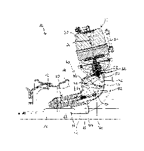
An exemplary embodiment of an operating apparatus 10 according to the
invention,
which is to be considered basically as a part of a brake, in particular a drum
brake,
will be described hereinafter with reference to Figs. 1 and 2.
The operating apparatus 10 comprises an actuator unit 20, which is formed as a
pneumatic brake cylinder and which has an actuator housing 30. In the actuator
housing 30, an actuator element 22 is mounted longitudinally mobile along an
actuator axle 26. In order to pneumatically drive the actuator element 22, a
compressed air supply 34 is provided. The actuator element is mobile against a
7
CA 02920446 2016-02-04
spring force, which moves the actuator element 22 against the compressed air
into a
return position.
An actuating unit 60, which may also be referred to as spreader unit,
comprises an
actuating element 62, which is linearly mobile along an actuating axle 66 and
which
has a wedge, which is not shown in the Figures. By linearly moving the wedge
along
the actuating axle 66, a brake element may be pushed radially against the
inside of a
brake drum 12 in order to carry out a braking operation. The brake drum 12 is
firmly
connected to a rim 14 of a wheel to be braked and rotates together with the
latter
about a particularly rigid or stationarily mounted axle element 16 with a
wheel axle
18. The actuating axle 66 of the actuating element 62 runs at an angle to the
wheel
axle 18.
In order to transmit the braking force from the actuator element 22 to the
actuating
element 62, in the application path between the actuator unit 20 and the
actuating
unit 60, a transmission unit 40 with a force transmission element is arranged.
The
transmission unit 40 comprises a deflection device 42, by means of which the
effective direction of the braking force is deflected from the actuator axle
26 into the
actuating axle 66, which runs transverse or at an angle hereto.
The actuator element 22 pushes against a deflection element 44, which is
rotatably
mounted about an axis of rotation 46, causing a rotation of the deflection
element 44
about the axis of rotation 46. The deflection element 44 pushes against the
actuating
element 62 of the actuating unit 60 and causes a linear displacement of the
actuating
element 62. A braking force is thus transmitted from the actuator element 22
to the
actuating element 62.
The preferably V-shaped deflection element 44 comprises two pivoted levers 50,
52,
which run at an angle relative to each other and which have respective
coupling
devices 54, 56, such as a coupling surface or a coupling joint. The actuator
element
22 is connected to a first coupling device 54 of the deflection element 44,
and the
actuating element 62 is connected to a second coupling device 56 of the
deflection
element 44.
8
CA 02920446 2016-03-23
The first coupling device 54, which is formed at a first pivoted lever 50, has
a contact
surface, which is formed as a groove-shaped or tub-shaped cavity. The actuator
element 22 comprises a pressure or head element 24, which is in particular
mounted
pivotably at one front face and which has an accordingly formed contact
surface,
which may be cylinder-shaped or spherical, for example. The head element 24
engages into the cavity of the deflection element 44 in order to transmit a
compressive force.
A second coupling device 56 provided on a second pivoted lever 52 comprises a
hinge, to which the actuating element 62 is coupled. In order to transmit the
force to
the linearly mobile actuating element 62, the actuating element 62 comprises a
transmission head 64, which is movably mounted on a base body. Apart from
transmitting compressive forces, the hinge makes it possible to also transmit
tensile
forces, for example in order to cause the actuating element 62 to return. The
deflection element 44 may be pretensioned by means of a spring force, against
which
the braking force acts.
The deflection element 44 and the actuating element 62 are accommodated in a
common housing 70. The actuator housing 30 of the actuator unit 20 is flanged
directly to the housing 70 by means of a flange 32. In this way, the
transmission
mechanism for transmitting the braking force from the actuator unit 20 to the
wedge
unit or actuating unit 60 is well protected against outer influences.
The housing 70 is designed such that the actuator unit 20 may be arranged in
different rotational positions about the wheel axle 18 and in different
rotational
positions about the actuating axle 66. To this end, a first fastening area 72
is provided
for attaching the housing 70 to the axle element 16. The fastening area 72 is
designed such that the housing 70 may be arranged in different rotational
positions y
about the wheel axle 18 and be attached thereto. A second fastening area 74
allows
for different rotational positions y of the actuator unit 20 relative to the
actuating axle
66.
9
CA 02920446 2016-02-04
Due to the deflection according to the invention constructive freedoms of
design are
provided, which by varying the below-mentioned parameters allow for almost any
cylinder position:
a: axial inclination of the spreader unit or actuating unit, in particular
of the
actuating axle, relative to the wheel axle, preferably between +1- 300, more
preferably
between +/- 15 (cf. Fig. 1);
13: inclination of the brake cylinder, in particular of the actuator axle
relative to the
spreader unit or actuating axle, in particular in the deflection plane,
preferably
between +45 and +135 , more preferably between +75 and +105 (cf. Fig. 1);
y: rotational position of the operating apparatus or of the brake about
the wheel
axle, preferably between 0 and 360 (cf. Fig. 2); the operating apparatus may
preferably be arranged in different rotational positions, preferably stage-
less,
distributed along the wheel axle;
6: rotational position of the operating apparatus or of the brake
cylinder or of the
actuator axle relative to the actuating unit or spreader unit, in particular
about the
actuating axle, preferably between -90 and +90 , more preferably between -15
and
+90 (in particular relative to a plane, which contains the wheel axle and the
actuating
axle) (cf. Fig. 2);
11: lever length of the deflection lever or pivoted lever connected to the
actuating or
spreader unit, preferably between 20 mm and 100 mm, particularly preferably
between 40 mm and 80 mm (cf. Fig. 1);
12: lever length of the deflection lever or pivoted lever connected to the
brake
cylinder, preferably between 15 mm and 200 mm, particularly preferably between
30
mm and 160 mm (cf. Fig. 1).
The relationship 12/11 is preferably in a range of 0.5-2.5, more preferably
between 0.75
and 2.0, and most preferably between 1 and 1.7.
CA 02920446 2016-02-04
Basically, it is also possible to use a separate deflection device, which is
to be
attached to an existing cylinder interface.
On the whole, the invention provides a particularly flexibly usable operating
apparatus, which may also be used in assemblies, which are demanding when it
comes to building space requirements.
List of reference signs
10 operating apparatus
12 brake drum
14 rim
16 axle element
18 wheel axle
20 actuator unit
22 actuator element
24 head element
26 actuator axle
30 actuator housing
32 flange
34 compressed air supply
40 transmission unit
42 deflection device
44 deflection element
46 axis of rotation
50 pivoted lever
52 pivoted lever
54 first coupling device
56 second coupling device
60 actuating unit
62 actuating element
64 transmission head
66 actuating axle
70 housing
11
CA 02920446 2016-02-04
72 fastening area
74 fastening area
12