Note: Descriptions are shown in the official language in which they were submitted.
CA 02920552 2016-02-11
-1-
LOCKING DEVICE WITH CONFIGURABLE ELECTRICAL CONNECTOR KEY AND
INTERNAL CIRCUIT BOARD FOR ELECTRONIC DOOR LOCKS
Background Of The Invention
1. Field of the Invention
[0001] The present invention relates to devices for making electrical
connections to electrical
components within electronic door locks. More specifically, the present
invention relates to a
shaped electrical connector that keys into an electronic door lock and can be
configured during
manufacture to carry electrical signals to and/or from selected electrical
sensors, actuators and/or
other components residing on a circuit board within the lock. The circuit
board may reside on an
surface inside the lock and/or may be embedded inside the lock to provide
electrification thereto.
Electrical components available for use within the door lock are selected
based on the particularly
selected configured electrical connector key.
2. Description of Related Art
[0002] Various types of access-control technology devices are available for
use with, on or inside
a door. For instance, it is know to use access-control technology in locking
devices. Access-control
technology in locking devices has increasingly shifted from traditional keying
systems and
mechanical articulation to digital monitoring and electronic actuation.
Various electronically
actuated locks and exit devices for doors exist in the art. These
electronically actuated locks are
generally classified into two categories, namely, those having electronic
circuitry housed inside a
CA 02920552 2016-02-11
-2-
mortised recess of a door, and those having electronic circuitry housed in an
escutcheon-type lock
assembly.
[0003] A variety of electronic components, such as sensors, actuators and
other electronic
components, may be provided in electronic door locks. The components may
include actuators, such
as motors, solenoids, linear drivers, and the like that operate electrically
and allow the lock to be
remotely locked or unlocked. The electronic door lock will also typically
include one or more
sensors positioned within the lock to detect and signal the position of
various lock components, such
as the latchbolt, the deadbolt, the locked or unlocked status of the lock, the
position of the door
relative to the door frame (door open or closed), and the like. The electronic
door lock may also be
provided with other kinds of auxiliary electronic components, such as
microcontrollers and
memory, and the like.
[0004] For many electronic door lock designs, the electronic components within
the lock are
electrically connected to an external control unit located outside the lock,
such as a door lock
control system, a building security system, an emergency fire control system
or monitoring system,
and the like. The connection from the inside of the lock to the external
control unit is typically
made via intricate wiring that connect through a wiring harness to the
external control unit. This
entails routing wiring from the external electronic circuitry, into the lock,
and discretely throughout
the lock in a pattern that avoids the mechanical working components of the
lock. The routed wiring
inside the lock is connected to switches and actuators residing therein for
providing an
electronically actuated and monitored lock.
CA 02920552 2016-02-11
-3-
[0005] Electronic door locks may include different configurations of actuators
and sensors that
must be provided with matching wiring harnesses to allow connection of each of
the specified
components ¨ sensors, actuators, and the like - to the external control unit.
Often, these
configurations are individually assembled, and a matching wiring harness
prepared and connected to
the internal electronic lock components by hand. Problems arise in making
multiple connections
between the electronic door lock components and an external control unit. Such
problems also
encompass the connectors, the wiring harness and the selection of sensors
within the lock that are to
be made available to the external control unit.
[0006] The sensors may be contact switches, magnetically operated reed
switches, Hall effect
sensors and/or other types of sensors. Usually, such sensors are located to
signal the position of
mechanical components within the lock and/or the door. The sensors may be used
to indicate
whether the door lock is in the locked or unlocked state. They may indicate if
the latchbolt is
extended or retracted, or whether the door on which the lock is installed is
open or closed. They
may monitor the position of a deadbolt, the rotation of a handle or signal
whether the lock has
performed other functions.
10007] In addition to the sensors, there may be different actuators within the
electronic lock.
Many different actuators exist and may include a motor, a linear driver, a
solenoid, a solenoid
emulator in the form of a stepping motor or stepping motor integrated into a
linear actuator, and the
like. The most common types of actuators are 12 volt or 24 volt solenoids that
may be "fail safe" (if
power is lost the door defaults to unlocked) or "fail secure" (defaults to
locked).
CA 02920552 2016-02-11
-4-
[0008] Solenoid designs are typically intended for use with centralized
building control systems
where the external control unit is centrally located and is connected to
multiple electronic locks with
wires. The external control unit sends a simple on or off power signal to lock
or unlock each
electronic lock by switching it away from its default state when power is
applied. When power is
removed, the lock returns to its default state. In the "solenoid" type
designs, actual solenoids may
be used or solenoid emulation may be used in which a motor, linear driver, or
other actuator
responds to the same type of simple "on power" vs. "off power" control signal.
[0009] Motorized electronic lock designs are most commonly used with an
external control unit
mounted on or immediately adjacent to the door. Typical applications for this
type of low power
motor actuator electronic lock include hotels, secure buildings, and the like
where a card key reader,
secure proximity detector, keypad, biometric (fingerprint, iris scan, voice
recognition, and the like)
is located in the external control unit. The external control unit may be
located in one or more
additional housings mounted on the door, and may also include batteries to
provide power through
wired connections to the electronic lock. Wires extend from the sensors in the
lock to the external
control unit to provide information to the external control unit about the
status of the lock. Wires
may also carry control signals from the external control unit to actuators in
the electronic lock to
lock or unlock the door in response to the presentation of security
credentials.
[0010] Various other electronic door lock designs exist, each provided with a
wide variety of
available actuators and sensors to meet various needs. Regardless of whether
the external control
unit is mounted in close proximity to the lock, wiring for all of these
different components actuators
and sensors must exit the lock housing as is common for motorized and battery
powered locks or in
CA 02920552 2016-02-11
-5-
a more distant central location as is typical for solenoid locks. The numerous
possible variations in
lock configuration results in many different wiring harnesses and typically
requires each of the
sensors to be manually installed and connected. This is labor intensive and
expensive as well as
making it difficult to keep the many variations in stock for rapid delivery to
customers.
[0011] Due to constrained real estate in a majority of currently available
locks, it has also become
difficult and burdensome to provide the necessary wiring into and throughout
the lock for the
electrical connection between the switches, sensors and actuators in the lock
and the electronic
circuitry external to the lock. Concerns are also raised when too much
electrical wiring resides
external to the locking device. Insulated wire harnesses routed through a
lockbody are subject to
damage from contact with mechanical components.
[0012] It is also undesirably burdensome, time consuming, expensive and
expends valuable real
estate within the lock by requiring the lock casing to be fabricated with a
number of holes and slots
for accommodating the inserted wiring, as well as to be fabricated with
brackets or harnesses inside
the lock for securing and positioning the wiring accommodated therein. As
such, these
conventional mortised recess and escutcheon-type lock assemblies suffer from
fabrication
difficulties as well as performance limitations in providing accurate wire
routing to switches,
actuators, and wire harnesses within existing mechanical lock mechanisms
having constrained real
estate.
[0013] In view of the above, there is a need for improved wiring harness and
connection systems
that reduce the manual interconnection and wiring required for electronic
locks having different
CA 02920552 2016-02-11
-6-
sensors and actuators. Needs also exist for these improved wiring harness and
connection systems
to allow digital monitoring and electronic actuation to be implemented in
current locking devices
that have constrained real estate. This constrained real estate may be due to
more compact designs,
or even those existing mechanical lock mechanisms having increased and/or
improved technological
advances residing inside the lock that consume an increased and/or substantial
portion of the
valuable real estate therein.
Summary of the Invention
[0014] The present invention relates to connectors, the wiring harness and the
selection of sensors
within the lock that are to be made available to the external control unit.
[0015] Bearing in mind the problems and deficiencies of the prior art, it is
therefore an object of
the present invention to provide methods and apparatus for fabricating access-
control technology as
electrified access-control technology having embedded circuitry therein.
[0016] It is another object of the present invention to provide methods and
apparatus for
converting currently existing mechanically operated access-control technology
into digitally
monitored and electrically controlled and actuated access-control technology.
[0017] Another object of the present invention is to provide methods and
apparatus for converting
an existing mechanical access-control technology device for a door into an
electrified access-control
technology device for a door that has capabilities for digital monitoring and
electronic control and
actuation.
CA 02920552 2016-02-11
-7-
[0018] It is yet another object of the present invention to provide methods
and apparatus for
converting an existing mechanical lock into an electrified lock having
capabilities for digital
monitoring and electronic actuation.
[0019] A further object of the invention is to provide methods and apparatus
for easily and
efficiently electrifying existing access-control technology (e.g., an existing
mechanical lock) having
constrained real estate.
[0020] Still another object of the invention is to provide methods and
apparatus for easily and
efficiently providing existing access-control technology (e.g., an existing
mechanical lock) with
increased performance capabilities by securing a printed circuit board within
the mechanical lock
housing.
[0021] It is another object of the present invention to provide a unified
design that allows for
alternate circuit boards to be developed, which accomplishes different
functions (i.e. modularity and
future-proofing).
[0022] Another object of the present invention is to provide methods and
apparatus for
electrifying existing access-control technology (e.g., an existing mechanical
lock) easily, efficiently
and cost effectively.
[0023] Still other objects and advantages of the invention will in part be
obvious and will in part
be apparent from the specification.
CA 02920552 2016-02-11
-8-
[0024] The above and other objects, which will be apparent to those skilled in
the art, are
achieved in the present invention which is directed to a mortise lock
comprising a lock having a hub
rotatable by a handle to open and close a latchbolt, with the hub having a
slot therein, and a locking
member moveable into and out of engagement with the hub slot alternately to
prevent and permit
movement of the hub and latchbolt. A sensor on the lock adjacent the hub and
locking member
monitors a moving lock component. The sensor may comprise a reed switch
capable of being
actuated by a magnet on the moving lock component. The lock may further
include a magnet
mounted on the hub and the sensor may comprise a reed switch capable of being
actuated by the
magnet on the hub.
[0025] In another aspect the present invention is directed to a method of
monitoring a lock
comprising providing a lock having a hub rotatable by a handle to open and
close a latchbolt, the
hub being alternately lockable and unlockable to prevent and permit movement
of the hub and
latchbolt, and providing a sensor for sensing whether the hub is locked. The
method then includes
monitoring the sensor to determine whether the hub is locked or unlocked.
[0026] The hub may have a slot therein, and the lock may further include a
locking member
moveable into and out of engagement with the hub slot alternately to prevent
and permit movement
of the hub and latchbolt. The sensor may sense the position of the locking
member and the
monitoring the sensor may be to determine whether the locking member is in or
out of engagement
with the hub slot. There may be further included a magnet connected to the
locking member and
moveable therewith between a first position wherein the locking member is in
engagement with the
hub slot and a second position wherein the locking member is out of engagement
with the hub slot.
CA 02920552 2016-02-11
-9-
The sensor may sense the position of the locking member magnet. The sensor may
comprise a reed
switch or a Hall effect sensor.
[0027] An alarm may be included, and the method may include activating the
alarm if the sensor
determines that the locking member is out of engagement with the hub slot. The
lock may be an
electrified lock having an actuator to move the locking member into and out of
engagement with the
hub slot and there may be an external control unit for sending a signal to
activate the actuator to
move the locking member into or out of engagement with the hub slot. The alarm
may be activated
if the external control unit has not sent a signal to activate the actuator to
move the locking member
out of engagement with the hub slot.
[0028] The lock may have an external member covering at least a portion of the
lock and the
method may include providing a sensor for sensing whether the external member
has been removed
from the lock and monitoring the external member sensor to determine whether
the external
member has been removed from the lock. The alarm may be activated if the
locking member
position sensor determines that the locking member is out of engagement with
the hub slot and the
external member sensor determines that the external member has been removed
from the lock. The
lock external member may be an escutcheons lock trim, card reader, keypad or
the like.
[0029] The lock may be connected to the external control unit by a removable
electrical
connector and the method may include providing a sensor for sensing whether
the electrical
connector has been removed from the lock and monitoring the electrical
connector sensor to
determine whether the electrical connector has been removed from the lock. The
alarm may be
CA 02920552 2016-02-11
-10-
activated if the locking member position sensor determines that the locking
member is out of
engagement with the hub slot and the electrical connector sensor determines
that the electrical
connector has been removed from the lock.
[0030] A further aspect of the present invention is directed to a mortise lock
comprising a lock
having a hub rotatable by a handle to open and close a latchbolt, the hub
having a slot therein, and a
locking member moveable into and out of engagement with the hub slot
alternately to prevent and
permit movement of the hub and latchbolt. A sensor senses the position of the
locking member in
or out of engagement with the hub slot.
[0031] The lock may further include a magnet connected to the locking member
and moveable
therewith between a first position wherein the locking member is in engagement
with the hub slot
and a second position wherein the locking member is out of engagement with the
hub slot. The
sensor may comprise a reed switch capable of sensing the position of the
locking member magnet.
[0032] The present invention is also directed to a method of monitoring an
electronic lock,
wherein the lock has a plurality of electrical components mounted therein. The
method comprises
providing an external control unit for controlling operation of the lock, the
external control unit
including an alarm, providing an electrical connector removably engageable
with the lock, the
electrical connector being connectible to the electrical components in the
lock and to the external
control unit, and providing a sensor for sensing whether the electrical
connector is engaged with the
lock. The method then includes monitoring the sensor to determine whether the
electrical connector
CA 02920552 2016-02-11
-11-
is out of engagement with the lock and activating the alarm if the sensor
determines that the
electrical connector is out of engagement with the lock.
[0033] The electrical connector may be an electrical connector key that is
selectively connectible
=
to each of the electrical components in the lock. The sensor may be in the
external control unit, so
that the lock sends a signal to the external control unit when the lock
connector key is engaged with
the lock, and the sensor monitors the presence of the signal and detects when
the signal is absent to
indicate that the electrical connector is out of engagement with the lock.
[0034] In yet another aspect the present invention provides a method of
monitoring a lock
comprising providing a lock having a locking mechanism moveable between
latched and unlatched
positions, and providing a pair of sensors on the lock. One sensor may be
activated when the
locking mechanism is in the latched position and the other sensor may be
activated when the
locking mechanism is in the unlatched position. The method includes monitoring
signals from the
sensors to determine activation thereof, detecting simultaneous activation of
both sensors, and
sending an alarm signal if the simultaneous activation of both sensors is
detected.
[0035] The locking mechanism may have a magnet thereon. The method may include
providing
a pair of single throw reed switches on the lock. One reed switch may be
activated by the magnet
and send a latched position signal when the locking mechanism is in the
latched position. The other
reed switch may be activated by the magnet and send an unlatched position
signal when the locking
mechanism is in the unlatched position. The method may further include
monitoring signals from
the reed switches, detecting simultaneous latched and unlatched position
signals from the reed
CA 02920552 2016-02-11
-12-
switches, and sending an alarm signal if simultaneous latched and unlatched
position signals are
detected from the reed switches. The locking mechanism may be a deadbolt.
[0036] The present invention in a further aspect is directed to a lock system
comprising a lock
housing, a locking mechanism in the housing moveable between latched and
unlatched positions,
and a pair of sensors on the lock housing or locking mechanism. One sensor may
be adapted to be
activated and send a latched position signal when the locking mechanism is in
the latched position.
The other sensor may be adapted to be activated and send an unlatched position
signal when the
locking mechanism is in the unlatched position. An external control unit may
monitor signals from
the sensors to determine activation thereof. The external control unit may
include an alarm, and the
external control unit may be adapted to detect simultaneous activation of both
sensors and send an
alarm signal if the simultaneous activation of both sensors is detected.
[0037] The lock may be a mortise lock, the locking mechanism may comprise a
deadbolt having a
magnet thereon and the sensors may comprise a pair of single throw reed
switches on the lock. One
reed switch may be adapted to be activated by the magnet and send a latched
position signal when
the deadbolt is in the latched position. The other reed switch may be adapted
to be activated by the
magnet and send an unlatched position signal when the deadbolt is in the
unlatched position. The
external control unit may be adapted to send an alarm signal if simultaneous
latched and unlatched
position signals are detected from the reed switches.
[0038] Another aspect of the present invention is directed to a method of
monitoring a lock
comprising providing a lock having a locking mechanism moveable between
latched and unlatched
CA 02920552 2016-02-11
-13-
positions and providing an actuator to move the locking mechanism between the
latched and
unlatched positions. The actuator may be activated by a command signal to move
the locking
mechanism between the latched and unlatched position. The method also includes
providing a pair
of sensors on the lock. One sensor may be activated when the locking mechanism
is in the latched
position and the other sensor may be activated when the locking mechanism is
in the unlatched
position. The method may further include monitoring signals from the sensors
to determine
activation of the other sensor indicating that the locking mechanism is in the
unlatched position, and
sending an alarm signal if a command signal was not previously sent to the
actuator to move the
locking mechanism to the unlatched position.
[00391 The present invention also provides a method of monitoring a lock
having a locked state
and an unlocked state comprising detecting a first signal to indicate a locked
state of the lock,
detecting a second signal to indicate an unlocked state of the lock, and
detecting the simultaneous
absence of the first signal and the second signal to indicate malfunction or
tampering of the lock.
The method may further include sending an alarm signal if the simultaneous
absence of the first
signal and the second signal is detected. The alarm signal may be sent if the
simultaneous absence
of the first signal and the second signal is detected after a predetermined
period of time has elapsed.
The lock may have a deadbolt moveable between latched and unlatched positions
so that the first
and second signals may indicate the deadbolt latched and unlatched positions,
respectively, and the
simultaneous absence of the first signal and the second signal may indicate a
position of the
deadbolt between the latched and unlatched positions.
CA 02920552 2016-02-11
-14-
[0040] In still other aspects, the invention is directed to an electrified
access-control device that
includes a housing having at least one side with an internal surface facing an
inside of the housing
and an access-control device residing in the inside of the housing. A channel
resides in the internal
surface of the at least one side inside the housing, and a printed circuit
board (PCB) resides within
the channel inside the housing. The PCB has various electrical components
attached thereto for
electrifying the access-control device.
[0041] In one or more embodiments, the access-control device may be a lock
that is electrified by
the PCB, whereby the electrified lock is provided with both digital monitoring
and electronic
actuation capabilities. Such locks may include, but are not limited to, a
mortise lock, a bored lock, a
cylindrical lock, a tubular lock, an auxiliary lock, and a deadbolt. In
alternative embodiments, the
access-control device may be an exit device, an electronic door strike, a door
closer, or a door
operator. In one or more embodiments the channel is embedded within the
internal surface of the
housing side, whereby the PCB has a configuration matching the embedded
channel's configuration
so that the PCB is matingly embedded within the recessed channel. The exposed
surface of the
embedded PCB may be planar with a surface of the at least one side, whereby
the embedded PCB
covers over a distance of more than 50% of a diagonal distance across a
surface area of the internal
surface of the housing side.
100421 Also in one or more embodiments, a plurality of channels may reside on
the internal
surface of the at least one side inside the housing, along with a plurality of
PCBs corresponding to
configurations of each of the plurality of channels. The plurality of PCBs may
be embedded within
respective ones of the plurality of channels inside the housing. Various
electrical components may
CA 02920552 2016-02-11
-15-
be attached to the plurality of embedded PCBs for electrifying the access-
control device. In one or
more embodiments, the various electrical components attached to the embedded
PCBs may include,
but are not limited to, one or more sensors, actuators, surface mount
connectors, signal output
devices, accelerometers, temperature sensors, heating components, and
combinations thereof.
[0043] In other aspects, the invention is directed to an electrified access-
control device for a door
that includes a housing having a first side and a second side, whereby each of
the first and second
sides have corresponding internal surfaces facing an inside of the housing,
with n access-control
device being a lock residing inside the housing. At least one recessed channel
resides in the internal
surface of either the first or second side of the housing, while at least one
PCB is embedded within
the recessed channel in the internal surface of either the first or second
side of the housing. A
variety of electrical components are attached to the PCB to electrify the
lock.
[0044] In the one or more embodiments of the invention, the variety of
electrical components
may provide the electrified lock with digital monitoring and/or electronic
actuation capabilities,
while the electrified lock may include, but is not limited to, a mortise lock,
a bored lock, a
cylindrical lock, a tubular lock, an auxiliary lock, or a deadbolt. The at
least one embedded PCB
may be a single PCB having a sinusoidal shape that covers over a distance of
more than 50% of a
diagonal distance across a surface area of the internal surface of the housing
side in which the PCB
is embedded. In one or more embodiments an exposed surface of the at least one
recessed channel
may have one or more openings therein to access a backside of the at least one
PCB. The at least
one recessed channel and the at least one embedded PCB may have matching
configurations,
whereby these matching configurations avoid interference with working
components of the lock
CA 02920552 2016-02-11
- 1 6-
and/or openings in the housing. An exposed surface of the embedded PCB may be
planar with an
exposed surface of the internal surface of the housing side in which the PCB
is embedded.
[0045] In further embodiments of the invention, the variety of electrical
components include one
or more sensors residing on the PCB and positioned at various locations across
the PCB, the various
locations corresponding to locations where one or more magnets reside on
mechanical working
components of the lock, whereby the one or more sensors sense the one or more
magnets to detect
positions of the mechanical working components of the lock. These sensors may
include, but arc
not limited to, non-contact sensors, analogue transducers, hall sensors,
electrical switches, reed
switches, reed sensors, and combinations thereof. One or more of these sensors
may be raised away
from an exposed surface of the PCB to sense the one or more magnets residing
adjacent an opposing
side of the housing. The variety of electrical components may also include one
or more sensors that
do not require a magnet for triggering.
[0046] In still further embodiments, the variety of electrical components may
include an actuator
residing inside the housing and in electrical communication with the PCB. This
actuator may be,
but is not limited to, a solenoid, motor, brush DC motor, stepper motor, piezo
motor, and shape
memory actuator. The variety of electrical components may also include one or
more surface
mount connectors attached to the PCB. In one or more embodiments the
electrical components may
include one or more electrical components surface mounted to a surface of the
PCB including, but
not limited to, an accelerometer, temperature sensors, heating components, and
combinations
thereof. The electrical components may also include one or more signal output
device connected to
the PCB, whereby the signal output device converts various electrical outputs
signals from the PCB
CA 02920552 2016-02-11
-17-
into one or more digital output signals. For instance, the signal output
device may be a controller
board or a wire harness.
[0047] Also in one or more embodiments, the electrified access-control device
may include a
plurality of channels recessed within one or more of the first or second sides
of the housing, along
with a plurality of PCBs corresponding to configurations of the plurality of
recessed channels,
whereby each of the plurality of PCBs is embedded within respective ones of
the plurality of
recessed channels. The various electrical components attached to the plurality
of embedded PCBs
electrify the lock. These plurality of embedded PCBs may reside on the first
side alone, the second
side alone, or both the first and second sides of the housing, whereby the
plurality of embedded
PCBs are in electrical communication with one another to electrify the lock.
[0048] In still other aspects, one or more embodiments of the invention are
directed to methods of
fabricating an electrified lock by providing a housing having a first side
having an internal surface
facing an inside of the housing and providing a mechanical lock inside the
housing. A second side
of the housing is fabricated to have at least one recessed channel residing in
a surface thereof, and at
least one PCB having a variety of electrical components attached thereto is
embedded within the
recessed channel in the surface of the second side. The mechanical lock is
converted into an
electrified lock by attaching the second side to the housing so that the
surface of the second side
having the embedded PCB faces the inside of the housing.
[0049] In yet other aspects, the present invention addresses the problem of
making multiple
connections between the electronic door lock components and an external
control unit. It also
CA 02920552 2016-02-11
- 1 8-
relates to connectors, the wiring harness and the selection of sensors within
the lock that are to be
made available to the external control unit.
[0050] The electronic lock of this invention may be a mortise lock and a
mortise lock will be used
herein to describe an exemplary implementation of this invention. However, the
lock may also be a
bored lock or any other type of conventional lock mechanism. The "electronic
lock" as referred to
herein contains one or more mechanical locking components which may be a
latchbolt, a dead bolt,
a guard bolt, handles for retracting the latchbolt (or lock components
connected to such handles),
knobs or levers for extending/retracting the deadbolt, buttons or turn knobs
for manually
locking/unlocking the electronic lock, key cylinders and the like.
[0051] The present invention is designed for lock devices, such as mortise
locks, that incorporate
multiple electronic components, such as magnetic sensors to sense the
positions of moving
components in the lock, such as the latch bolt, the deadbolt and the like. In
an exemplary
application for this invention, a mechanical lock is electrified by adding
small magnets to moving
mechanical components within the lock and by adding magnetically operated reed
switches or Hall
effect sensors to a primary circuit board mounted within a recess in the
mortise lock cover.
[0052] The sensors may be mounted to the primary circuit board such that they
protrude into
close proximity with the corresponding magnet for the component being
monitored when the
mortise lock cover is installed. The primary circuit board may connect to one
or more secondary
circuit boards, such as controller boards for motors or solenoids or solenoid
emulating drive
systems, and the like.
CA 02920552 2016-02-11
-19-
[0053] It will be understood that not all customers want the same type of
sensors installed and
that locks that are mechanically quite similar may be quite different
electrically due to the use of
different sensors, different drive systems that remotely lock and unlock the
lock mechanism, and the
like. The number of wires that must exit the lock mechanism may vary widely
and the connector on
the end of those wires will vary widely.
[0054] For example, one type of connector may be used for a motorized drive
system in the lock
that must be connected to a particular type of control system that drives a
motorized lock. Another
type of connector may be used for solenoid type locks to be driven by a
controller for solenoid type
locks. Further, each type of drive system is typically offered with a wide
variety of different
optional lock sensors. It is quite expensive to produce and stock all the
different electrical
variations of each mechanical lock mechanism.
[0055] Bearing in mind the problems and deficiencies of the prior art, it is
therefore an object of
the present invention to provide an electronic lock that separates the lock
mechanism from the
external wiring harness and connects the two together with a connector in the
form of a configurable
electronic key that has the specialized connector for the lock control system
on one end and the
electronic key on the other end.
[0056] It is another object of the present invention to provide an electronic
lock that includes an
electronic key that plugs into an opening in the back of the mortise lock to
enable various sensors
already located within the lock mechanism.
CA 02920552 2016-02-11
-20-
[0057j The above and other objects, which will be apparent to those skilled in
the art, are
achieved in the present invention which is directed to an electrical connector
key for electrically
connecting selected components mounted within an electronic door lock to an
external control unit
having a connector key housing shaped to engage the electronic door lock, a
lock side key connector
mounted to the connector key housing for electrically connecting to the
electronic door lock. The
lock side key connector includes a plurality of electrical connection points,
and the lock side key
connector is shaped to electrically connect to a mating lock connector mounted
within the electronic
door lock when the connector key housing engages the electronic door lock. The
electrical
connector key includes a plurality of external electrical outputs for
connection to the external
control unit and a configurable circuit is mounted within the connector key
housing. The
configurable circuit includes a plurality of electrical connections extending
from a selected set of
the electrical connection points on the lock side key connector to a selected
set of the external
electrical outputs, and the plurality of electrical connections of the
configurable circuit and the
selected sets of the electrical connection points and the external electrical
outputs define a
configured interconnection between the selected components within the
electronic door lock and the
external control unit.
[0058] The electrical connector key housing may be shaped to snap into a
mating opening in the
electronic door lock. The plurality of external electrical outputs for
connection to the external
control unit may comprise a plurality of wires and selected wires are soldered
at one end to the
configurable circuit to define the selected set of the external electrical
outputs.
CA 02920552 2016-02-11
-21-
[0059] The electrical connector key may communicate with the electronic door
lock to identify
the electrical connector key as an authorized electrical connector key.
[0060] Another aspect of the invention is the combination of an electrical
connector key as
described above with an electronic door lock for connecting the electronic
door lock to an external
control unit. The electronic door lock includes a plurality of electrical
components mounted therein
and a lock connector for receiving the electrical connector key and connecting
at least some of the
plurality of electrical components to the electrical connector key. The
electrical connector key
includes a connector key housing shaped to engage the electronic door lock and
a lock side key
connector mounted to the connector key housing for electrically connecting to
the lock connector of
the electronic door lock. The lock side key connector includes a plurality of
electrical connection
points, and electrically connects and mates to the lock when the connector key
housing engages the
electronic door lock.
[0061] A further aspect of the invention resides in an electronic door lock
system including a
plurality of differently configured electrical connector keys and one or more
different electronic
door locks. Each door lock is capable of receiving a selected one of the
differently configured
electrical connector keys.
[0062] In a further aspect of the invention there is provided a method of
providing an electronic
door lock having desired lock functions. The electronic door lock provides the
functions to an
external control unit. The method includes providing a plurality of
differently configured electrical
connector keys as described above, and providing one or more different
electronic door locks. Each
CA 02920552 2016-02-11
-22-
door lock is capable of receiving a selected one of the differently configured
electrical connector
keys. At least one of the one or more different electronic door locks has
electronic components for
performing at least all of the desired lock functions. The method includes
selecting only one of the
one or more different electronic door locks having electronic components for
performing at least all
of the desired lock functions. The method further includes selecting only one
electrical connector
key from among the plurality of differently configured electrical connector
keys. The selected
electrical connector key connects to the electronic components of the selected
door lock for
performing the desired lock functions and connecting to the external control
unit to provide the
desired lock functions.
Brief Description of the Drawings
[0063] The features of the invention believed to be novel and the elements
characteristic of the
invention are set forth with particularity in the appended claims. The figures
are for illustration
purposes only and are not drawn to scale. The invention itself, however, both
as to organization and
method of operation, may best be understood by reference to the detailed
description which follows
taken in conjunction with the accompanying drawings in which:
[0064] Fig. 1 is a left side devotional view of the electrical connector key
of the present invention
ready for connection to a mortise lock in the direction of the arrow.
[0065] Fig. 2 is a left side elevational view of the electrical connector key
of the present invention
inserted into the mortise lock shown in Fig. 1. The cover plate of the mortise
lock has been
CA 02920552 2016-02-11
-23-
removed to show internal lock components, sensors and actuators and to better
show how the
electrical connector key of the present invention engages the mortise lock.
[0066] Fig. 3 is a perspective exploded view showing the mortise lock cover
plate omitted from
Fig. 2 and an example circuit board carrying sensors for electrical connection
through the electrical
connector key of the present invention.
[0067] Fig. 4 is a perspective view of a motor actuator for the mortise lock
in Fig. 2, which may
also be connected through the electrical connector key of the present
invention. Additional sensors
are also seen on the circuitry associated with the motor actuator. The motor
actuator shown may
simulate the operation of a solenoid actuator.
[0068] Fig. 5 is a side elevational view showing the mortise lock in Fig. 2
with the cover plate of
Fig. 3. The cover plate is ready for assembly to the mortise lock in the
direction of the arrow to
position the sensors mounted to the circuit board of the cover plate in proper
relation to the
components in the mortise lock.
[0069] Fig. 6A-C show secure and unsecure states of the deadbolt monitored by
magnet position
in relation to positioning of two sensors.
[0070] Fig. 7 is a perspective view of the electrical connector key of the
present invention. Wires
exiting the electrical connector key may be connected directly to the external
control unit or may be
attached to an intervening electrical connector.
[0071] Fig. 8 is an exploded perspective view of the electrical connector key
in Fig. 7.
CA 02920552 2016-02-11
-24-
[0072] Fig. 9 is a plan view showing the configurable circuit mounted within
the connector key
housing. Different circuit boards may be used to achieve different desired
connections or wires may
be selectively connected to enable desired interconnections.
[0073] Fig. 10A is a top elevational view of a locking device housing side
having a recessed
opening therein for receiving a printed circuit board (PCB) in accordance with
one or more
embodiments of the invention.
[0074] Fig. 10B is a top elevational view of a PCB of the invention having a
configuration that is
selected to avoid interference with any mechanical working components within a
mechanical
locking device. A variety of electrical components are surface mounted to the
PCB so that the
backside of the PCB remains substantially planar.
[0075] Fig. 10C is a top elevational view showing the PCB of Fig. 10B
positioned over the
recessed opening in the housing side of Fig. 10A.
[0076] Fig. 10D is a top plane view showing the PCB of Fig. 10C embedded into
the recessed
opening in the housing side.
[0077] Fig. 10E is a side view showing one or more PCBs of the invention
embedded within one
or more lateral sidewalls of a locking device housing, with the embedded PCBs
being in electrical
communication with one another. As shown, each PCB has a thickness equivalent
to a depth of its
corresponding recessed opening so that after embedding the PCB into the
recess, the surface of the
CA 02920552 2016-02-11
-25-
PCB is planar with the remaining internal surface of the side in which the PCB
resides to avoid
interference with the mechanical working components of the lock.
[0078] Fig. 1OF is another side view showing a single PCB module in accordance
with one or
more embodiments of the invention embedded into lateral side of a locking
device housing,
whereby the PCB may have electronic components adjacent the surface of the PCB
and/or
electronic components that extend into the locking device to detect motion and
multiple positions of
the working components of such lock.
[0079] Figs. 11A-B are a side elevational view and a top plane view,
respectively, showing that
multiple PCBs having surface mount technology may be embedded within one or
more sidewalls
inside a locking device housing in accordance with one or more embodiments of
the invention.
[0080] Figs. 12A-C show side elevational views of one or more embodiments of
the invention
whereby one or more PCBs of the invention are embedded directly inside a
mortise lock housing to
convert a mechanical mortise lock into an electrified mortise lock having
capabilities for digital
monitoring and electronic actuation.
Description of the Preferred Embodiment(s)
[0081] In describing the embodiments of the present invention, reference will
be made herein to
Figs. 1-12C of the drawings in which like numerals refer to like features of
the invention.
[0082] In one or more embodiments, the invention integrates electronic
circuitry within existing
and future locking devices. The locking devices suitable for use include those
housed either entirely
CA 02920552 2016-02-11
-26-
or partially within a housing, wherein one or more electronic circuit boards
may be embedded in
accordance with the various embodiments of the invention. These locking
devices include, but are
not limited to, a mortise lock, a bored lock, a cylindrical lock, an electric
strike, a tubular lock, an
auxiliary lock, and a deadbolt and the like. The "electronic lock" as referred
to herein contains one
or more mechanical locking components which may be a latchbolt, a dead bolt, a
guard bolt,
handles for retracting the latchbolt (or lock components connected to such
handles), knobs or levers
for extending/retracting the deadbolt, buttons or turn knobs for manually
locking/unlocking the
electronic lock, key cylinders and the like.
[0083] The present invention is designed for lock devices, such as mortise
locks, that incorporate
multiple electronic components, such as magnetic sensors to sense the
positions of moving
components in the lock, such as the latch bolt, the deadbolt and the like. In
an exemplary
application for this invention, a mechanical lock is electrified by adding
small magnets to moving
mechanical components within the lock and by adding magnetically operated reed
switches or Hall
effect sensors to a primary circuit board mounted within a recess in the
mortise lock cover. The
sensors may be mounted to the primary circuit board such that they protrude
into close proximity
with the corresponding magnet for the component being monitored when the
mortise lock cover is
installed. The primary circuit board may connect to one or more secondary
circuit boards, such as
controller boards for motors or solenoids or solenoid emulating drive systems,
and the like.
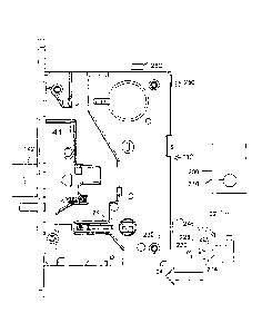
100841 Referring to Fig. 1, an electrical connector key 210 according to the
present invention is
provided to make connection to selected electrical components mounted within
an electronic door
lock 112, which in one or more embodiments is a mortise lock 112 having a
retractable deadbolt 41.
CA 02920552 2016-02-11
-27-
The electrical connector key 210 includes a connector key housing shaped to
engage the electronic
door lock 112. The connector key housing may be formed in two halves 214, 216
(see Fig. 7) that
surround a configurable circuit 218. In the embodiment shown, one end of the
configurable circuit
218 is a card edge connector forming a lock side key connector 220. Within the
connector key
housing 214, 216, the configurable circuit 218 makes connection between
connection points along
the card edge connector and wires forming cable 22. Cable 22 leads to the
external control unit 300,
which sends and/or receives signals passing between electrical components in
the electronic door
lock 112 and the external control unit.
[0085] Fig. 2 shows the electrical connector key 210 inserted into a
corresponding opening 24 in
the lower right corner of the mortise lock 112. The connector key housing 214,
216 is provided
with a notch or groove 226 and a ramp surface 228. As the electrical connector
key 210 is inserted
into opening 24, the ramp surface 228 contacts and slides under a stud 230 in
the interior of the
mortise lock 112. The electrical connector key 210 snaps into a desired
position as the groove 226
reaches the stud 230. Also, as the electrical connector key 210 is inserted,
the card edge connector
forming lock side key connector 220 engages lock connector 36. This connects
the circuit board
218 of the connector key 210 to electrical components within the mortise lock
112. By configuring
the electrical connections provided on the configurable circuit board 218,
different wires within
cable 22 may be connected or not connected.
[0086] Referring to Figs. 7-9, configuration of the key may be achieved simply
by connecting or
not connecting wires 32 in cable 22 to corresponding solder points 234 on key
circuit board 218.
Alternatively, circuit board traces 238 on the key circuit board 218 may be
omitted or added to
CA 02920552 2016-02-11
-28-
achieve configuration. Further, the key circuit board 218 may be provided with
various cross
connections, or with additional electrical components to achieve
configuration.
10087] Additional electronic components may be mounted on the key circuit
board 218 to
identify to circuitry in the lock and or the external control unit 300 what
type of electrical connector
key has been installed and or to signal that a valid and authorized electrical
connector key has been
installed. Such additional components may be as simple as one or more
resistors providing a
resistance that may be detected by electronic circuitry in the lock (and/or
the external control unit)
f
or as complex as an identification chip that provides encrypted communication
with the lock to
identify that an authorized electrical connector key has been installed.
10088] It will be understood from the above description that the electrical
connector key
described permits a single lock mechanism 112, having multiple sensors and/or
actuators to be
prepared in advance and to subsequently be modified to supply different
functions simply by
inserting a different electrical connector key 210 into the opening 24 in the
lock 112. For example,
the lock 112 may be provided with many more sensors than are typically ordered
by a customer.
One customer may desire no sensors on the lock and may only require a basic 12
volt fail-safe type
solenoid lock. In such a lock, when 12 volt power applied is to a wire pair in
cable 22, the lock will
enter the locked state. When power is removed from that wire pair, the lock
will revert to its default
open and unlocked state. This can be achieved by not connecting any sensor
wires 32 through the
configurable circuit 218.
CA 02920552 2016-02-11
-29-
[0089] A second customer may specify a similar 12 volt fail-safe type solenoid
lock except that
the lock must monitor and signal the status of the maximum number of
components within the lock.
Components to be monitored will include the position of the latchbolt 142 (see
Figs. 1, 2 and 5), the
locked or unlocked state of the lock mechanism, and the like. This can be
achieved by connecting
all wires within cable 22 to corresponding connection points on the
configurable circuit 218. The
second customer is provided with a lock mechanism 112 that is identical in all
respects to the lock
provided to the first customer. Only the electrical connector key 210 provided
to the second
customer will be different.
[0090] It will be understood that the first customer will be provided with a
lock mechanism
having more sensors than necessary to provide the functions ordered. This
increases the cost of the
lock provided. However, that cost is offset by the reduction in the number of
different locks
necessary to be stored in inventory and by the advantages derived by rapidly
shipping each
customer's order due to avoiding the time and cost of custom building each
different order. Other
advantages lie in the decreased cost of each lock due to the increase in the
number of identical locks
manufactured. The construction of the locks may be more easily automated. Yet
another advantage
is derived from the fact that the lock mechanism provided to the first
customer (without monitoring
capability) may be upgraded in the field to a more sophisticated lock
mechanism simply by
removing the electrical connector key 210 initially provided and replacing it
with an electrical
connector key having greater monitoring capability.
[0091] In some implementations of the system described above, it may be
desirable for the lock
manufacturer to prepare a limited number of standard lock mechanisms of
increasing complexity
CA 02920552 2016-02-11
-30-
instead of supplying a single identical lock design to all customers with all
possible sensors
installed. This reduces the cost of providing the least commonly needed
sensors to all customers,
when there is little likelihood that such sensors will ever be used or
activated by purchasing a
correspondingly configured electrical connector key. Although this requires
storing more than one
type of lock in inventory, it still allows a reduction in inventory and
manufacturing costs as
compared to holding in inventory all possible configurations for the lock.
Only a small subset of
locks must be manufactured¨for example, a low end model having the most
commonly ordered
sensors, a high end model having all or almost all available sensors and one
or more intermediate
models having some, but not all available sensors. The least complex and least
expensive lock
mechanism 112 can be selected from among the limited subset of standard locks,
provided the
selected lock includes all the monitoring and/or control) functions ordered by
a customer. The
configured electrical connector key 210 having only the ordered features will
be provided with the
selected lock, and total cost is reduced while still meeting the customer's
needs.
[0092] In view of the modular design shown here, it is also possible to store
only a limited subset
of circuit boards containing various combinations of sensors and to quickly
install the appropriate
circuit board having all sensors required, and to match the same with an
appropriately configured
electrical connector key 210that activates only those sensors actually ordered
by the customer. In an
exemplary design, the electrical connector key 210 will be configured at the
factory to provide all
the different available combinations of functions that may be ordered. The
housing 214, 216 may
be permanently glued together or formed as a single molded housing. Only the
less expensive,
CA 02920552 2016-02-11
-31-
differently configured, electrical connector keys need to be stored in
inventory to provide all the
myriad of combinations of functions that are offered to the public.
[0093] Just prior to shipment of a lock ordered with a specified combination
of functions, the
appropriately configured electrical connector key 210 is selected and
installed in the lock 112. The
key 210 is inserted into opening 24 in the lock. The key snaps into place
engaging stud 230 in
groove 226 of the key. As the key is inserted, the card edge connector 220 at
one end of the
configurable circuit 218 (see Fig. 7) engages the lock connector 36 in the
lock 112 (see Fig. 2) and
connects the wires 32 in connector cable 22 to the electronic circuitry board
20 (see Fig. 3) and 20'
(see Fig. 4) within the lock. This enables the specified monitoring and/or
control functions. The
cable 22 is then clipped into cable clips 248, 250 and 252 along the back of
the lock 112.
[00941 The card edge connector 220 forming the lock side key connector
includes multiple
electrical connection points in the form of an array of spaced lands 282
contacted by corresponding
connection points in the lock connector 36. The cable clips 248, 250 and 252
ensure that the cable
22 is held within the mortise provided for the mortise lock 112. The connector
key 210 is also
shaped so that when the connector key 210 is installed, the key does not
project beyond the space
provided in the mortise for the mortise lock 112. The end of
the cable 22 has not been shown,
but may be provided with a connector suitable for connection to the external
control unit receiving
sensor signals and or sending control signals to the actuator circuit 20' to
lock or unlock the lock
112. Alternatively, the wires within cable 22 may be directly soldered to the
external control unit.
- 3 2 -
[0095] Referring to Fig. 3, an example of construction for the circuitry
within the mortise lock is
shown. The circuitry shown may be a circuit board residing inside the mortise
lock and configured to
avoid working components of the lock, and may be an embedded circuit board 20
that fits within a
corresponding recess 12 formed in the cover plate 56 for the mortise lock 112.
A design for such an
embedded circuit board 20 is more fully disclosed in United States Patent No.
8,325,039 and described
further below in reference to Figs. 10A-12C.
[0096] By embedding the circuit board in the cover plate 56, electrical
connections can extend
throughout the mortise lock without interfering with the mechanical components
therein.
Embedded circuit board 20 is provided with multiple sensors 58, 60, 62, 64, 66
and 68. In the
embodiment shown, these sensors are reed switches that are actuated when a
permanent magnet
mounted within a nearby moving mechanical lock components moves towards and
away from the
sensor. Although reed switch sensors are shown, other sensors, such as
mechanical switches, Hall
effect sensors and the like may also be used. Each moving lock component to be
monitored is
provided with a magnet to actuate the associated magnetic reed switch sensor
monitoring that
component. For example, magnet 75 (see Fig. 2) is mounted on spindle hub 42
and moves
whenever an associated handle is rotated to retract the latchbolt 142.
[0097] As may be seen in Fig. 5, sensors 58 and 60 are single throw magnetic
reed switch sensors and
have only two electrical switch connections, while sensors 62, 64, 66 and 68
are double throw switch
sensors and have three electrical switch connections. Additional sensors may
be provided, such as
sensor 72 mounted on actuator circuit board 20' (see Fig. 4). In the
embodiment shown, the
CA 2920552 2018-04-30
CA 02920552 2016-02-11
-33-
lock side key connector 220 is a card edge connector that engages connector 36
mounted on circuit
board 20 for the actuator. The actuator includes control circuitry and a motor
74 that drives a
locking piece 76 to lock and unlock the lock mechanism 112. The actuator
circuit board 20 includes
a connector 78, which may be a card edge connector, engages connector 80 on
embedded circuit
board 20 when the cover plate 56 is installed. In this way, the two circuit
boards 20, 20' are
connected to each other and the connector 36 is positioned to receive the lock
side key connector
220 when the electrical connector key 210 is inserted into the lock 112. The
sensors may be of any
desired type and may be mounted on either of the disclosed circuit boards or
on additional circuit
boards within the lock mechanism.
[0098] Referring to Fig. 5, the lock and method determine if the hub to be
turned by the door
handle is actually locked or unlocked, as measured by a sensor adjacent the
hub and monitored by
the control unit. In the example of the mortise lock, this determines if
tampering has occurred to
disengage the locking member from the hub slot. In the embodiment shown in
Fig. 5, sensor 68 is
used to monitor locking piece 76, which translates in and out of engagement
with a slot 43 in
spindle hub 42 to lock and unlock the lock mechanism 112. Locking piece 76 is
translated by an
actuator assembly including a solenoid or motor, such as motor 74, upon
receiving a signal from a
control unit 300 in an external device. The control unit may be a remote
access control panel or the
controller of an integrated locking device. As shown in Fig. 5, when the
mortise lock cover plate
56 is installed, sensor 68 protrudes into close proximity with magnet 77 below
locking piece 76.
When locking piece 76 is translated to block the rotation of spindle hub 42
(lock is secured), magnet
CA 02920552 2016-02-11
-34-
77 activates sensor 68. Conversely, when locking piece 76 is translated to
permit spindle hub 42 to
rotate (lock is unsecured), sensor 68 is not activated.
100991 Sensor 68 may be a form-C double throw magnetic reed switch sensor with
three electrical
contacts. Sensor 68's output state may be configured per design requirements
to show a "normally
open" or "normally closed" state and the output state will only change due to
the translation of
locking piece 76 as a result of a signal sent from an external control unit.
Accordingly, sensor 68's
output may be monitored by external control unit 300 which can directly detect
an attempt to tamper
with the lock assembly by manually and/or mechanically translating locking
piece 76 to gain entry,
thereby triggering an external alarm 310 in the control unit. In normal
operation, external control
unit 300 sends a signal to activate the solenoid or motor to translate locking
piece 76. If the control
unit 300 has not sent a signal to activate the solenoid or motor, a change in
output state of sensor 68
will trigger an external alarm indicating that tampering has occurred.
Additionally, the circuit
containing sensor 68 may be connected in series with a sensor detecting the
presence of electrical
connector key 210 in the lock assembly. The sensor detecting the presence of
connector key 210
may be integrated within external control unit 300, or integrated within the
lock assembly 112 or
connector key 210 itself. If electrical connector key 210 is removed from the
lock assembly, the
control unit 300 will detect a change in output state from the electrical
connector key sensor and/or
sensor 68, again triggering an external alarm. This tamper-detection circuitry
may be designed in
series with other sensors/switches, such as a sensor 410 that detects the
removal of a covering trim
component, integrated reader, keypad, escutcheon or other external lock member
400, as shown in
Fig. 12B, in accordance with the object of the present invention.
CA 02920552 2016-02-11
-35-
[00100] The present invention also provides a lock and method to detect
tampering with the
latchbolt or deadbolt locking mechanism. As further shown in Fig. 5, each of
sensors 58 and 60
may be a form-A single throw magnetic reed switch sensor sharing a common
input, and are jointly
used to monitor deadbolt 41. As shown in Figs. 6A-6C, deadbolt 41 may be
translated back and
forth in direction 39 by an actuator assembly including a solenoid or motor
74', upon receiving a
signal from an external control unit 300. Alternatively, deadbolt 41 may be
mechanically actuated,
such as by the rotation of a key, rotation of a thumb turn, or through linkage
driven by the latchbolt.
It is desirable to have the ability to detect both a projected (secured) and
retracted (unsecured)
deadbolt position for maximum tamper prevention. As may be seen in Fig. 5,
when the mortise lock
cover plate 56 is installed, sensors 58, 60 protrude into close proximity with
magnet 95 which is
mounted on deadbolt 41. As shown in Figs. 6A-6B, sensors 58, 60 swap output
states as the
deadbolt is projected or retracted. As depicted in Fig. 6A, when deadbolt 41
is retracted (unsecure),
magnet 95 activates sensor 60 and sensor 58 is not activated. Conversely, when
deadbolt 41 is
projected (secure), magnet 95 activates sensor 58 and sensor 60 is not
activated, as shown in Fig.
6B.
[00101] The output state of sensors 58, 60 may be configured per design
requirements to show a
"normally open" or "normally closed" state, and the output of sensor 58, 60
may be simultaneously
monitored by external control unit 300 which can detect an attempt to tamper
with the lock
assembly by manually and/or mechanically translate deadbolt 41 to gain entry.
If the external
control unit 300 has not previously sent a command signal to activate the
solenoid or motor 74' to
translate deadbolt 41 into a retracted (unsecured) position, the external
control unit will sense a
CA 02920552 2016-02-11
-36-
change in output state of either sensor 58, 60 and will trigger an external
alarm 310 indicating that
tampering has occurred.
[00102] Moreover, it is understood that under normal operation, magnet 95 can
only be present at
one sensor or the other (deadbolt projected or retracted). Tampering may be
attempted by applying
a magnetic field on the exterior of the lock. Therefore, if both sensors 58,
60 activate in the
presence of a magnetic field, it is an indication that a magnetic field is
being applied from an
external source, such as magnet 96, as shown in Fig. 6B. In such a scenario,
by monitoring the
outputs of sensors 58, 60 simultaneously, a magnetic tamper can again be
detected by external
control unit 300, triggering an alarm.
[00103] The deadbolt monitoring system may also detect a deadbolt position
somewhere in
between a projected (secured) and retracted (unsecured) position, which may
also indicate
tampering. As shown in Fig. 6C, when deadbolt 41 is between these positions,
magnet 95 is not
present at either sensor 58 or sensor 60 and neither sensor is activated, and
there is the simultaneous
absence of a signal from both. If this condition persists for a predetermined
period of time as
monitored by external control unit 300, as set per design requirements, an
external alarm will be
triggered which signals to the user that a potential vulnerability exists in
the lock assembly 112.
[00104] Figs. 10A-F show those embodiments of the invention included an
embedded circuit
board 20. In these embodiments, at least one interior surface 11, 13 of a
locking device housing 10
is provided with a channel 12 that corresponds to the shape, size and
thickness of a corresponding
printed circuit board (PCB) 20. In one or more embodiments, this channel 12 is
a recessed channel
CA 02920552 2016-02-11
-37-
residing within a thickness of a housing side. The interior surfaces of the
locking device housing 10
may include any interior surface within the housing 10 including, but not
limited to, a first interior
surface 11 of a first side 18 of the housing, a second interior surface 13 of
a second side 19 of the
housing, and so on. At least two or more of these interior surfaces of their
respective sides may
oppose one another, e.g., interior surface 11 of side 18 opposes interior
surface 13 of side 19, with
the mechanical working components of the lock residing there-between.
1001051 Both the recessed channel 12 and the PCB 20 have corresponding shapes
and sizes
configured so that they avoid interference with mechanical working components
of the locking
device. Mechanical working components include latch bolts, dead bolts,
cylinder locking
mechanisms, blocking mechanisms, hubs, cams, levers, and the like. These
shapes and sizes of the
recessed channel 12 and PCB 20 also avoid interference with any openings in
the housing 10
including, but not limited to, lock cylinder openings, screw or bolt openings,
spindle openings,
threaded openings, blocking openings, and the like.
[00106] In one or more embodiments, the first 18 or second 19 sides alone may
be provided with a
PCB 20 (either embedded therein or residing on a surface thereof), or both the
first and second sides
18, 19 of the locking device housing 10 each may be provided with one or more
PCBs 20 in
accordance with the invention. Multiple embedded PCBs 20a, 20b, 20c may be
provided in or on
the PCB. Alternatively, a single continuous circuit board embedded within or
residing on an interior
surface of one or more of the sides of the locking device housing 10, as shown
in Figs. 10A-F. The
single continuous PCB is configured with a shape and thickness that does not
interfere with any
working or moving components inside the mechanical lock. For instance,
referring to the drawings,
CA 02920552 2016-02-11
-38-
the PCB may have a shape that carries electrical wiring on the circuit board
between the top 16 and
bottom 17 of thc lock and simultaneously between the left and right lateral
sides 18, 19 of the lock,
In one or more embodiments this shape may be a sinusoidal shape that covers
over a distance of
more than 50%, and even more than 60%, of the diagonal distance across the
surface area of the
side in which such sinusoidal shaped embedded PCB resides.
[00107] The PCBs 20 provide electrical wiring connections between the multiple
circuit boards
from top 16 to bottom 17 and left to right lateral sides 18, 19 of the lock.
The circuit boards
residing on or embedded within these multiple interior surfaces may be
electrically connected to one
another via wiring extending from one side of the housing 10 to the other side
of the housing 10.
This wiring may reside inside the locking device housing 10 (e.g., it may be
contained within
another circuit board), or it may reside outside the locking device housing
and electrically connect
the PCBs to one another through the openings 30 residing at the bottom of the
recessed channels 12.
[00108] Referring to Figs. 10E-F, the exposed surface of channel 12 may
optionally have one or
more openings 30 traversing there-through. These openings 30 also allow
electrical circuitry outside
the lock to be connected via wiring to an electrical connector that may reside
on the backside of the
PCB in locations corresponding to the openings 30, A ground plate may also
reside on the backside
of the PCB along with the one or more electrical connector(s) or as a stand
alone feature.
[00109] As shown in the drawings, the PCBs may have a thickness substantially
equivalent to the
thickness or depth of the corresponding recessed channel into which such PCB
is to be embedded.
In this manner, once embedded the PCB(s) minimize, or all together avoid,
modifications to and/or
CA 02920552 2016-02-11
-39-
rearrangements of existing mechanical working components of the locking
device, avoid moving
parts within the locking device, and optimize the positioning of sensors,
magnets and/or actuators
within the locking device as discussed further below. Optionally, in locations
that do not interfere
with lock openings and/or working components multi-surface mount technology
may be employed
by mounting one or more additional circuit boards on top of the embedded PCB
to provide the
electrified lock with increased processing power. These additional surface
mounted circuit boards
extend upward from a surface of the embedded PCB into the locking device (may
be parallel or
perpendicular to the embedded PCB).
[00110] Either before or after the PCB is embedded inside the housing side,
various electrical
components may be surface mounted to the PCB in strategic locations across the
board. In one or
more embodiments, the working components of the mechanical lock may be
provided with magnets
55 at various locations. These magnets 55 may reside on a surface of the
working components, be
inset into the surface of the working component, or even be imbedded inside
the working
component itself. The plurality of magnets 55 residing on the lock's working
components provides
the ability to monitor the working components at multiple locations to detect
multiple positions,
including opened and closed positions, of such working components, as opposed
to conventional
methods and approaches that only allow the monitoring and detection of opened
and closed
positions due to wire routing, size, and space constraints.
[00111] The PCB(s) of the invention may be provided with one or more sensors
50 at various
locations across the PCB. A bypass capacitor 52 may be connected to each
sensor 50 to eliminate
system noise and avoid sensor oscillations. The sensors attached to the PCB
include, but are not
CA 02920552 2016-02-11
-40-
limited to, non-contact sensors, analogue transducers, hall sensors,
electrical switches, reed
switches, and the like. These sensors 50 are attached at positions
corresponding to the magnets on
the mechanical working components of the lock for sensing the positions of
these various
mechanical lock components. As the working component with its magnet moves or
rotates, the
magnet is brought into or out of close proximity with a sensor mounted on the
PCB, thereby
enabling monitoring of the door and/or lock movement to detect opening and
closing of the door,
tampering with and/or vandalism to the lock or door, actuation of levers or
bolts, and the like.
[00112] In some embodiments, one or more sensor(s) 51 may be raised away from
the surface of
the PCB, such that, the raised sensor extends toward the other side of the
housing for sensing
magnets residing at or near this other side of the housing. As an alternative,
an embedded PCB may
reside in this other side of the housing and have one or more surface mounted
sensors for detecting
a magnet near this side, whereby the embedded PCBs on opposing sides may be
connected to one
another via electrical wiring.
[00113] Other electrical components that may be mounted to the PCBs of the
invention include
sensors 54 that do not require a magnet for triggering. These sensors may
include, but are not
limited to, mechanical micro-switches, a Magnasphere sensor, push buttons,
optical sensors, and the
like. An actuator 61 may also be attached to the housing side in which the
embedded PCB resides
to drive the lock components to lock and/or unlock the lock. The actuator 61
is attached to the
housing side in a location that is in close proximity to the PCB so that the
actuator 61 is electrically
powered by the PCB via wiring and a connector. As an alternative, the actuator
may be directly
assembled to the PCB. Actuators suitable for use in the various embodiments of
the invention
CA 02920552 2016-02-11
-41-
include, but are not limited to, solenoids, motors, brush DC motors, stepper
motors, piezo motors,
shape memory actuators, and the like. If increased electrical current is
required, such as with the
use of a solenoid actuator, traces may be routed through a middle PCB layer or
the board may be
conformally coated with an insulation layer to protect external circuits and
components.
[00114] The PCBs may also be provided with one or more surface mount
connectors 70 having
inputs for electrical connection to the actuator 61. Other electrical
components surface mounted
onto the surface of the PCB that resides inside the lock include, but are not
limited to, an
accelerometer, temperature sensors, heating components, and the like. An
accelerometer enables
the measuring or impact on the door to detect if the door is being closed, if
the door is being
impacted or hit (e.g., someone vandalizing the door), and the like.
Temperature sensors enable the
measuring of the temperature inside the lock. A heating component provides
heat inside the lock to
control the internal lock temperature to prevent freezing and maintaining the
workability of the
internal mechanical lock components.
[00115] A signal output device 81 may be connected to the PCB. This signal
output device may
be a controller board as shown in Fig. 10B and 10D, or it may be a wire
harness as shown in Fig.
11B. The signal output device 81 is an electronic module on the PCB that
intakes the electrical
signal outputs from the various electronic components residing on or in
electrical communication
with the PCB 20 and converts these inputs into a readable, digital output
signal. For instance, a
WIFI or communications module (e.g., Ethernet, bluetooth, and the like) may be
assembled into the
device 81 mounted on the PCB to link the PCB to a centralized lock control
system. As such, this
WIFI or communications module is embedded inside the lock.
CA 02920552 2016-02-11
-42-
[00116] At various locations across the PCBs, selected ones or each of the
PCBs may be provided
with a number of openings 90 in the PCB. These openings 90 may reside in
locations on the PCB
corresponding to locations of working components of the lock, in locations
corresponding to
positions where external devices may be inserted into the lock, in locations
corresponding to where
screw 92 may be inserted to secure the housing side to the rest of the lock
housing, and the like.
[00117] Whether
one or more PCBs are embedded inside a lock device housing, the
invention enables the utilization of the embedded PCB(s) for all electronic
functions within a
locking mechanism to increase performance capabilities including, but not
limited to, precise
sensing, actuation, circuit routing, efficient electrical connectivity, signal
conditioning (e.g., AC
rectification), communications (e.g., WiFi, bluetooth, etc.), logic control,
micro-processing which
can condition the signals for input or output, signaling (e.g., LED, status
indicators, etc.), and
standardized connectorization to external circuits. The embedded PCBs of the
invention may also
be equipped with wireless or cellular circuits that may connect to an external
antenna.
[00118] Again, the shape, size and length of each PCB of the invention, or
combinations of PCBs,
allow electrical wiring to be provided from one end of the lock to another end
of the lock (e.g., from
the bottom to the top of the lock). In one or more embodiments, the PCB(s) is
provided over a
diagonal distance across the lock from top to bottom, and vice versa, whereby
multiple sensors are
strategically positioned on the PCB to sense the magnets residing in or on the
mechanical working
components to detect the movement thereof. As such, the PCBs provide all of
the wiring within the
lock housing and simultaneously provide the positioning for the various
sensors within the lock that
are used to detect motion of the mechanical lock components. This allows the
circuitry to determine
CA 02920552 2016-02-11
-43-
when the lock is open, when the dead bolt 41 has been operated, when the dead
bolt 41 is in motion,
and the like.
[00119] By embedding PCBs within an internal surface of a locking device
housing 10, the various
embodiments of the invention are suitable for use with those locking devices
having constrained
real estate. The invention converts a locking device having constrained real
estate from a strictly
mechanical locking device into an electrified lock having capabilities for
digital monitoring and
electronic actuation directly inside the locking device itself. These locking
devices with constrained
real estate may include existing locking devices having more compact designs,
existing mechanical
locking devices having increased and/or improved technological advances
residing inside the
locking that consume an increased or substantial portion of the valuable real
estate within the lock,
and even future lock designs configured with constrained real estate.
[00120] While not meant to limit the invention, one or more embodiments of the
invention are
suitable for use with locking device housings 10 that encase the mechanical
lock device
components. For instance, one such suitable lock encasing is a mortise lock
housing 110 as shown
in Figs. 12A-C. A mortise lock housing 110 includes a lateral side 119 being a
cover plate and a
casing portion. The casing portion of the mortise lock housing includes top
160 and bottom 170
walls, a back wall 140 and a lateral sidewall 118 that opposes the cover plate
lateral side 119 when
the housing is assembled. A front plate 128 resides opposite the back wall 140
and between sides
118, 119. Again, in one or more embodiments, an interior surface 1 1 1 of the
first lateral sidewall
118 alone, an interior surface 113 of the cover plate 119 alone, or interior
surfaces 111, 113 of both
CA 02920552 2016-02-11
-44-
the sidewall 118 and the cover plate 119 of the mortise housing 110 may be
provided with one or
more embedded PCBs 120 in accordance with the invention.
[00121] Referring to Fig. 12C, a single embedded PCB 20 assembly of the
invention is shown
whereby the PCB 20 is configured with a shape, size and thickness that does
not interfere with the =
positioning of the lock's working components residing inside the housing 110
and allows the PCB to
pass around the various openings in the mortise lock. These working components
residing inside
the mortise lock include components connected to handle actuators to throw the
dead bolt 41 and
the various pivots supported by the cover plate for components that move
within the mortise lock.
For instance, the working components may include, but are not limited to, a
control hub 132,
spindle hubs 134, 136, spindle openings 138, a latch bolt 142 having a latch
bolt tail 140, a shaft
150 turned by a rotatable element 148, a latch retract lever 162, a lock
cylinder opening that may
rotate the control hub 132 and the like.
[00122] In the various embodiments of the invention, one or more, or even all,
of these working
components of the mortise lock may be provided with one or more magnets 55 on
or inserted into a
surface thereof. With the PCB 20 configured to avoid the openings in the
mortise lock and these
working components, while still residing in close proximity thereto, the
sensors 50 are strategically
positioned on a surface of the PCB so that the sensors 50 are in close
proximity to the various
magnets 55 for detecting and monitoring motion of these working components of
the lock.
[00123] Some of the sensors 50 may reside on the PCB while other sensors 51
may be connected
with leads to allow the sensor 51 to stand up and away from the surface of the
PCB. In this manner,
CA 02920552 2016-02-11
-45-
the sensor 51 is projected into the lock mechanism toward the opposing
sidewall to detect magnets
55 residing on locking components that reside adjacent or near this opposing
sidewall. For instance,
referring to Fig. 12C, the two spindle hubs 134, 136 each have a corresponding
oval comprising a
magnet 55. The spindle hub 136 closest to the PCB has a corresponding sensor
50 mounted directly
on the surface of the PCB, while the spindle hub 134 located farthest from the
PCB is sensed by a
sensor 51 that is raised off the surface of the PCB and resides within the
mechanical lock.
[00124] Once the interior surface of the lateral sidewall 118, the cover plate
119, or both the lateral
sidewall 118 and the cover plate 119, have been provided with one or more
embedded PCB(s) in
accordance with the invention, the now electrified mortise lock is secured
within a mortise recess
260 residing between front 214 and back 212 surfaces of a door 200.
Accordingly, the various
embodiments of the invention provide for the easy and efficient conversion of
a conventional
mortise lock into an electrified mortise lock having electronic capabilities,
particularly, digital
monitoring and electronic actuation inside the locking device itself. In one
or more embodiments,
the electrified mortise lock of the invention includes one or more PCBs
configured to carry wiring
from one portion of the mortise lock to another portion of the lock for the
electrical connection of a
variety of components residing on the PCB to provide the lock with hall effect
and/or reed sensing,
solenoid actuation for electrified locking and/or unlocking the mortise lock,
minimal mechanical
modifications, embedded magnets, on-board processing and/or communications
linked to a
centralized lock control system, and the like.
[00125] It should be appreciated that the housing side containing the embedded
PCB may be
configured as a universal lock housing side (e.g., a universal lock housing
cover plate) for
CA 02920552 2016-02-11
-46-
installation in existing lock devices having no electronic components. In this
manner, a
conventional non-electric lock having reduced cost, high volume, lock
components may be
converted into an electrified lock that has electrical monitoring and
actuation capabilities.
[00126] It should be appreciated that in one or more embodiments of the
invention the PCB(s) may
be secured directly inside other types of housed locks including, for example,
a cylindrical lock. In
this aspect, an internal surface within the cylindrical lock (e.g., the
cylindrical outside of the lock)
may be provided with a recessed/routed out depression for accommodating an
embedded PCB.
Alternatively, an internal surface of the cylindrical lock may be provided
with a mount for securing
the PCB inside the lock. In either aspect, both the channel and the PCB are
configured to avoid any
openings and/or working components within the lock. The PCB is secured inside
the channel so
that the conventional cylindrical lock is converted from a non-electrified
lock to an electrified
cylindrical lock. For instance, the electrified cylindrical lock may include
slotted mounts, reed
sensing, an on-board bridge rectified solenoid circuit, a motor circuit, an
integrated earth ground, a
common wire harness connection and the like.
[00127] The PCBs
may be used in a variety of electronically actuated access-control devices
100 including, but not limited to, exit devices, electronic door strikes, door
closers, door operators,
cylindrical locks, tubular locks, auxiliary locks, deadbolts, and the like.
For instance, one or more
PCB may be embedded or provided within the rail of an exit device, embedded
within a plate of the
door strike or closer, and the like. Additionally, the PCBs may be used in a
variety of electronically
actuated access-control devices 100 that employ the use of various access user
recognition systems
including, but not limited to, a key, a password, a card (e.g., the lock would
include a slot for
- 47 -
insertion of a card directly into a reader within the lock), magnetic
components, a keypad, a
fingerprint recognition device, an RF card reader, a remote controller
recognition system, and the
like.
[00128] While still not deviating from the novel concepts of the invention of
having one or more
PCBs residing inside a locking device itself, rather than embedding the board
inside a side of the
locking device housing, mounts or harnesses may be secured to an internal
surface of the locking
device housing. These mounts or harnesses may reside in locations that will
not interfere either with
the various lock openings or with the working components of the lock. The PCBs
may then be
embedded within the mount(s) or harness(es) residing on an interior surface of
the housing so that the
PCBs reside inside the locking device housing itself. Optionally, one or more
of the working
components inside the lock may be mechanically machined to remove a portion of
the working
component thickness so as to prevent and/or avoid contact with the PCB mounted
onto the internal
surface of such housing side.
[00129] Referring to the actuator assembly shown in Fig. 4, the solenoid
operation emulates using
an energy efficient motor 74. The associated circuitry is operable with both
12 volts and 24 volts
and may be switch selectable to emulate either "fail safe" (default unlocked)
or "fail secure"
(default locked). The actuator and associated circuitry may be of any type
known to those of skill
in the art. By selecting the appropriate actuator and control circuitry, the
lock can be operated by
and/or connected to any type of external control unit to provide lock control
and door lock
monitoring. Any type of actuator and circuitry may be used.
CA 2920552 2018-04-30
- 4 8 -
[00130] Those of skill in this art will note that the cost of manufacturing
the different
configurations for the electrical connector key is relatively low as compared
to the cost of
constructing the lock mechanism and its sensors. It is desirable to be able to
sell a low-end lock
mechanism with few sensors at a lower price than a higher end lock mechanism
having many
more sensors. As such, it may be desirable for the manufacturer to ensure that
any electrical
connector key inserted into the lock is an authorized electrical connector key
in order to prevent
low end devices from being ordered at a low price and upgraded at low expense
with an
unauthorized electrical connector key that has been reconfigured to activate
all sensors installed
in the lock mechanism. As previously noted, this can be achieved by placing
circuitry in the
electrical connector key, such as an identification chip that provides
encrypted communication
with a microprocessor or other digital component in the lock to identify to
the lock or to the
external control unit that an authorized electrical connector key has been
installed.
[001311 For example, a simple 3-pin device such as an Atmel AT88SA1 OHS-TSU-T
needing
only power ground and a serial data connection can be installed on the key
circuit board 218 to
provide digital confirmation to the lock that the installed electrical
connector key is authorized.
Other simpler methods of providing such confirmation of an authorized
electrical connector key
are also known to the art.
CA 2920552 2018-04-30
CA 02920552 2016-02-11
-49-
[00132] When complex digital encryption and handshaking techniques are used,
they may require
a short time period during which calculations are made to provide the
necessary digital confirmation
of authorized status. If the electrical connector key fails to pass
authorization testing, the circuitry
in the lock mechanism will refuse to operate the actuator installed and or
refuse to pass sensor
signals ¨ depending on the selected design for the lock circuitry. A delay
before actuation of the
lock, however, is undesirable. Accordingly, in an exemplary design, an
authorization bit is stored
by the lock mechanism control circuitry within the lock and authorization
testing is completed by
the lock mechanism control circuitry after the lock completes an actuation
cycle, not before.
[00133] The authorization bit is initially set to "authorized" status. The
lock mechanism control
circuitry checks the authorization bit before driving the actuator to operate
the lock. This allows
one or more initial cycles of the lock to be performed successfully,
regardless of the true authorized
status of the electrical connector key and provides the advantage of avoiding
any delay for
authorization testing. When the lock has a suitable time period to complete
the authorization
testing, the authorization bit is then set to "unauthorized" status and
subsequent operation of the
lock is prevented.
[00134] It will be understood that the electrical connector key may be adapted
to provide many
different types of configured interconnections between selected components
within the electronic
door lock and the external control unit. One such configured interconnection
is a simple
"connected" or "not connected" configuration. The external control unit may
simply not be able to
receive sensor signals (or not send signals to selected lock components.)
Another configuration
may involve rerouting signals from the lock back to the lock for subsequent
processing. One lock
CA 02920552 2016-02-11
-50-
mechanism may be send "raw" sensor signals to the external control unit.
Another lock mechanism
may have sophisticated electrical processing capabilities and may use the same
"raw" sensor signal
internally, in combination with other sensor signals to provide a processed
output signal to the
external control unit.
1001351 Further, the electrical connector key may incorporate additional
electronic components to
provide additional functions to the lock. A WiFi transmitter/receiver and
antenna may be added.
Alternatively, the electrical connector key may be provided with a numbered ID
chip allowing the
lock to be identified by the external control unit it is connected to. Many
other interconnection
schemes and additional functions for the electrical connector key will be
apparent to those of skill in
this art.
[00136] Another aspect of the invention resides in a system comprising
multiple differently
configured electrical connector keys of the type described above in
combination with one or more
different lock mechanisms capable of receiving a selected one of the
differently configured
electrical connector keys. Each different lock mechanism has a different
selection of electrical
components therein. The selected one of the differently configured electrical
connector keys is
paired with a selected one of the one or more different lock mechanisms. The
selected connector
key and the selected one of the door lock mechanisms define a complete
electronic lock ready for
connection to the external control unit and provides a specific selected
interconnection between
selected electrical components available in the selected one of the door lock
mechanisms and
circuitry in the external control unit.
CA 02920552 2016-02-11
-51-
[00137] It will also be understood that another aspect of the invention is the
method of providing
an electronic door lock having desired functionality in which multiple
differently configured
electrical connector keys of the type described above are provided and one or
more different door
lock mechanisms capable of receiving the electrical connector keys are
provided. One of the
provided one or more different door lock mechanisms is selected and one of the
differently
configured electrical connector keys is also selected. The combination of the
selected electrical
connector key and the selected door lock mechanisms provides the desired
functions for the
complete electronic door lock when the electrical connector key is inserted
into the selected
electronic door lock and connected to the external control unit.
[00138] Therefore, the present invention achieves one or more of the objects
described above. The
configurable electrical connector key for connecting an electronic door lock
to an external control
unit, such as a lock monitoring or control system, includes a connector key
housing shaped to
engage the electronic door lock and a configurable circuit mounted within the
connector key
housing that makes a configured interconnection between selected components
within the door lock
and the external control unit. The combination of an electrical connector key
and an electronic door
lock and a system and method includes multiple differently configured
electrical connector keys and
one or more standardized electronic door locks to allow selected sensors and
functions of the door
lock to be enabled by selecting an appropriately configured electrical
connector key.
[00139] While the present invention has been particularly described, in
conjunction with a specific
preferred embodiment, it is evident that many alternatives, modifications and
variations will be
apparent to those skilled in the art in light of the foregoing description. It
is therefore contemplated
CA 02920552 2016-02-11
-52-
that the appended claims will embrace any such alternatives, modifications and
variations as falling
within the true scope and spirit of the present invention.