Note: Descriptions are shown in the official language in which they were submitted.
CA 02920576 2016-02-05
WO 2015/020956
PCT/US2014/049595
TITLE OF THE INVENTION
Vertebral Endplate Apparatus and Method
Technical Field
[0001] The preferred embodiments relate to relate to spinal surgical
apparatus and
methodology and more particularly to accessing spinal biological materials via
a
vertebral endplate.
Background Art
[0002] Spinal pain and more particularly pain in connection with spinal
discs may
occur from both acute and chronic conditions as well as with deterioration
from disease
and age. Such disc issues arise most commonly in the spinal lumbar region,
second
most commonly in the cervical region, and finally least commonly in the
thoracic
region. Treatment for such issues may include medication (e.g., anti-
inflammatories,
steroids, cortisone, and pain therapies) as well as surgery. Contemporary
surgeries are
typically directed at reducing pain in association with a damaged or diseased
disc, such
as by reducing pressure in the area, removing damaged portions of the disc,
replacing
the disk with an artificial counterpart, and/or bracing the spine in the area
of the
suspected disc through the use of spinal fusion, that is, fusing together the
vertebrae that
are located above and below the disc(s) at issue. Such approaches have some
measure
of success in some patients, but also carry considerable cost, risk of
complications, and
in some instances limited or no pain relief
[0003] By
way of further context, Figure 1 illustrates a simplified view of two spinal
vertebrae, where the spine is generally comprised of numerous vertebrae that
span
downward from the neck (or cervical) region, through the thoracic region and
the
lumbar region, to the sacrum. The preferred embodiments may have preferred
application to surgery in the lumbar region, but such embodiments, or
alternative
preferred embodiments, may prove beneficial for other regions of the spine
(i.e., cervical; thoracic). The additional detail of Figure 1 illustrates that
each pair of
vertebrae are separated by an intervertebral disc. More particularly, each
vertebra has
1
CA 02920576 2016-02-05
WO 2015/020956
PCT/US2014/049595
an upper and lower surface referred to as an endplate, and the disc is
therefore located
between the upper endplate of one vertebra and the lower endplate of a
neighboring
vertebra.
[0004] Given
the preceding, the preferred embodiments relate to repairing injury,
damage, or deterioration to a spinal disc and in relation to the endplate
either above it or
below it (or both), as further described below. Numerous benefits will be
appreciated
by one skilled in the art, given an understanding of that discussion and with
additional
observations to follow.
2
CA 02920576 2016-02-05
WO 2015/020956
PCT/US2014/049595
Disclosure of Invention
[0006] In one preferred embodiment, there is a surgical apparatus for use
in
connection with spinal surgery. The apparatus comprises a first portion having
a tip
for first following along an insertion axis, for entering into a spinal disc,
and for
penetrating an endplate of a vertebra adjacent the spinal disc. The apparatus
further
comprises a second portion, adjacent the first portion, for remaining along
the insertion
axis as the tip of the first portion extends to penetrate the endplate of the
vertebra
adjacent the disc.
[0007] Other aspects and methods are described and claimed.
3
CA 02920576 2016-02-05
WO 2015/020956
PCT/US2014/049595
Brief Description of Drawings
[0009] The invention will be described in detail below by referring to
the
accompanying drawings:
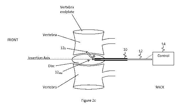
[0010] Figure 1 illustrates a simplified view of two spinal vertebrae.
[0011] Figures 2a-2c illustrate the preferred embodiments in connection
with the
spinal items shown and described in connection with Figure 1.
[0012] Figure 2d illustrates the preferred embodiment of Figures 2a-2c
but without
the spinal items for sake of discussion.
[0013] Figure 3 illustrates a generally cross-sectional view of an
additional preferred
embodiment, consistent with the preceding and including an anulus entry
device.
4
CA 02920576 2016-02-05
WO 2015/020956
PCT/US2014/049595
Description of Embodiments
[0015]
Figure 1 was discussed in the Background Art section of this document and
the reader is assumed to be familiar with the concepts of that Figure and
discussion.
[0016]
Figures 2a-2c illustrate preferred embodiments in connection with the spinal
items shown and described in connection with Figure 1. In Figure 2a, a pathway
is
introduced into the disc by way of an apparatus 10, which is shown in cross-
section and
may be a cannula, as is known in the medical arts. Cannula placement is well
known
and may involve the use of related apparatus and steps, including percutaneous
entry, a
guide wire, and dilitation. In various preferred embodiments and based on
various
considerations including location of the spinal treatment and the underlying
medical
condition, preferred embodiment methods for locating the apparatus 10 for
treatment
according to this document may include posterior insertion, posterior lateral
(e.g., 30 to
60 degrees off midline) insertion, direct lateral insertion, or anterior
insertion.
[0017] The
inner diameter of the cannula is preferably in a range of 1.0 to 3.0
millimeters, and it provides a pathway cavity through which apparatus and
fluids may
pass. In this regard and more pertinent to the preferred embodiments, the
pathway
created by the apparatus 10 permits placement along an insertion axis of an
additional
penetrating device 12, which in Figure 2a is shown prior to such insertion and
in Figure
2b is shown inserted through the apparatus 10. In a preferred embodiment, the
penetrating device 12 may be formed, or may include or have at surfaces, of
various
materials, including, as examples, medical grade steel, titanium, cobalt
chromium, or
nitinol. Additionally, in Figure 2b, therefore, a leading tip 12T (labeled in
Figure 2a, by
example, to simplify other drawings), of the penetrating device 12, is placed
through the
inner pathway of the apparatus 10 so that ultimately the tip 12T extends
beyond that
pathway and into the interior of the disc. Note also that for certain
locations of the
spine (e.g., sacral or lower lumbar), the apparatus 10 may have a shape that
is curved, in
whole or part.
[0018] A
control unit 14 is also shown in Figures 2b and 2c, in connection with the
penetrating device 12. The control unit 14 includes any manner of electrical
and/or
5
CA 02920576 2016-02-05
WO 2015/020956
PCT/US2014/049595
mechanical guidance and signal control so as to effect the steps described in
this
document. In this regard, the combination of the penetrating device 12 and the
control
unit 14 allow an additional key aspect, as illustrated in Figure 2c.
Specifically, in
Figure 2c, and once the penetrating device 12 has its tip 12T located in the
disc, then
either through mechanical and/or electrical manipulation, the tip 12T of the
penetrating
device 12 is operated to shift, either upward or downward, at an angle 0 from
the
longitudinal axis of the remainder of the penetrating device 12 that is still
positioned
through the apparatus 10. Indeed, by way of example, note that the penetrating
device
12 is shown in all three Figures 2a-2c to include a pivoting mechanism 12pm
near its tip
12T (both labeled in Figure 2c), so that once the device 12 is inserted as
shown in
Figures 2b and 2c, its tip 12T may pivot about the mechanism 12pm so as to
achieve the
angular displacement of 0 as shown in Figure 2c. By pivoting in this manner,
the tip
12T of the penetrating device 12 makes contact with the adjacent vertebral
endplate,
which in the example of Figure 2c is the endplate above the disc. Note also
while not
shown, the pivoting mechanism 12pm, as well as other aspects included with the
penetrating device 12 and/or the control unit 14, are further operational for
controlling
the depth of penetration of the tip 12T into both the disc and the vertebral
endplate.
[0019]
Various manners of implementing the pivoting mechanism 12pm are
contemplated within the inventive scope. For example, while not shown, a
gearing
mechanism may be included at the point, to include a worm gear and/or
ratcheting teeth,
so as to change the angular displacement of 0. Moreover, in one preferred
embodiment
the displacement of 0 may be continuously variable, while in another it may
have fixed
selectable values or increments. Note also that the pivoting mechanism 12pm is
only by
way of example, where other manners may be implemented so as to allow a tip or
extension to reach in a direction away from either a lateral orientation or
away from the
insertion axis of the apparatus and toward a vertebral endplate.
[0020]
Further in connection with Figure 2c, note that the tip 12T, extending away
from the insertion axis, includes a sufficient apparatus so as to penetrate
the endplate
and thereby extend within the interior of the vertebra. This apparatus may
include, for
example, an awl or a drill, where the former by its shape and with applied
force may be
6
CA 02920576 2016-02-05
WO 2015/020956
PCT/US2014/049595
sufficient for penetration, and where the latter for example might be operated
in
connection with the control unit 14 to thereby accomplish stimulation to cause
rotation
of the drill, and hence the tip 12T, so as to accomplish a rotational assist
with such
penetration. Other approaches also are contemplated within the inventive
scope,
including a punch or a cut. Moreover, differing preferred embodiments use a
material
and/or structure selected for the tip 12T so as to facilitate its intended
functionality of
penetrating a vertebral endplate. For example, the tip 12T may comprise a
hardened
material, a diamond coating, and/or may be constructed using atomic
sharpening.
[0021] Given
the preceding, the pivoting (or direction changing) functionality of the
tip 12T of the penetrating device 12, and the penetration of the vertebral
endplate, allow
one or more holes (i.e., apertures) to be formed into the disc endplate. These
holes will
facilitate treatments that may be akin to what is known as microfracture
surgery, which
is typically performed in connection with treating damaged cartilage in
arthroscopic
knee surgery. In such microfracture surgery, a tool is used to create small
holes in bone
adjacent the knee cartilage and to penetrate to a sufficient depth to reach a
blood supply
and cells (e.g. including stem cells). These biological materials may then get
to the
surface layer and stimulate nearby cartilage growth. Due to the
maneuverability in the
location and structure of the knee, a linear tool may be used to create such
holes. In
contrast, however, the preferred embodiments are directed to usages in
connection with
the spine, where physical manipulation of a linear tool may not be feasible,
particularly
in the lumbar region. Instead, the use of a preferred embodiment as depicted
in Figures
2a-2c, where the tip 12T may be directed in a direction that is not co-linear
with the
length of the tool that is inserted into the back region, thereby facilitates
placement of
the hole-causing tip into the vertebral endplate. With such holes, proper
extraction of
bone marrow elements, including stem cells, and usage of attendant biologics,
may be
implemented so as to have certain chemistries move into or be available in the
areas of
the intervertebral disc. As a result, it is projected that such chemistries
may assist with
healing and growth in the area so as to augment or supersede existing
treatment
modalities.
7
CA 02920576 2016-02-05
WO 2015/020956
PCT/US2014/049595
[0022]
Figure 2d again illustrates the penetrating device 12, but without the spinal
elements so as to simplify the drawing and for purposes of some additional
observations. Having described the preferred embodiment functionality of
penetrating
a vertebral endplate, more generally one skilled in the art should now
recognize that the
penetrating device includes two portions, a first portion 12pi that is first
inserted into the
skin along the insertion axis, through the disc, and ultimately departs from
the insertion
axis to reach and penetrate the endplate. Following the first portion 12pi is
a second
portion 12p2, which provides additional lateral and angular reach of the first
portion
12pi. The second portion 12p2 also may provide electrical support to the first
portion
first portion 12pi, for example, where the first portion first portion 12pi
implements a
drill bit, or where the pivoting mechanism 12pm requires an electrical
stimulus so as
change the angle as between the first portion 12pi and the second portion
12p2.
Moreover, the second portion 12p2 also may provide mechanical force to the
first
portion 12pi, for example, where the first portion implements an awl, punch,
or cutting
tip that requires force to be applied via the second portion 124,2, so as to
drive the tip 12T
of the awl into the vertebral endplate. Still further, both portions 12pi and
12p2 may
support further irrigation and/or extraction in the area of surgery and
injury, consistent
with the methodology described above. Given these observations, the preferred
inventive scope may include various different configurations, such as the
angular
pivoting mechanism as described, an arcuate shape of part of the penetrating
device 12,
and possible a telescopic portion as well. Still other options are
contemplated within
the inventive scope.
[0023]
Figure 3 illustrates a generally cross-sectional view of an additional
preferred
embodiment, consistent with the preceding and adding an anulus entry device
16, as
now described. First,
note that Figure 3 again illustrates the apparatus 10
(e.g., cannula) and the penetrating device 12, as described above, and in
enlarged form
versus previous Figures so as to illustrate additional apsects. According to
this
preferred embodiment, however, the anulus entry device 16 is included so as
also to fit
within the apparatus 10, by having an outer diameter less than the inner
diameter of the
apparatus 10. Moreover, the anulus entry device 16 is included for purposes of
first
8
CA 02920576 2016-02-05
WO 2015/020956
PCT/US2014/049595
piercing or cutting through the outer portion of the spinal disc, prior to
entry into the
disc of the tip 12T of the penetrating device 12. Specifically, it is
recognized in
connection with the preferred embodiments that a spinal disc includes an outer
portion,
known as an anulus (or annulus fibrosus), which surrounds the disc interior,
namely, the
nucleus (or nucleus pulposus), and where the former includes materials that
are
generally more fibrous than the latter. In use of the apparatus of Figure 3,
therefore, the
apparatus 10 is located through the skin and its end adjacent the disc to be
treated, and
next the anulus entry device 16 is passed through the interior of the
apparatus 10 so that
a cutting edge 16cE, of the anulus entry device 16, contacts the disc anulus.
Next, the
cutting edge, 16cE is manipulated or operated so as to create an aperture in
the disc
annulus, such as by piercing, puncturing, or cutting and/or rotation,
potentially in
combination with control unit 14. After the aperture is so formed, the
penetrating
device tip 12T, and a portion of the remainder of the penetrating device, is
passed
through that aperture. In one preferred embodiment, the penetrating device 12
has an
outer diameter less than the inner diameter of the anulus entry device 16, and
the anulus
entry device 16 is hollow, so that the penetrating device 12 may pass inside
of, and
through, the anulus entry device 16, without removing the latter. In another
preferred
embodiment, after the anulus entry device 16 creates the disc aperture, the
device 16 is
removed from the apparatus 10, and then the penetrating device 12 is passed
through the
same apparatus 10, as described in connection with earlier Figures. As yet a
third
preferred embodiment, separate penetrating surfaces may be created on a single
member 12 for passing through the apparatus 10, with a first surface for
penetrating the
disc anulus and a second surface for penetrating the vertebral endplate. Each
implementation may have advantages, as will be appreciated by one skilled in
the art.
In any event, as also described above, once the penetrating device 12 is
inside the disc,
its tip 12T is moved in a direction off the insertion axis (see Figures 2c and
2d), so as to
penetrate a vertebral endplate, adjacent the penetrated disc.
[0024] Given
the above, the inventive scope contemplates apparatus and
methodology for forming an aperture in an intervertebral disc so as to permit
bone
marrow elements to move into the region of an adjacent intervertebral disc.
These
9
CA 02920576 2016-02-05
WO 2015/020956
PCT/US2014/049595
embodiments may provide numerous benefits over current manners of spinal disc
treatment. For example, such embodiments may have a profound impact on
reducing
existing treatments while achieving comparable if not increased efficacies.
Such
benefits also may, for example, reduce the need for medication as well as the
complexity and potential drawbacks of certain existing surgical approaches.
Thus,
numerous benefits have been suggested, and still others will be appreciated by
one
skilled in the art. Further, while the inventive scope has been demonstrated
by certain
preferred embodiments, one skilled in the art will appreciate that it is
further subject to
various modifications, substitutions, or alterations, without departing from
that
inventive scope. For example, while certain pivot approaches and shapes have
been
provided, alternatives may be selected. Thus, the inventive scope is
demonstrated by
the teachings herein and is further guided by the following exemplary but
non-exhaustive claims.