Note: Descriptions are shown in the official language in which they were submitted.
CA 02921099 2016-02-10
WO 2015/031416 PCT/US2014/052798
DETECTION AND MONITORING OF CAVITATION AT A FLOW CONTROL
DEVICE
FIELD OF THE INVENTION
[0001] The present invention relates to methods of and apparatus for detecting
and
monitoring cavitation in liquids in or near a flow control device, such as a
control valve or
pipe.
BACKGROUND
[0002] Cavitation within a stream of liquid occurs when the fluid pressure of
the liquid
drops below its vapor pressure in a controlled flow stream of fluid, such as
in a pipe or
control valve, and gas bubbles are formed in the flow stream. Subsequently,
when the fluid
pressure recovers to a level above the vapor pressure, the gas bubbles
collapse and implode
violently in a process that produces a significant high energy acoustic wave.
Sometimes, the
formation of the initial gas bubbles is referred to as "flashing," whereas the
implosion of the
gas bubbles is referred to as "cavitation.'' For purposes of this description,
however, the term
"cavitation" is hereafter used to encompass the overall process of both the
formation and the
implosion of the gas bubbles unless clearly indicated otherwise.
[0003] Control valves often have at least one region of reduced flow area
somewhere
between an inlet into the valve body and an outlet from the valve body. One
typical region of
reduced flow area is at or near the orifice defined by the valve seat and/or
proximate the
valve trim. Therefore, fluid flowing through a control valve usually
experiences some level
of pressure drop or pressure loss as it travels through the reduced flow area.
The pressure
will typically have a lowest value somewhere inside or immediately downstream
of the
control valve body before increasing somewhat. In some circumstances, these
lower pressure
conditions can cause cavitation in the control valve between the valve trim
and the outlet
and/or in the pipe immediately adjacent the outlet.
[0004] Cavitation within the stream of liquid passing through the control
valve can be
problematic. Cavitation inside or near the physical boundaries of the control
valve can cause
severe physical damage to the control valve or the adjacent piping components.
For example,
cavitation at or near the inner wall surface of the flow channel through the
valve body or the
valve trim may cause damage to the pressure boundary, the valve trim, or other
valve
components. The damage typically accumulates over time such that periodic
maintenance
1
CA 02921099 2016-02-10
WO 2015/031416 PCMJS2014/052798
must be performed on the control valve to repair damage to components caused
by the
cavitation. When scheduling maintenance on many industrial process lines, it
is desirable to
be able to accurately predict when a particular valve or other piece of
equipment will require
repair, up to and including replacement, before the process line is shut down
and opened up.
SUMMARY
[0005] In a system and apparatus according to some aspects, an acoustic
emission sensor is
arranged to detect the presence of cavitation inside and/or proximate a flow
control device,
such as a control valve, by sensing acoustic signals. The acoustic emission
sensor is an
electronic sensor arranged to sense acoustic energy traveling through a solid
material. In
some arrangements, the electronic sensor includes a piezoceramic or other
piezoelectric
acoustic emission sensor, a capacitive acoustic emission sensor, a laser
interferometer
acoustic emission sensor, and/or other equivalent types of electronic acoustic
emission
sensor. Preferably, the acoustic emission sensor is disposed on an outer
surface of the flow
control device. A processor is operatively coupled to the acoustic emission
sensor. The
processor is configured to receive acoustic information from the sensor and
process the
acoustic information to identify and/or monitor cavitation in the flow control
device.
[0006] According to some aspects, methods of detecting and/or monitoring
cavitation
inside the flow control device include acquiring transient acoustic energy
data with the
acoustic emission sensor, filtering the data to select acoustic information
corresponding to
cavitation events, and determining cavitation levels based at least partly on
one or more of the
rate of cavitation events and the intensity of individual cavitation events.
[0007] According to some aspects, cavitation may be tracked over time. The
cavitation
levels may be used to determine an accumulation of cavitation within the flow
control device
over time. The accumulation may be useful for determining when maintenance
should be
performed on the flow control device. The processor may calculate a damage
rate based on
the accumulation of cavitation over time. The damage rate may be used to
identify and/or to
predict when the flow control device will need maintenance to repair
components that are
damaged by the accumulated occurrence of cavitation over time.
[0008] According to some aspects, the cavitation levels may be tracked and
trended to
determine whether the cavitation levels are increasing significantly. Trend
information may
be used to identify and/or to predict when the valve will need maintenance to
repair valve
components that are damaged by the cavitation. Trend information may be used
to provide
2
CA 02921099 2016-02-10
WO 2015/031416 PCMJS2014/052798
alerts to an operator, for example, to suggest changing operating conditions
of a control
valve.
[0009] According to some aspects, information relative to the position of a
flow control
member in the control valve may be used to identify potentially problematic
operating
conditions. Position information may be obtained, for example, from a
positioner. The
position information may be correlated with expected cavitation levels under
normal flow
conditions for one or more given positions. The expected cavitation level may
be compared
to an actual cavitation level. A significant deviation of the actual
cavitation level with the
expected cavitation level may indicate that a problem exists. An alert may be
generated to
indicate that further diagnostics may be appropriate.
[0010] In one exemplary arrangement according to the teachings of the present
disclosure,
an apparatus for sensing cavitation in fluid flowing through a flow control
device includes an
acoustic emission sensor and a processor. The acoustic emission sensor is
configured to be
disposed along a controlled fluid flow path extending through a body of the
flow control
device at a selected location, such as at or near a location likely to
experience cavitation. The
acoustic emission sensor is arranged to detect acoustic signals produced by
cavitation within
the fluid flow path. It is preferable to identify and capture the acoustic
signals as individual
and discrete occurrences of a transient elastic wave. The
acoustic emission sensor is
arranged to provide acoustic information based on the detected acoustic
signals in the fluid
flow path to the processor, such as by signals representative of the intensity
of acoustic
signals. The processor is operatively coupled with the acoustic emission
sensor to receive the
acoustic information. The processor is arranged to process the acoustic
information and
monitor cavitation levels in the fluid flow path based at least in part on a
rate of cavitation
events and an intensity of individual cavitation events extracted from the
acoustic
information.
[0011] In another exemplary arrangement in accordance with the teachings of
the present
disclosure, a method of monitoring cavitation levels in a flow control device
for process
liquids is disclosed. An acoustic emission sensor is coupled to an exterior
wall of the flow
control device and a processor is operatively coupled to the acoustic emission
sensor to
receive acoustic emission signals representative of transient acoustic energy
data sensed in
the fluid flow path by the acoustic emission sensor. The method includes
acquiring at least
one signal from the acoustic emission sensor with the processor; determining
if the acquired
3
CA 02921099 2016-02-10
WO 2015/031416 PCMJS2014/052798
signal corresponds to a cavitation event having predefined characteristics;
recording selected
characteristics of the acquired signal with the processor only if the acquired
signals are
produced by a cavitation event; and determining the cavitation level based on
a rate of
cavitation events and an intensity of each cavitation event.
[0012] In another exemplary arrangement in accordance with the teachings of
the present
disclosure, a method of monitoring an estimate of damage to a flow control
device for
process liquids caused by cavitation is disclosed. The method includes
acquiring signals
from the acoustic emission sensor with the digital signal processor. The
acquired signals are
associated with transient acoustic emission data within a pre-defined range of
frequencies.
Selected characteristics of the acquired signals are recorded with the digital
signal processor
only if the acquired signals are produced by a cavitation event wherein the
acoustic signals
and/or the acquired signals are within a predefined frequency range.
Preferably, one or more
filters are configured to filter the acoustic signals and/or the acquired
signals to attenuate
predefined unwanted frequencies above and/or below preselected respective
upper and lower
frequency limits. This filtering can occur one or more levels including within
the acoustic
emission sensor itself, within filtering hardware operatively disposed between
the acoustic
emission sensor and the digital signal processor, and/or with filtering
software routines. A hit
rate comprising the number of cavitation events that occur within a period of
time is
calculated. An intensity of each cavitation event is calculated, wherein the
intensity is based
on an energy unit per cavitation event. A cavitation level is determined based
on the hit rate
and the intensity. The number of times the cavitation level exceeds a
predetermined threshold
is tracked, whereby an estimate of accumulated damage to the flow control
device caused by
cavitation may be monitored.
[0013] In a further exemplary arrangement in accordance with the teachings of
the present
disclosure, a method of monitoring whether cavitation levels in a flow control
device for
process liquids are increasing includes calculating a trend of the hit rates
and intensities with
respect to time, and generating an alert that cavitation levels are increasing
if the trend
indicates that the hit rates and intensities are increasing over time.
[0014] According to some aspects and forms, the arrangement and
interconnection of
physical components of the system provides specific advantages in isolation
from any
computer programming and method aspects of the system. Similarly, in other
aspects and
forms, computer programming and/or methods embodying various aspects of
processes
4
disclosed herein provide specific advantages in isolation from some or all of
the specific physical
components of the system.
[0015] Other viable aspects and optional foims of the system, apparatus, and
methods disclosed
herein consistent with any one or more of the dependent claims and the
following description will
be apparent upon consideration of the following detailed description and the
appended drawings.
[0015a] In one aspect, there is provided an apparatus for sensing cavitation
in fluid flowing
through a flow control device, the apparatus comprising:
an acoustic emission sensor configured to be disposed along a controlled fluid
flow path
extending through a body of the flow control device at a first selected
location, wherein the
acoustic emission sensor is arranged to detect acoustic signals produced by
the fluid flowing
through the fluid flow path and to provide acoustic infoimation based on the
detected acoustic
signals, the acoustic infoimation comprising acoustic emission signals
representative of the
detected acoustic signals; and
a processor operatively coupled with the acoustic emission sensor and arranged
to receive the
acoustic infoimation from the acoustic emission sensor, wherein the processor
is arranged to (1)
process the acoustic infoimation by recording selected characteristics of the
acoustic emission
signals only if the acoustic emission signal is produced by a cavitation event
wherein the acoustic
emission signal predefined minimum threshold and within a predefined filter
range, and (2)
monitor cavitation levels in the fluid flow path at least partly based on a
rate of cavitation events
and an intensity of individual cavitation events deteimined from the recorded
characteristics, the
intensity comprising an energy unit per cavitation event.
10015b1 In another aspect, there is provided a method of monitoring cavitation
levels in a flow
control device for process liquids, wherein an acoustic emission sensor is
coupled to an exterior
wall of the flow control device and a processor is operatively coupled to the
acoustic emission
sensor to receive acoustic emission signals representative of transient
acoustic energy data sensed
in a fluid flow path of the flow control device by the acoustic emission
sensor, the method
comprising:
acquiring signals from the acoustic emission sensor with the processor;
deteimining if the acquired signals correspond to a cavitation event by
deteimining whether the
acquired signals are above a predefined minimum threshold and within a
predefined filter range;
recording selected characteristics of the acquired signals with the processor
only if the acquired
signals are produced by the cavitation event; and
Date Recue/Date Received 2021-05-28
detennining a cavitation level from the recorded selected characteristics, the
cavitation level
being detennined based on a rate of cavitation events and an intensity of each
cavitation event,
the intensity comprising an energy unit per cavitation event.
10015c1 In another aspect, there is provided a method of monitoring an
estimate of damage to a
flow control device for process liquids caused by cavitation, wherein an
acoustic emission sensor
is coupled to an exterior wall of the flow control device and a digital signal
processor is
operatively coupled to the acoustic emission sensor to receive acoustic
emission signals
representative of transient acoustic energy data sensed in a fluid flow path
of the flow control
device by the acoustic emission sensor, the method comprising:
acquiring signals from the acoustic emission sensor with the digital signal
processor, wherein the
acquired signals are associated with transient acoustic emission data within a
pre-defined range of
frequencies;
recording selected characteristics of the acquired signals with the digital
signal processor only if
the acquired signals are produced by a cavitation event wherein the acquired
signals are within a
predefined filter range;
calculating, from the recorded selected characteristics, a hit rate comprising
a number of
cavitation events that occur within a selected period of time;
calculating, from the recorded selected characteristics, an intensity of each
cavitation event, the
intensity comprising an energy unit per cavitation event;
detennining a cavitation level based on the hit rate and the intensity; and
tracking an accumulation over time that the cavitation level exceeds a
predetennined threshold,
whereby an estimate of accumulated damage to the flow control device caused by
cavitation may
be monitored.
BRIEF DESCRIPTION OF THE DRAWINGS
[0016] FIG. 1 is a partial cross-sectional view of a control valve in a
process control line
including a diagrammatic illustration of a system for sensing cavitation in
fluid flowing through
the control valve;
[0017] FIG. 2 is a logic flow diagram of a method of monitoring cavitation in
a flow control
device that may be implemented using the system of FIG. 1;
[0018] FIG. 2A is a pair of correlated graphs charting the amplitude and
threshold crossings for a
series of acoustic emission signals during an idealized period of cavitation
flow;
5a
Date Recue/Date Received 2021-05-28
[0019] FIG. 3 is a detailed logic flow diagram of a step in FIG. 2;
[0020] FIG. 4 is a logic flow diagram of another method of monitoring
cavitation in a flow
control device that may be implemented using the system of FIG. 1;
[0021] FIG. 5 is a logic flow diagram of a further method of monitoring
cavitation in a flow
control device that may be implemented using the system of FIG. 1; and
[0022] FIG. 6 is a logic flow diagram of a still further method of monitoring
cavitation in a flow
control device that may be implemented using the system of FIG. 1.
DETAILED DESCRIPTION
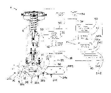
[0023] Turning now to the drawings, FIG. 1 illustrates a system 8 and
apparatus for sensing
and/or monitoring cavitation in liquid flowing through a control valve 10 or
other flow control
device according to the teachings of the present disclosure. The system 8
includes a flow control
device, such as control valve 10 and/or pipes 24a and 24b, one or more
acoustic emission sensors,
such as acoustic emission sensors 26a-d, and a computerized processor, such as
processor 30. The
system 8 may be part of a larger process control plant, _______________
5b
Date Re9ue/Date Received 2020-11-11
such as an oil refinery or chemical processing plant, as is understood in the
art. For example, the
system 8 may be integrated into a computerized control system for a process
control plant, such
as the system described in detail in U.S. Patent No. 6,954,713. The system 8
senses acoustic
signals in fluid flow, such as acoustic signals generated by cavitation in or
near the control valve
10, and identifies a cavitation flow condition based on the acoustic signals.
The acoustic signals
may include transient acoustic energy data caused by the formation of gas
bubbles and/or the
subsequent collapsing of the gas bubbles as part of the cavitation. The
cavitation flow condition
may be identified by the presence of cavitation events, which have preselected
characteristics.
Preferably, the system 8 monitors a cavitation level based on a rate of
cavitation events and/or an
intensity of individual cavitation events. The system 8 can provide a report
of the cavitation flow
condition in the liquid. The report may be provided to an operator and/or to a
controller for the
control valve 10. In some arrangements, the system 8 tracks accumulation of
cavitation over time,
which may be used to predict when maintenance should be scheduled on the
control valve 10. In
some arrangements, the system 8 monitors changes in the cavitation level,
which may be used to
provide an alert for statistically significant changes in the cavitation
level. In some arrangements,
the cavitation level may be correlated with a position of the control valve to
identify potentially
problematic operating conditions. Although the example shown in the drawings
relates
specifically to a control valve 10, the system 8 and apparatus and methods may
be arranged to
monitor cavitation in other types of flow control devices for process liquids,
such as pipes and
reducers, in a similar manner as described with respect to the example control
valve 10.
[0024] The control valve 10 includes a valve body 12, a flow control member
14, and an actuator
16. A fluid flow path 18 extends through the valve body 12. The fluid flow
path 18 extends at
least partly from an inlet 20 into the valve body 12, through a throat 28, to
an outlet 22 out of the
valve body 12. The fluid flow path 18 may also be defined at least partly by a
pipe 24a connected
to the inlet 20 and/or a pipe 24b connected to the outlet 22. Additional
components of the control
valve 10 are well known and are not explained in further detail herein for the
sake of brevity.
[0025] One or more of the acoustic emission sensors 26a, 26b, 26c, and 26d are
disposed along
the fluid flow path 18. Cavitation events that act on or near the inside
surface of the valve body
12 are transmitted through the valve body to one or more of the acoustic
emission sensors 26a-d.
The acoustic emission sensors 26a-d detect acoustic signals and provide __
6
Date Re9ue/Date Received 2020-11-11
CA 02921099 2016-02-10
WO 2015/031416 PCMJS2014/052798
acoustic information representative of the detected acoustic signals. The
acoustic signals
sensed by the acoustic emission sensors may include, for example, vibrations
and noise
caused by the collapsing of bubbles within the fluid during cavitation. The
acoustic signals
also may include energy released in the valve body 12 when a bubble collapses
close enough
to the inner wall of the valve body that a small amount of damage occurs to
the valve body.
Preferably, the acoustic emission sensors 26a-d identify and capture the
acoustic signals as
individual and discrete occurrences of a transient elastic energy wave. As
understood in the
art, an elastic energy wave is an acoustic energy wave that is traveling
through a solid, as
opposed to an acoustic energy wave that is traveling through air or liquid.
The acoustic
information transmitted by the acoustic emission sensors 26a-d is preferably
provided in the
form of signals, such as electronic acoustic emission signals, generated in
response to the
sensed acoustic signals. The acoustic emission sensors 26a-d are preferably
piezoelectric
sensors, such as piezoceramic sensors, and may be high frequency piezoceramic
sensors,
such as the VS900-RIC acoustic emission sensors available from Vallen Systeme
GmbH, of
Icking, Germany, although other high frequency acoustic emission sensors may
be used. In
some arrangements, one or more of the acoustic emission sensors also or
alternatively may
include capacitive acoustic emission sensors, laser interferometer acoustic
emission sensors,
and/or other types of electronic acoustic emission sensors capable of
detecting and receiving
the acoustic signals produced by cavitation within or near the control valve
10.
[0026] The system 8 does not necessarily include each or all of the acoustic
emission
sensors 26a-d in all arrangements; however, preferably at least one of the
acoustic emission
sensors 26a-d is arranged to acquire the acoustic signals caused by
cavitation. In the
exemplary arrangement of FIG. 1, each of the acoustic emission sensors 26a-d
is disposed at
one or more selected locations, which may be selected based on the likelihood
of
experiencing cavitation caused by the control valve 10. The acoustic emission
sensors 26a-d
are arranged to detect acoustic signals emanating from fluid flowing along the
fluid flow path
18 and passing as elastic waves through one or more solid components of the
control valve
10, such as the wall of the valve body 12.
[0027] The acoustic emission sensors 26a-c are disposed on the valve body 12
and the pipe
24b at one or more locations where cavitation is most likely to occur. One
common region
where cavitation can occur is in the area of the fluid flow path 18
immediately downstream of
the flow control member 14 and/or the trim, such as between the throat 28 and
the outlet 22.
Therefore, the acoustic emission sensors 26a and 26b are located at different
selected
7
CA 02921099 2016-02-10
WO 2015/031416 PCMJS2014/052798
locations along the fluid flow path 18 between the throat 28 and the outlet
22. For example,
the acoustic emission sensor 26a is disposed adjacent the throat 28, and the
acoustic emission
sensor 26b is disposed adjacent the outlet 22. During cavitation, the
formation of the gas
bubbles can create a first acoustic signal pattern and the implosion of the
gas bubbles can
create a second acoustic signal pattern. The acoustic emission sensors 26a-c
detect these first
and second acoustic signal patterns and create electrical acoustic emission
signals
representative of these acoustic signal patterns in a manner well understood
in the art. In this
arrangement, the acoustic emission sensor 26a may be more likely to detect the
formation of
bubbles, or "flashing," and the acoustic emission sensor 26b may be more
likely to detect the
implosion of the bubbles. Cavitation may also occur or continue to occur
further downstream
of the outlet 22, such as in a region of the pipe 24b immediately adjacent the
outlet 22.
Therefore, the acoustic emission sensor 26c is disposed on the pipe 24b
adjacent the
connection with the outlet 22. The acoustic emission sensor 26c may also
detect the
implosion of the bubbles or may detect fewer bubble implosions or normal flow,
i.e., flow
without cavitation present.
[0028] The acoustic emission sensor 26d is disposed along the fluid flow path
18 at one or
more locations proximate the control valve 10 that are not likely to
experience cavitation.
The acoustic emission sensor 26d may be located on an upstream side of the
flow control
member 14. For example, the acoustic emission sensor 26d may be coupled on an
exterior
surface the valve body 12 between the inlet 20 and the flow control member 14,
as illustrated
in FIG. 1, or on the pipe 24a. Because the acoustic emission sensor 26d is
located where
cavitation is not likely to occur, the acoustic emission sensor 26d provides
baseline acoustic
information that may be used as a baseline measure of normal flow, i.e., flow
without
cavitation present. The baseline acoustic information generated by the
acoustic emission
sensor 26d may be in the form of electrical acoustic emission signals called
baseline emission
signals. The baseline acoustic information may be compared against the
acoustic information
derived from the acoustic emission signals generated by the acoustic emission
sensors 26a-c
to calibrate the acoustic emission sensors 26a-c, detect the presence of
cavitation in the fluid,
and/or measure the intensity of cavitation.
[0029] Preferably, the acoustic emission sensors 26a-d are secured to the
exterior of the
respective valve body 12 and pipes 24a and 24b, i.e., on the side of the wall
opposite the fluid
flow path 18. In this arrangement, the acoustic emission sensors 26a-d can
detect the
acoustic signals from cavitation along the flow path 18 without breaching the
boundary of the
8
CA 02921099 2016-02-10
WO 2015/031416 PCMJS2014/052798
flow path. That is, the flow path 18 remains sealed without the acoustic
emission sensors
26a-d or lead wires extending through the boundary wall, such as at a seal or
flange. By not
breaching the boundary of the flow path, the system 8 can acquire the acoustic
signals in a
manner that is less likely to cause leaks. The acoustic emission sensors 26a-d
may be
operatively coupled to the valve body 12 and/or the pipes 24a, 24b by any
method sufficient
to maintain the acoustic emission sensors 26a-d disposed on the respective
valve body 12
and/or pipes 24a, 24b and able to adequately sense acoustic signals in the
form of vibrations
emanating from the liquid flowing along the fluid flow path 18. A preferred
acoustic
coupling for acoustic emission monitoring of cavitation is similar to the
process described in
ASTM standard E650 as is understood in the art. For example, it is typically
important to
maintain maximum face-to-face contact between the active detection area on the
face of the
acoustic emission sensor and the surface of the flow control device with a
minimum of gaps
or air space therebetween. Therefore, the acoustic emission sensors 26a-d may
be coupled
directly to the exterior surface of the respective valve body 12 and/or pipes
24a, 24b, for
example with welds, fasteners, clamps, or adhesives. Preferably, the shape of
the face of the
acoustic emission sensor is complementary to the corresponding shape of the
receiving
surface of valve body or pipe. In some cases, a thin layer of grease or gel
may be disposed
between the receiving surface and the face of the sensor and manipulated so as
to eliminate
any air bubbles therebetween.
[0030] A thermal standoff (not shown) may be disposed between the face of the
acoustic
emission sensor and the receiving surface to insulate the acoustic emission
sensor from the
valve body. Use of a thermal standoff can be advantageous where the valve
operates at high
temperature or if access to the valve is limited. The thermal standoff may be
a piece of metal
with one or more exposed outside surfaces arranged to dissipate heat.
Inclusion of a thermal
standoff may also require some compensation and/or corrections to the acoustic
emission
signals to accommodate for variances caused by the thermal standoff.
[0031] The processor 30 is operatively connected to one or more of the
acoustic emission
sensors 26a-d to receive the respective acoustic information generated
thereby. The acoustic
information may be communicated in any suitable manner, such as by receiving
the acoustic
emission signals directly by a wired or wireless communication pathway or by
indirectly
receiving the acoustic information via other possible communication pathways.
Preferably,
the acoustic information is provided in the form of electric acoustic emission
signals
generated by the acoustic emission sensors 26a-d in response to the sensed
acoustic signals.
9
CA 02921099 2016-02-10
WO 2015/031416 PCMJS2014/052798
The processor 30 is configured to identify and monitor the presence of
cavitation in the fluid
flow path 18 based on the acoustic information received from any one or more
of the acoustic
emission sensors 26a, 26b, 26c, and/or 26d. The processor 30 is also
configured to extract
data from the acoustic information and use the acoustic information to
determine additional
information about or relevant to the control valve 10 based on the monitored
cavitation. The
processor 30 may be dedicated to monitoring the presence of cavitation at the
flow control
device, or the processor 30 may be integrated with other computerized systems
that perform
other process control functions. For example, the processor 30 may be
integrated with a
positioner 32 for controlling the position of the flow control member 14. The
positioner 32
may be a typical digital valve positioner, such as a Fisher FieldviewTM
DVC6000 digital
valve controller, available from Emerson Process Management, of Mashalltown,
Iowa. The
processor 30 may be connected to and/or integrated with one or more other
plant control
system computers 34, for example, with a bus 36.
[0032] In one arrangement, the processor 30 includes a digital signal
processor (DSP) 38,
one or more digital or other electronic memory modules 40, one or more
computer processors
42, and other known computer components, such as input/output devices, data
communication devices, application specific integrated circuits (ASICs),
and/or software
modules for accomplishing the functions and methods described herein in a
manner that
would be understood by a person of ordinary skill in the digital signal
processing and
computing arts. The DSP 38 may include an analog-to-digital (AD) converter. In
other
arrangements, the processor 30 may include embedded signal processing routines
to process
the acoustic emission signals received from the acoustic emission sensors 26a-
d instead of a
dedicated DSP 38. The computer processor 30 may include all of the functional
components
above in a single unit or one or more of the components may be remote and
operatively
connected by any known data communication arrangement, such as via the
FoundationTM
Fieldbus protocol, HART protocol, internet, Ethernet, and/or or other suitable
data
communication arrangements as would be understood by a person of ordinary
skill. Data
communication between various components of the system 8 may be via one or
more wired
connections and/or wireless connections.
[0033] The processor 30 includes program instructions or is arranged to access
such
program instructions implemented by means of appropriate hardware and/or
software
sufficient to receive the acoustic information generated by the acoustic
emission sensors 26a-
d and to process the received acoustic information in a method sufficient to
monitor
cavitation levels in the fluid flow path based on the rate and intensity of
individual cavitation
events. To accomplish this, one or more routines, preferably in the form of
sets of programming
instructions, are accessible to the processor 30. In one arrangement, an
acquisition routine 50, a
filtering routine 52, and one or more monitoring routines 54a, 54b, 54c, and
54d are stored in the
memory 40. In other arrangements, the programming instructions may also or
alternatively be
embedded directly within the computer processor 42 and/or may be stored
elsewhere and
accessed remotely by the computer processor 42. The acquisition routine 50
causes the processor
30 to receive the acoustic information generated by the acoustic emission
sensors 26a-d, such as
by receiving the acoustic emission signals ("AE signals"). The filtering
routine 52 filters the
received AE signals to select only signals that meet one or more predefined
characteristics
indicative of cavitation at the control valve 10 and ignoring other signals.
In some arrangements,
filtering may also or alternatively be perfolined by filtering of the acoustic
signals by the acoustic
emission sensors 26a-d and/or by filtering hardware 55. The filter hardware 55
is operatively
located between the acoustic emission sensors 26a-d and the processor 30 so as
to filter the
acoustic emission signals prior to being received at the processor 30. The
monitoring routines
54a-d use the selected signals to identify and monitor cavitation in the
control valve 10 according
to various criteria. Together, the acquisition routine 50, filtering routine
52, and one or more of
the monitoring routines 54a-d may be configured to implement one or more of
the methods
described in detail hereinafter. The routines 50, 52, and 54a-d may be
instructions in the folio of
software, for example stored in the memory 40, and/or hardware, such as
dedicated circuits within
the computer processor 42, the DSP 38, the positioner 32, and/or the sensors
26a-d.
[0034] With reference to FIGS. 2 and 3, a method 100 of monitoring cavitation
in a flow control
device, such as the control valve 10 and/or the pipes 24a or 24b, is
illustrated. The method is
implemented by the system 8 of FIG. 1. The system 8 is configured to acquire
acoustic signals
from fluid flowing through the flow control device with any one or more of the
acoustic emission
sensors 26a-d within a range of frequencies preselected for being likely to be
indicative of
cavitation. The acquired acoustic signals preferably include transient
acoustic energy data
generated by cavitation. The system 8 may be configured to provide a level of
filtering at the
acoustic emission sensors, for example, by adjusting sensitivity parameters of
the acoustic
emission sensors, selecting acoustic emissions sensors with predefined
sensitivity ranges, and/or
adjusting output parameters for the acoustic emission signal output by the
acoustic emission
sensors. In some arrangements, the acoustic emission ___________________
11
Date Re9ue/Date Received 2020-11-11
CA 02921099 2016-02-10
WO 2015/031416 PCT/1JS2014/052798
sensors 26a-d are configured to filter the acoustic signals so as to provide a
first level of
filtering by only acquiring acoustic signals within the range. For example,
the range in some
arrangements is between approximately 500 kHz and approximately 1600 kHz, but
other
ranges may be used. The system 8 may be configured to provide a level of
filtering between
the acoustic emission sensors and the processor 30, for example, with
filtering hardware 55
operatively located between the acoustic emission sensors and the processor
30. The system
may be configured to provide a level of filtering, for example, by adjusting
receiving limit
parameters at the processor 30, such as with instruction routines or programs
implemented
from software or hardware. The receiving limit parameters may include one or
more
parameters within the AD converter, DSP 38, or other hardware or software
components of
the processor 30. The processor 30 receives acoustic information in the form
of AE signals
from one or more of the acoustic information sensors 26a-d about acoustic
signals caused by
transient events that occur with each bubble formation, cavity, or bubble
collapse during a
cavitation event within the flow control device and uses the data to calculate
a cavitation
level.
[0035] Block 102 acquires acoustic signals from the flow control device at
least within the
preselected range of frequencies. In one arrangement, the acoustic signals are
acquired
initially by one or more of the acoustic emission sensors 26a-d. The acoustic
emission
sensors 26a-d are configured to acquire transient acoustic energy data within
a range of
frequencies, such as at least between approximately 500 kHz and approximately
1600 kHz.
Acoustic signals acquired by either of the sensors 26a and 26b, for example,
may be used to
provide direct acoustic information regarding cavitation occurrences within
the flow control
valve 10 downstream of the throat 28. Acoustic signals acquired by the sensor
26c may
provide direct information regarding cavitation occurrences within the pipe
24b adjacent the
downstream outlet 22 of the control valve 10. Acoustic signals acquired by the
sensor 26d
may provide control or baseline information relative to standard liquid flow
without
cavitation. For purposes of the following descriptions, the acoustic signals
are obtained by
the acoustic emission sensor 26a; however, the same process may be followed
for any one of
the acoustic emission sensors 26a-d. The acoustic emission sensor 26a then
generates
acoustic information in the form of an AE signal representative of the
acquired transient
acoustic energy data. The AE signal is communicated to the processor 30, for
example, via
wires 56 and/or other suitable electronic data communication pathway. The
block 102 may
be executed, for example, by the acquisition routine 50 of the processor 30.
12
CA 02921099 2016-02-10
WO 2015/031416 PCMJS2014/052798
[0036] Block 104 determines if the AE signal from block 102 is caused by a
cavitation
event according to predefined parameters. A cavitation event is defined by one
or more
predefined characteristics of the AE signal. In one arrangement, a cavitation
event is defined
as an acquired AE signal that is above a predefined minimum threshold and
within a
predefined filter range. The filter range can include the minimum threshold
(i.e., a low end)
and a predefined maximum cutoff (i.e., a high end). For example, an entire AE
signal
waveform may be considered based on amplitude and frequency of the signal. The
amplitude
of the AE signal waveform is representative of the acoustic energy decibels
(dB) of a
given waveform. Preferably, the dB AE is measured in microvolts and reported
in dB, E by
calculating -20 Log10 (Peak Amplitude Voltage/1 microvolt). It may be
determined whether
the waveform of the AE signal meets one or more threshold parameters, such as
an amplitude
within a specified range and/or the hit rate of high amplitude waveforms.
However, other
threshold and filter parameters may be used. If the AE signal exceeds the
predetermined
minimum threshold and is within the predefined filter range, then the AE
signal is considered
to be a "hit" caused by a cavitation event that, for example, may affect the
maintenance of the
flow control device. In this case, the AE signal is selected as being caused
by a cavitation
event and control transfers to block 106. If the AE signal does not exceed the
predetermined
minimum threshold and is not within the predefined filter range, then the AE
signal is ignored
and control returns to block 102 to acquire another AE signal from the
acoustic emission
sensor 26a. The block 104 may be executed, for example, by the filtering
routine 52 of the
processor 30.
[0037] Block 106 records preselected characteristics of the selected AE signal
from block
104 representative of various acoustic information from the cavitation event
captured by the
acoustic emission sensor 26a. With reference to FIG. 2A, individual cavitation
events
typically occur in groups during a period of cavitation flow. FIG. 2A
illustrates an example
waveform WF for a transient event that may be similar to a group of cavitation
events during
a period of cavitation flow. The upper graph shows the voltage of acquired
signals S and the
lower graph shows threshold crossings of the signals. The sensor output
voltage, as
illustrated in the upper graph, is typically reported in acoustic energy
decibels (i.e., dB).
The signals S start at time to with no cavitation events, cross a
predetermined threshold level
T at time ti, rise to a peak amplitude at time t2, fall back below the
threshold level T at time
t3, and fall to no cavitation events at time t4. Other characteristics may
include additional
individual features of the acquired signal S, such as the number, rate, and/or
time duration of
13
CA 02921099 2016-02-10
WO 2015/031416 PCMJS2014/052798
threshold crossings TC within the group, rise time from a first threshold
crossing to a largest
amplitude acquired signal S within the group of hits, and accumulated energy
of a group of
hits, each of which are well understood in the art of acoustic waveform
processing. The
threshold crossings TC may correspond to the hits and counts discussed in
detail hereinafter
relative to FIG. 4.
[0038] Returning to FIG. 2, block 108 determines a cavitation level value from
the
characteristics recorded at block 106. The cavitation level is determined
based on the rate of
cavitation events and the intensity of the cavitation events. In one exemplary
method,
illustrated in FIG. 3, block 108 includes a first calculation related to the
rate of cavitation
events at block 110, a second calculation related to the intensity of each
cavitation event at
block 112, and a third calculation related to the cavitation level value at
block 114.
[0039] Block 110 calculates a hit rate by recording the number of cavitation
events that
occur during a selected period of time. For example, the hit rate H may be the
number of
cavitation events N that occur during a period of time t immediately preceding
the present
time T divided by the period of time. This may be represented as the equation:
H = NT_t/(T-t).
In most situations, the hit rate is calculated as the number of cavitation
events that occur over
a period of time of at most up to a few seconds, such as between about 1
second and about 10
seconds. However, longer or shorter periods of time may be used in some
situations. The hit
rate is reported as the number of cavitation events per second during that
period of time.
With reference to FIG. 2A, in one example, a hit rate R may be calculated as
the number of
individual threshold crossings TC that occur during of a given period of
cavitation flow (e.g.,
from ti to t3) divided by the duration of the period of cavitation flow (e.g.,
t341).
[0040] Block 112 calculates an intensity of each individual cavitation event
based on the
characteristics recorded at block 106. The intensity is based on a measure of
energy released
by the cavitation event. For example, the intensity may be correlated with the
amplitude,
duration, area under the wave, and/or other individual features of the
acquired signal S. In
one arrangement, the intensity is determined as the absolute value of the area
under one
waveform or a group of waveforms, as illustrated in FIG. 2A. Energy may be
calculated as
the integration of the sensor output voltage squared over time, i.e., Energy =
Integral (v2)(dt),
where v is the sensor output voltage and dt is the change in time, as is
understood in the art.
Blocks 110 and 112 may be performed in any order or simultaneously.
14
CA 02921099 2016-02-10
WO 2015/031416 PCMJS2014/052798
[0041] Block 114 calculates a value of the cavitation level based on the hit
rate calculated
at block 110 and the intensity calculated at block 112. The value of the
cavitation level is
preferably calculated as a function of both the hit rate and the intensity.
That is, C =
where C is the cavitation level, R is the hit rate, I is the intensity.
Preferably, the cavitation
level is directly proportional to the hit rate and the intensity. Different
specific equation
relationships can be used to calculate the cavitation level C depending on the
specific data
received and the specific form of the output desired.
[0042] The blocks 106-114 may be executed, for example, by the monitoring
routine 54a
of the processor 30.
[0043] The cavitation level determined by the method 100 may have several
different uses,
such as determining if cavitation is occurring, determining an intensity of
cavitation activity
at some point in time, and/or tracking an accumulation of cavitation and/or
damage over a
period of time. This information may be useful, for example, in monitoring
performance of
the flow control device, identifying non-ideal functioning of the flow control
device, and/or
predicting maintenance needs without disassembling or having total failure of
the flow
control device. The following methods build on the method 100 to utilize the
information
regarding cavitation levels provided by the method of monitoring.
[0044] FIG. 4 illustrates another method 200 of monitoring cavitation of that
may be
useful, for example, for estimating damage to a flow control device, such as
the control valve
10. The method 200 may be implemented with the system 8 illustrated in FIG. 1.
The
method 200 includes steps of the method 100 for monitoring cavitation levels
and uses the
information about the cavitation levels to monitor the cavitation over a
period of time, and to
monitor an accumulation of cavitation activity over time. The information may
be used to
estimate the amount of damage sustained by the flow control device, to track
the damage,
and/or to predict and/or plan for maintenance to repair the damage.
[0045] The system of FIG. 1 is configured to acquire transient acoustic energy
data from
any one or more of the acoustic emission sensors 26a-d within a selected
frequency range, as
described in detail previously in relation to the method 100.
[0046] At block 102, the system of FIG. 1 acquires transient acoustic energy
data from any
one or more of the acoustic emission sensors 26a-d at least within a
preselected range of
frequencies and generates AE signals, as described in detail previously.
CA 02921099 2016-02-10
WO 2015/031416 PCT/1JS2014/052798
[0047] At block 104, the processor 30 determines whether the AE signal is
caused by a
cavitation event according to predefined parameters and selects a signal for
further processing
if it is within the predefined parameters, as described in detail previously.
[0048] At block 106, the processor 30 records selected characteristics of the
selected
signal, such as the waveform or other individual features of the acoustic
emission signal, as
described in detail previously.
[0049] At block 110, the processor 30 determines the rate of cavitation
events, for
example, by calculating the hit rate as described previously.
[0050] At block 112, the processor 30 determines the intensity of each
cavitation event. for
example by calculating the amount of energy per cavitation event as described
previously.
[0051] At block 114a, the processor 30 calculates a cavitation level and
determines
whether the cavitation level exceeds a predetermined cavitation level
threshold. If the
cavitation level exceeds the predetermined cavitation level threshold, then
control passes to
block 116. If the cavitation level does not exceed the predetermined
cavitation level
threshold, then control returns to the block 102 to acquire another AE signal.
In one
exemplary arrangement, the determination of whether the cavitation level
exceeds the
predetermined cavitation level threshold may include an independent comparison
of each or
either of the hit rate and the intensity with separate threshold values for
the cavitation event.
The hit rate calculated at block 110 is compared with a predetermined hit rate
threshold
value. The intensity is compared with a predetermined intensity threshold
value. In some
arrangements, the cavitation level is determined to exceed the predetermined
cavitation level
threshold if both the hit rate and the intensity exceed the respective hit
rate threshold value
and the intensity threshold value. In other arrangements, the cavitation level
is determined to
exceed the predetermined cavitation level threshold if either the hit rate or
the intensity
exceed the respective hit rate threshold value and the intensity threshold
value. In another
exemplary arrangement, the cavitation level is calculated as described
previously for the
block 114 of FIG. 3 as a composite value depending on each of the hit rate and
the intensity.
The composite value of the cavitation level is compared with a predetermined
composite
cavitation level threshold value. If the composite value exceeds the composite
cavitation
level threshold, then the cavitation level is determined to exceed the
predetermined cavitation
level threshold. A further exemplary arrangement may include a combination of
the previous
two exemplary arrangements. Under any of these schemes, the cavitation level
calculated is a
16
CA 02921099 2016-02-10
WO 2015/031416 PCMJS2014/052798
function of both the rate of cavitation events and the intensity of the
individual cavitation
events, and is preferably a directly proportional function, as explained
previously. If the
cavitation level does not exceed the predetermined cavitation level threshold,
then control
returns to block 102 to acquire another AE signal from one or more of the
acoustic energy
sensors 26a-d. If the cavitation level exceeds the predetermined cavitation
level threshold,
then the processor 30 institutes further monitoring protocols that may, for
example, be used to
estimate damage to the flow control device, which may be performed in one or
more steps of
blocks 116, 118, and 120, described hereinafter.
[0052] Block 116 generates an alert indicating that the cavitation level
exceeds the
predetermined threshold value or values. The alert is preferably generated by
the processor
30.
[0053] Block 118 tracks the number of times and/or the amount of time that the
cavitation
level exceeds a predetermined threshold so that an estimate of accumulated
damage to the
flow control device caused by cavitation may be monitored. In some
arrangements, the block
118 increments a counter for the number of times the cavitation level has been
determined to
exceed the predetermined cavitation level. The block 118 may increment the
counter each
time an alert is generated at block 116, or the block 118 may increment the
counter in direct
response to the positive determination at block 114a without generating the
alert at block 116.
The counter is preferably a digital electronic counter within the processor
30, such as stored
within an electronic memory, database, and/or other digital counter mechanism;
however,
other types of counters, such as an analog counter, may be used. In some
arrangements, the
block 118 tracks the accumulated amount of time that the cavitation level
exceeds the
predetermined threshold. The block 118 may identify the time duration of each
incidence
during which the cavitation level exceeds the predetermined threshold and
additively
accumulate each such time duration. The additive accumulation would represent
the
accumulated amount of time that the cavitation level exceeds the predetermined
threshold.
[0054] Block 120 provides a notification to a user of the existence of an
alert condition.
The notification may be generated by the processor 30, for example, in the
form of an
electronic notification sent to a display screen.
[0055] Block 122 returns control to the block 102.
[0056] The count accumulated by the counter at block 118 may be used to
estimate and/or
track damage to the flow control device. Specifically, the count can be a
proxy for the
17
CA 02921099 2016-02-10
WO 2015/031416 PCMJS2014/052798
amount of damage sustained by the flow control device over time. The count may
be
correlated to estimations of damage of the flow control device by correlations
between the
number of cavitation events accumulated and the amount of damage sustained by
the flow
control device. For example, as the count (i.e., the number cavitation events
above the
predetermined cavitation level threshold) increases, the estimated accumulated
damage to the
flow control device is assumed to also increase. The correlation may be
linear, non-linear,
exponential, or another suitable relation that, for example, can be determined
experimentally
and/or theoretically. Thus, a large number of counts may indicate an estimate
of a large
amount of damage to the flow control device caused by cavitation. Conversely,
a low
number of counts may indicate an estimate of a low amount of damage to the
flow control
device caused by cavitation.
[0057] The count accumulated by the counter may be used to identify when the
flow
control device needs to be serviced to repair damage caused by or indicated by
cavitation.
For example, the count may be set to zero when the flow control device is new
and
undamaged. When the count reaches a predefined limit value, the flow control
device may
be designated for service. In some arrangements, a report may be created
indicating that the
control valve 10 is due for service when the count reaches some predetermined
limit value.
In this arrangement, the estimation of damage is based on an accumulation of
damage that is
dependent on one or both of the rate and intensity of cavitation events in the
flow control
device. Further. the estimation of damage may be adjusted to weight the
estimate more or
less on either of the rate or the intensity of the cavitation events. The
predetermined limit
value may be determined experimentally and/or theoretically.
[0058] The count in some arrangements may be used to predict a time in the
future when
the flow control device should be serviced to repair damage caused by or
indicated by
cavitation. For example, a velocity of the alerts. i.e., a rate of the number
of alerts per some
increment of time, may be used in conjunction with the accumulated sum of
alerts over a
period of time to predict a time in the future that the predetermined limit
value will be
reached.
[0059] Blocks 116, 118, 120, and 122 may be implemented sequentially or
simultaneously.
Further additional functional steps or fewer functional steps may be
implemented in
estimating and/or tracking damage caused to the flow control device by
cavitation. Blocks
114a-122 may be executed, for example, by the monitoring routine 54b of the
processor 30.
18
CA 02921099 2016-02-10
WO 2015/031416 PCT/1JS2014/052798
[0060] FIG. 5 illustrates a method 300 of monitoring cavitation that may be
used to
monitor a damage rate to a flow control device, such as the control valve 10.
The method
300 may be implemented with the apparatus illustrated in FIG. 1. The method
300 includes
steps of the methods 100 and 200 for monitoring cavitation levels and uses the
information
about the cavitation levels to determine information that may be used to
estimate the rate of
damage sustained by the flow control device.
[0061] The system of FIG. 1 is configured to acquire transient acoustic energy
data from
any one or more of the acoustic emission sensors 26a-d between approximately
500 kHz and
approximately 1600 kHz, preferably in the same manner as described previously
relative to
methods 100 and 200. In addition, blocks 102, 104, 106, 108 and 112 are
implemented by the
processor 30 in the same manner as previously described relative to methods
100 and 200, the
description of which is not repeated here for brevity.
[0062] Block 124 calculates one or more trends of the cavitation events. In
one
arrangement, block 124 determines a trend of the hit rate and a trend of the
intensity values.
The trends may be determined graphically and/or statistically. For example, if
the hit rate is
increasing over a sample time period, a hit rate trend may be positive, if the
hit rate is
decreasing over the sample time period, the hit rate trend may be negative,
and if the hit rate
is remaining unchanged over the sample time period, the hit rate trend may be
steady (i.e.,
zero). Similarly, if the intensity values are increasing, decreasing, or
remaining unchanged
over a sample time period, an intensity trend may be positive, negative, or
steady,
respectively. The sample time period may be selected to be any suitable time
period. For
example, the sample time period may be a period of seconds, minutes, hours,
days, weeks, or
longer or shorter, depending on the sensitivity desired. The sample time
periods for each of
the hit rate trend and the intensity trend may be the same or different from
each other. In
another arrangement, block 124 determines a trend that combines and
incorporates each of
the hit rate data and intensity data into a composite cavitation activity
trend. The composite
cavitation activity trend may be calculated with different weightings and/or
additional
information as desired.
[0063] Block 126 determines whether one or more of the trends calculated at
block 124
shows whether cavitation activity within the flow control device is increasing
in a statistically
significant manner. Statistical significance may be determined in many ways.
For example,
statistical significance may be based on a rolling average and/or on a
selected standard
19
deviation multiple of a selected variable. For example, the block 126 may
deteimine whether a
rolling average of the trends calculated at block 124 exceeds a preselected
value and/or if the
cavitation activity is increasing at a rate that exceeds a preselected rate
within a preselected level
of statistical significance relative to a standard deviation. If so, then
control passes to block 128.
Otherwise, control returns to the block 102.
[0064] Block 128 generates an alert that indicates that the cavitation level
is increasing. At block
130, the processor 30 notifies a user that the cavitation level is increasing.
Blocks 128 and 130
may be executed in any desired order. The alert generated at block 128 may be
used, for example,
to monitor the flow control device for increases in normal levels of
cavitation that may be
indicative of some problem, such as a malfunction or maintenance need, that
would not otherwise
be readily visible to an operator from a visual inspection or other
infoimation.
[0065] At block 122, control returns to block 102 to continue monitoring for
transient acoustic
energy data from the flow control device.
[0066] The blocks 122-130 may be executed, for example, by the monitoring
routine 54c of the
processor 30.
[0067] In some arrangements, two or more of the methods 100, 200, and 300 may
be
implemented together or simultaneously to provide a several types of
information to a user. For
example, blocks 102 through 112 may be executed sequentially, and then two or
more of each of
block 114, blocks 114a through 120, and blocks 124 through 130 may be executed
to provide
each of a cavitation level, an estimate of accumulated damage, and a damage
rate.
[0068] In some arrangements, one or more of the acoustic emission sensors 26a-
d are integrated
with the positioner 32. In some arrangements, one or more of the acoustic
emission sensors 26a-d
are integrated with asset management software of the computerized control
system of a process
control plant. In some arrangements, one or more of the acoustic emission
sensors 26a-d are
integrated with a process control system in a process control plant. For
example, any one or more
of the acoustic emission sensors 26a-d could be tied directly to its own
dedicated processor 30, or
may be implemented as a component of the positioner 32, the DSP 38, or higher
level process
software, including asset management software, such as the AMS Suite available
from Emerson
Process Management, or top level process control system, such as the DeltaV
digital
automation system from Emerson Process Management. _____________________
Date Re9ue/Date Received 2020-11-11
CA 02921099 2016-02-10
WO 2015/031416 PCT/1JS2014/052798
[0069] In some arrangements, the processor 30 is configured to identify a
problematic flow
condition based on the position of the control member 14. The processor 30 is
configured to
receive position information about the position of the flow control member 14
from the
positioner 32. The position information is used to identify potentially
problematic operating
conditions based on the cavitation level determined by any one of methods 100,
200, or 300.
The position information may be correlated with expected cavitation levels for
different
positions, and the expected cavitation level is compared with an actual
cavitation level, such
as calculated at bock 114. For example, it may be found experimentally that
the amount of
cavitation in a given control valve varies according to some identifiable
function of the
position of the flow control member 14 under some given flow conditions. A
significant
deviation in the actual cavitation level from the expected cavitation level
may indicate that
the flow control member 14 is not in the position it is supposed to be in,
that a component is
broken or significantly worn, or that the flow conditions are different than
the given flow
conditions. Thus, a significant deviation between the expected cavitation
level and the actual
cavitation level may serve as a proxy to identify potential problems with the
control valve
and/or the flow conditions through the control valve 10, which may require
further
investigation.
[0070] In one exemplary arrangement, the routine 54d is implemented by the
processor 30
to execute a method 400, illustrated in FIG. 6. Block 402 retrieves position
information from
the positioner 32, for example via wires 60 or other suitable communication
pathway. Block
404 retrieves an expected cavitation level correlated to that position. The
expected cavitation
level may be retrieved, for example, from a database in the memory 40. Block
406 retrieves
the actual cavitation level, for example, from the block 114 or 114a. Block
408 compares the
actual cavitation level with the expected cavitation level. If the actual
cavitation deviates
significantly from the expected cavitation, then an alert is generated at
block 410. The alert
may be provided to an operator or other components of the process control
system to indicate
that further diagnostics of the control valve 10 may be needed. Whether a
deviation is
considered significant is determined by a preselected level of significance,
which may be
selected according any desired set of parameters. The method 400 may return
back to block
402 after either of blocks 408 or 410 as indicated. In some arrangements, the
alert is
provided to an operator to alert the operator to change the operating position
of the valve.
[0071] In some arrangements, the processor 30 is configured to differentiate
between a
normal flow condition and a cavitation flow condition above a predefined
threshold
21
CA 02921099 2016-02-10
WO 2015/031416 PCMJS2014/052798
cavitation level, and generate a report relative to the differential. At least
two ways of
calculating the differential may include: 1) calculating a differential
between two locations at
the same time, called a "position differential," and 2) calculating a
differential between two
times (e.g., at tO and T) at the same location, called a "temporal
differential." To determine a
position differential, for example, a baseline "normal" flow condition may be
identified by
using baseline acoustic signals from the acoustic emission sensor 26d to
define a normal flow
condition that does not have an elevated cavitation level. To determine a
temporal
differential, for example, a baseline "normal" flow condition may be
identified when the flow
control device is new and operating under conditions known or assumed to not
have an
elevated cavitation level. The processor 30 may include a routine 54e to
compare the
acoustic information associated with normal flow conditions with corresponding
acoustic
information from the acoustic information sensors 26a-c to determine a
difference between
the baseline or normal flow condition and the flow conditions in the areas
likely to
experience cavitation. The differences may be generated into one or more
reports, which
may be used for further analysis and guidance relative to operation and/or
maintenance of the
flow control device.
INDUSTRIAL APPLICABILITY
[0072] A system, apparatus, and/or method according the teachings of the
present
disclosure is useful for monitoring cavitation in liquid flowing through a
process control
device, such as a control valve or pipe, as described in the technical example
provided herein.
However, the system, apparatus, and/or method may have other uses and/or
benefits, and the
disclosure is not limited to the examples elucidated herein. The ability to
sense the presence
of cavitation within or proximate a control valve or other flow control
device, in some
arrangements, can be useful to allow adjustment of the process conditions
through the control
valve. It may also, in some arrangements, be useful for planning maintenance
to repair
damage to the control valve and/or adjacent piping components caused by
cavitation.
[0073] The technical examples described and shown in detail herein are only
exemplary of
one or more aspects of the teachings of the present disclosure for the purpose
of teaching a
person of ordinary skill to make and use the invention or inventions recited
in the appended
claims. Additional aspects, arrangements, and forms within the scope of the
appended claims
are contemplated, the rights to which are expressly reserved.
22