Note: Descriptions are shown in the official language in which they were submitted.
279351-9
1
CYLINDER HEAD
The invention concerns a cylinder head.
As from a given bore (about 150 mm) internal (gas) combustion
engines are fitted with a pre-chamber for ignition boosting. An ignition
source which projects into the pre-chamber ignites the mixture which is
present there and which is relatively rich in the case of a flushed pre-
chamber, whereby ignition flares pass from the pre-chamber into a main
combustion chamber and ignite the mixture present there.
There are various design concepts for supplying fuel to pre-
chambers. In the case of non-flushed pre-chambers mixture is urged out of
the main combustion chamber into the pre-chamber in the compression
stroke.
In the case of flushed pre-chambers there is also the possibility of
additionally supplying the pre-chamber with fuel. That separate fuel supply
is effected by way of a pre-chamber gas valve. That valve can be arranged
in the cylinder head directly or in a spark plug sleeve.
A cylinder head of the general kind set forth is known from the state
of the art. Thus DE 10 2004 016 260 (CATERPILLAR MOTOREN GMBH)
discloses a gas engine with pre-chamber into which gas flows by way of a
passage (3). The illustrated gas engine cylinder head (1) has a flushed pre-
chamber (2) and a separate gas feed passage (3) for supplying a
combustion chamber (4) with gas for the ignition energy, wherein the usual
ignition process is performed by way of a spark plug (8). A solenoid valve
(5) is arranged in the gas feed passage (3) in a receiving region (6) and the
outlet opens directly into the combustion chamber (4).
EP 0480545 (YANMAR DIESEL ENGINE CO) discloses a pre-chamber
gas valve supplied with fuel gas by way of a passage (18). The gas passes
by way of mutually opposite bores into a hollow space (138) from which the
gas passes over into the pre-chamber when the valve is opened. A
disadvantage with the arrangement shown there is the increased amount of
CA 2921627 2017-08-03
279351-9
2
space required as well as the complication and expenditure involved in
component alignment (positionally correct angular orientation for ensuring the
through-flow of gas).
JP H04171256 A shows a valve with a body, a valve spring, a valve
needle, and a lower cavity which is supplied with gas. There is also an upper
cavity in which the valve spring is arranged. The gas is supplied to the valve
from the side. A bore directed radially leads to a very narrow annular
passage. Bores directed radially lead from there to the valve needle.
In US 2,667,155 A a pre-chamber gas valve is disclosed which
comprises a two-piece valve body, a valve spring and a valve needle. The
lower cavity is supplied with gas and the valve spring is located in the upper
cavity. Here again the gas reaches the valve housing via radial bores and
through a narrow annular passage.
The object of the present invention is to provide a cylinder head
which is improved over the state of the art.
A cylinder head according to the invention comprises a cavity for
receiving a pre-chamber gas valve, wherein a recess extending substantially
or completely around the pre-chamber gas valve forms an annular passage
with a wall of the cavity, that surrounds the pre-chamber gas valve,
wherein the annular passage is connected to at least one gas feed passage
for supplying the pre-chamber gas valve with combustion gas, wherein the
annular passage is connected by at least one inclined gas passage with the
lower cavity of the pre-chamber gas valve.
Advantages of the invention are in particular:
- flow of combustion gas into the pre-chamber gas valve by way of the
annular passage in a favorable fashion in regard to flow characteristics,
- solid construction of the valve body by compact arrangement without
additional gas passages,
- symmetry in the lower cavity of the valve possible even with a lateral
intake flow by way of the gas feed passage (with more than one passage),
and
CA 2921627 2017-08-03
CA 02921627 2016-02-23
3
- no defined angular position with respect to the longitudinal axis of
the pre-chamber gas valve is required upon installation,
It can preferably be provided that the angle of the gas passage with
respect to the symmetry of the valve body is of between 20 and 70 . By
such a position of this gas passage, due to a solid construction, particularly
a high stability of the pre-chamber gas valve can be achieved. Moreover,
fluidic conditions of the supplied gas can be optimized by the fact that there
are no acute angles. For the production of such a gas passage it can be
provided that one side of the annular passage is inclined (towards the valve
body). For example, the inclined side of the annular passage can be
perpendicular to the axis of the gas passage. Thereby, the drilling of the
bores is facilitated in production. In a particularly preferred embodiment it
can be provided that the angle of the gas passage with respect to the
symmetry axis of the valve body is of between 20 and 30 .
It can preferably be provided that the annular passage is connected
to a lower cavity of the pre-chamber gas valve by two to six gas passages.
Thereby, an optimal filling of the lower cavity of the pre-chamber gas valve
can be realized - with respect to both fluidic as well as temporal qualities.
Moreover, an essentially symmetrical flow is thereby achieved inside the
valve body.
It can preferably be provided that a spark plug sleeve is fitted into
the cylinder head so that the wall of the cavity, that with the pre-chamber
gas valve forms an annular passage, is formed by the wall of the spark plug
sleeve. That describes the situation where the pre-chamber gas valve is not
fitted directly into the cylinder head but is arranged in a spark plug sleeve.
It can also be provided that the wall of the cavity, that with the pre-
chamber gas valve forms an annular passage, is formed by a wall of the
cylinder head itself. In that case the pre-chamber gas valve is fitted into
the cylinder head directly, that is to say without being by means of a spark
plug sleeve.
It can be provided that in the pre-chamber gas valve is at least one
gas passage communicating the annular passage with a lower cavity of the
pre-chamber gas valve. Therefore at least one gas passage is provided in
CA 02921627 2016-02-23
4
the valve body of the pre-chamber gas valve. In operation of the pre-
chamber gas valve combustion gas is passed through that gas passage from
the annular passage in the direction of the valve seat of the pre-chamber
gas valve. The valve body of the pre-chamber gas valve therefore performs
the task, in the form of the gas passage, of guiding the combustion gas
from the annular passage to the location of discharge at the valve seat.
That structure has proven to be particularly advantageous.
It can be provided that between the seat of the valve head of the
pre-chamber gas valve and the mouth opening of the pre-chamber gas
valve into the pre-chamber or between the seat of the valve head of the
pre-chamber gas valve and the mouth opening of the pre-chamber gas
valve into the passage there is a space. That describes the situation where
the valve head of the pre-chamber gas valve does not directly adjoin the
pre-chamber or the passage leading to the pre-chamber, but a hollow space
is formed therebetween. The provision of that space provides for a
particularly favorable flow of the gas from the pre-chamber gas valve into
the pre-chamber (when the pre-chamber gas valve is arranged flush with
the pre-chamber) or into the passage (with a spaced arrangement of the
pre-chamber gas valve).
It can preferably be provided that the space is of a substantially pear-
shaped configuration which narrows towards the pre-chamber. In that way
the flow of gas from the pre-chamber gas valve into the pre-chamber or
into the passage can be advantageously influenced and nonetheless the
volume can be kept small.
It can be provided that at its outside contour the pre-chamber gas
valve has at least one projection whose flank that is towards the annular
passage also delimits the annular passage and against the other flank of
which bears a sealing means for sealing off the pre-chamber gas valve with
respect to the bore. That provides for component integration in a
particularly simple fashion. The radial passage can be of a radial depth
corresponding to the height of the projection, deeper or however also less
deep. If the height of the projection is considered that allows a less
disturbed geometry in respect of the main valve body. For example an 0-
279351-9
ring can be used as a sealing means, which seals off the pre-chamber gas
valve radially with respect to the bore. Naturally it is also possible to
provide
further projections which can receive further sealant.
It can be provided that a spark plug is arranged in the cylinder head,
5 wherein the spark plug and the pre-chamber gas valve are arranged in a
common cavity of the cylinder head. That is particularly advantageous in
regard to a compact structure. Preferably in that case the spark plug and the
pre-chamber gas valve are arranged in bores which mutually pass through
each other. In that way the spark plug and the pre-chamber gas valve can
involve a still more space-saving installation.
The invention is illustrated in greater detail by the Figures in which:
Figures la through 1 c show a cylinder head with spark plug sleeve,
Figures 2a through 2c show a spark plug sleeve for a cylinder head,
Figures 3a through 3c show a further spark plug sleeve for a cylinder
head,
Figures 4a through 4e show details relating to the gas feed concept,
and
Figures 5a and 5b show a pre-chamber gas valve and a variant
thereof.
Figure la shows a cylinder head 2 with a spark plug sleeve 4 fitted
into the cylinder head 2. In this embodiment a cavity 7 is formed by the spark
plug sleeve 4.
Figures lb and lc show two views of the spark plug sleeve 4.
Figure la shows a longitudinal section through the cavity 7 which
accommodates a spark plug (not shown) and a pre-chamber gas valve 5.
The cavity 7 includes on the one hand a shaft which is concentric
around the axis of symmetry Si, consisting of cylinder portions, for receiving
a spark plug.
The cavity 7 further has a bore 10 with an axis of symmetry S2 for
receiving a pre-chamber gas valve 5.
A passage 8 leads from the pre-chamber gas valve 5 to the pre-
chamber 3. The pre-chamber 3 comprises on the one hand the actual
cavity, that is to say the hollow space in which the ignition of mixture takes
CA 2921627 2017-08-03
279351-9
6
place. The pre-chamber 3 is of course also a physical component. In the
present embodiment the pre-chamber 3 is in the form of a component
separate from the spark plug sleeve 4 and is connected to the spark plug
sleeve 4, for example by pressing.
The spark plug which is not shown for the sake of clarity is introduced
into the spark plug sleeve 4 by way of the shaft concentric with the axis of
symmetry Si, in such a way that it terminates flush with the pre-chamber 3
and its electrodes project into the pre-chamber 3. The pre-chamber 3 is
enriched with combustion gas by the pre-chamber gas valve 5 by way of the
passage 8. After ignition in the pre-chamber 3 ignited mixture passes by way
of the flow transfer bores 9 into the main combustion chamber (not shown).
Figure lb shows a plan view of Figure la. It is possible to see the
parallel cylindrical shafts disposed within the cavity 7 for receiving a spark
plug and a pre-chamber gas valve 5. The spark plug is not shown, as
explained with reference to Figure la. It is possible to see in the pre-
chamber
gas valve 5 an octagon with which the pre-chamber gas valve 5 is screwed
into the spark plug sleeve 4. In the present embodiment there is a largest
bore diameter D1 of the cavity 7, which in a plan view circumscribes the
bores for receiving the spark plug and the pre-chamber gas valve 5. In other
words, in this embodiment, there is a common shaft for spark plug and pre-
chamber gas valve 5.
The center line of that largest bore of the diameter D1 is between the
axes of symmetry Si and S2. The common shaft has advantages in terms
of mounting of the spark plug and the pre-chamber gas valve 5, but weakens
the spark plug sleeve 4 as there is only little wall thickness remaining.
Figure lc shows a perspective view of the spark plug sleeve 4 of this
embodiment.
Figures 2a through 2c show various views of a spark plug sleeve 4 for
insertion into a cylinder head 2 (not shown) in accordance with a further
embodiment. Here too the cavity 7 is formed by the spark plug sleeve 4.
While in the embodiment of Figures la through le the cavity 7 has a
CA 2921627 2017-08-03
279351-9
7
cylindrical portion which with its largest diameter circumscribes both the
bore
for receiving the spark plug and also the bore for receiving the pre-chamber
gas valve 5, in the present embodiment the largest diameter of the cavity 7
no longer entirely embraces the bore of the spark plug sleeve 4. Rather, the
bore 10 of the pre-chamber gas valve 5 passes through the spark plug bore
11 in the upper portion thereof, of the largest diameter. That will be
particularly clearly apparent from the view in Figures 2b and 2c. In a plan
view (Figure 2h) therefore the bore 10 for receiving the pre-chamber gas
valve 5 and the bore for receiving the spark plug overlap.
Figures 3a through 3c show a further embodiment of a spark plug
sleeve 4 for insertion into a cylinder head 2 (not shown). Here too the cavity
7 is formed by the spark plug sleeve 4.
Here the bore for receiving the pre-chamber gas valve 5 is also not
circumscribed by a largest diameter of the cavity 7. In other words, here too
the bores for receiving a spark plug and for receiving the pre-chamber gas
valve 5 pass through each other. In comparison with the embodiment shown
in Figures 2a through 2c here the contour of the cavity 7 is altered. Here the
contour of the cavity 7 is of such a configuration that the cylindrical bores
for
receiving the spark plug and the pre-chamber gas valve 5 blend smoothly
into each other. In other words, the sharp transitions of the embodiment of
Figures 2a through 2c are here replaced by a smooth radius in the transition
of the two bores.
Figure 4a shows a section through a spark plug sleeve 4, wherein the
section was so positioned that the gas feed to the pre-chamber gas valve 5
is clearly illustrated. The section line is sketched in Figure 4b.
A gas feed passage 12 opens into an annular passage 13 which is
formed between a wall 10 surrounding the pre-chamber gas valve 5 and the
outside contour of the pre-chamber gas valve 5. In other words the bore 10
together with the pre-chamber gas valve 5 forms an annular passage 13 into
which the gas feed passage 12 opens.
From the annular passage 13 formed by the wall 10 and the pre-
chamber gas valve 5, the inflowing gas is guided uniformly into the pre-
CA 2921627 2017-08-03
CA 02921627 2016-02-23
8
chamber gas valve 5. In the embodiment illustrated here the wall 10 is
again formed by the wall of the spark plug sleeve 4.
Figure 4c shows a longitudinal section through the spark plug sleeve
4. The section line can be seen from Figure 4d. As can be seen from Figure
4c the sectioning is here so selected that it is also possible to see the part
of
the gas feed passage 12, that extends parallel to the axis of symmetry Si.
Figure 4e is an isometric perspective view showing the arrangement
of the pre-chamber gas valve 5 and its gas supply. The gas supply is
afforded by the horizontal and the vertical portions of the gas feed passage
12.
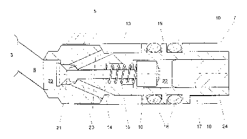
Figure 5a shows a sectional view of a pre-chamber gas valve 5. The
pre-chamber gas valve 5 can be fitted into a cavity 7 formed by a cylinder
head 2 (not shown here) or into a cavity 7 formed by a spark plug sleeve 4
(not shown here). The cavity 7 is therefore an opening which is provided
either in a cylinder head 2 directly or in a spark plug sleeve 4 and which can
accommodate a pre-chamber gas valve 5.
It is possible to clearly see the annular passage 13 formed between
the wall 10 of the cavity 7 and the outside contour of the pre-chamber gas
valve 5. The wall 10 can be formed either by the cylinder head 2 itself or
by a spark plug sleeve 4 fitted into the cylinder head 2. That possibility was
described by means of the embodiments shown in Figures 1 through 4.
The valve needle 14 is braced against its seat by the spring 15. The
cap 16 embraces the spring 15 and is connected to the valve needle 14 for
example by way of a beam welding.
The plug 17 closes and seals off the pre-chamber gas valve 5
upwardly. Sealing of the annular passage 13 with respect to the cavity 7 is
effected radially by way of the 0-rings 18. They are arranged in annular
receiving means formed by the projections 19. The sealing concept of the
pre-chamber gas valve 5 shown here therefore provides that sealing of the
pre-chamber gas valve 5 is effected radially, that is to say by way of the
outside surface of the pre-chamber gas valve 5.
Figure 5b shows a variant of Figure 5a in which the space 23 is of a
very substantially pear-shaped configuration narrowing towards the pre-
CA 02921627 2016-02-23
9
chamber 3. That configuration is particularly advantageous from the fluidic
point of view.
279351-9
List of references used:
1 internal combustion engine
2 cylinder head
5 3 pre-chamber
4 spark plug sleeve
5 pre-chamber gas valve
7 cavity
8 passage
10 9 flow transfer bore
10 wall of the cavity 7
11 spark plug bore
12 gas feed passage
13 annular passage
14 valve needle
15 valve spring
16 cap
17 plug
18 0-ring
19 projection
20 gas passage
21 lower cavity of the pre-chamber gas valve
22 upper cavity of the pre-chamber gas valve
23 space
24 valve body
Si axis of symmetry
S2 axis of symmetry
CA 2921627 2017-08-03