Note: Descriptions are shown in the official language in which they were submitted.
CA 02921788 2016-02-18
WO 2015/028544 PCT/EP2014/068243
1
[TITLE]
Container for explosive material
[FIELD OF THE INVENTION]
[BACKGROUND]
Explosive material, such as ammunition, detonators, munitions, dynamite,
explosives
etc. may be very useful in different situations. Explosives are often used in
mining op-
erations, ammunition is used in battlefields or for hunting purposes, and
often has to be
transported a long way from the manufacturer and to the location where the
explosive
material is to be used.
There are various requirements for the transport of explosive material,
depending on
the use of the material, the volatility of the material, the shelf life of the
material and so
on. For military ammunition, there are very strict guidelines on how
ammunition is sup-
posed to be handled, and there are various requirements for the transport
containers
for the ammunition, as the containers have to be capable of withstanding very
hostile
environments, and must be strong enough to protect the ammunition from
exploding,
should the container be dropped to a hard surface, such as the ground.
There are different requirements which an explosive material container has to
fulfil,
where different organisations, using the container may define the specific
requirements
which a specific container has to fulfil. The North Atlantic Treaty
Organisation (NATO)
has specific requirements to what kind of ammunition is used by its members,
and has
specified ammunition standards to which the member states and armies can
adhere to.
The purpose of such standards is that the ammunition is interchangeable, and a
coali-
tion of forces may use the same ammunition which can simplify logistics and
storage
requirements, as all the forces can use the same standard ammunition. This
also
means that NATO has also specific requirements for the containers which the
NATO
ammunition is to be transported and stored in. The ammunition containers have
to
have a specific size, both inside and outside, so that the container is easily
recogniza-
ble as holding a specific type of ammunition, and have a specified outer
dimension so
that the ammunition containers may be easily be stacked on pallets for bulk
transporta-
CA 02921788 2016-02-18
WO 2015/028544 PCT/EP2014/068243
2
tion. An example of such standardized ammunition containers is the M19A1
ammuni-
tion box for 7.62 x 51 mm NATO cartridges. Other types of ammunition
containers are
used for other types of standard NATO ammunition, where the size of the
container re-
flects the size of the ammunition.
In addition to the standardized size and design of the ammunition containers,
the con-
tainers used for NATO ammunition are required to withstand the extreme environ-
ments, to which the ammunition containers are supposed to be in, such as
extreme
colds and extreme heat and must be able to hold the ammunition in storage for
a mini-
mum of 20 years. In all these conditions the ammunition container must be in
working
order, so that the ammunition may be transported and accessed without any
hindrance.
The above requirements may be seen as the normal use requirements for a NATO
ammunition container, where there are further requirements for the container
that co-
vers extraordinary situations, such as if the container is damaged. The
container must
be capable of withstanding shocks or impacts within a predetermined range, in
order to
ensure that the container maintains its mechanical structure for holding and
transport-
ing the ammunition in case the container is damaged. The predefined range of
toler-
ance is for example that the container must be able to hold the ammunition, be
carried
via a handle, and be openable when a container filled with ammunition has been
dropped from at height of 12 meters to a hard surface, such as concrete, in a
cold envi-
ronment of - 47 C.
Such reliability of NATO ammunition containers has been achieved by providing
the
ammunition in containers that are made of steel, where the mechanical strength
of the
steel is not significantly affected by change in temperature, within a
predetermined
range from about - 47 C to 70 C, and is capable of being deployed in more
cold and
more heat should that be necessary. The steel casing of the container is also
highly re-
sistant to shocks or impacts, meaning that the structural integrity of the
container is
maintained even if the container is dropped from a significant height. The
steel may
bulge and be indented after the fall, but the steel construction is stable
enough to allow
the container to maintain its substantial shape, without falling apart, and
containing the
ammunition should such an accident happen. Furthermore, the steel container is
of
such a mechanical strength that it is capable of withstanding the stacking
ammunition
containers in large bulks on pallets for bulk transportation, where each
bottom contain-
CA 02921788 2016-02-18
WO 2015/028544 PCT/EP2014/068243
3
er in the stack may bear the weight of approximately 20 fully loaded
ammunition con-
tainers.
However, even though steel ammunition containers have been used since the
Second
World War (1940s) and have served its purpose fully, the steel construction of
an am-
munition container has a number of drawbacks. A steel container that is
capable of
withstanding all the forces required by NATO is made of a steel material that
is relative-
ly thick, resulting in an ammunition container that has a relatively high
weight compared
to the weight of the ammunition. This means that if ammunition is to be
transported in
bulk to a distant location of deployment, the transport to its final
destination is predomi-
nately done by air transport. Any form of air transport has a limit, where the
load carry-
ing capacity of the aircraft if often the limiting factor when the aircraft is
being loaded.
Thus, when ammunition is being transported in bulk, the weight of the
ammunition con-
tainers may be between 5-15% of the total weight of the bulk transport of the
ammuni-
tion. Thus, any reduction in weight of the ammunition container could save
weight for
the bulk transport, and a container weight reduction of approximately 50%
could allow
the aircraft to carry between 2,5 ¨ 7,5 % more ammunition in each transport
run. Such
reduction would reduce the logistics expenses by the military, as each
kilogram of
weight that has to be transported from one place to another has a cost.
Furthermore, even though the material cost of steel is currently relatively
low, the as-
sembly and construction of steel cases is relatively expensive, as the steel
panels have
to be formed into its shape and welded into its shape. This construction is
time con-
suming, either for skilled metal workers or robots that are performing the
construction
and assembly operations.
Thus, there is a necessity to provide a container for explosives that is
lightweight, inex-
pensive in production and is capable of meeting the minimum standards that are
re-
quired for use within the NATO alliance.
[GENERAL DESCRIPTION]
In accordance with the invention, there is provided a thermoplastic container
for explo-
sive material comprising: a primary part defining a rigid compartment for
holding explo-
sive material, where the primary part comprises: a side wall having an inner
periphery
CA 02921788 2016-02-18
WO 2015/028544 PCT/EP2014/068243
4
defining the side boundaries of the compartment and an outer periphery, a base
ar-
ranged at a lower end of the side wall defining the lower boundary of the
compartment,
where an upper end of the side wall is arranged to provide access to the
compartment
allowing explosive material to be loaded into the compartment; a secondary
part com-
prising: at least one reinforcement element defining an outer periphery of the
container,
wherein the reinforcement element is coupled to the primary part and is
adapted to
provide horizontal and/or vertical load support to the primary part and where
the rein-
forcement element comprises at least one collapsible impact zone adapted to
absorb
an external impact to the secondary part and to transmit the excess forces of
the im-
pact into from the reinforcement element to the primary part wherein the
container is
provided with a top part, that is adapted to selectively prevent access to the
compart-
ment wherein the top part is provided with cooperative top reinforcement
element that
extends the reinforcement element of the secondary part, from a lower end of
the top
part to an upper end of the top part, providing at least one second
collapsible impact
zone and providing horizontal and/or vertical load support from the upper end
of the top
part and to the lower end of the top part.
By providing the reinforcement element, it is possible to construct a
container for ex-
plosives made out of thermoplastic that is formed of a primary part that is,
on its own,
not capable of withstanding impacts or shocks that live up to the standard of
NATO
ammunition case standards. A problem with thermoplastic materials is that when
force
is applied to the thermoplastic material, if the force is high enough the
deformation that
occurs is in the form of irreversible plastic deformation that can seriously
diminish the
mechanical integrity of the material deformation. Furthermore, if the plastic
is a rigid
plastic, the deformation may be in the form of breakage of the material, where
cracks,
fractures, splinters, shattering or even complete disintegration can occur,
especially in
cold conditions as the rigidness prevents the thermoplastic material to deform
beyond a
certain level. Such problems may be solved in the simplest manner by
increasing the
thickness of the material, so that the impact may be absorbed by more
material. Thus,
the thickness of the material may be increased up to a point to where the
thermoplastic
material is capable of withstanding the required impact or shock. This method
of solv-
ing the durability of the thermoplastic material means that the increase in
material
thickness results in an increased weight of the material, which means that the
ad-
vantage of a constructing from a lightweight material has vanished.
CA 02921788 2016-02-18
WO 2015/028544 PCT/EP2014/068243
Thus, an aspect of the present invention, is that the plastic container is
provided with at
least one area, in the form of a secondary part placed on the outside of the
primary
container with is specifically designed to give structural integrity to the
primary part and
furthermore to absorb an impact to the thermoplastic container. By providing a
rein-
5 forcement part on certain parts of the container it is possible to
reinforce the primary
part in selective areas that are more likely than others to be the object of
an impact or
shock, without adding reinforcement material to the primary part in areas that
are not
likely to be affected by an impact or shock in general usage of the container.
The reinforcement element may be added to the outer surface of the primary
part, in
areas that are most likely to be the first point of contact when the box is
dropped on a
flat surface. Such exposed areas may e.g. be the corners and joining of side
walls,
should the container be of a rectangular shape, having four sides walls, a
bottom wall
and a top wall, where the side walls are joined and the bottom and top walls
are joined
to the side walls. The reinforcement element may be positioned to overlap the
exposed
area of the primary container, providing an impact zone, where the impact zone
is
adapted to be capable of withstanding the impact that would otherwise affect
the ex-
posed area. This means that when an impact is directed towards the exposed
area, the
impact reinforcement element becomes the first point of contact, and the
impact zone
absorbs the force of the impact and transmits the excess force (force not
absorbed by
the impact zone) to areas of the primary part that are distant from the
exposed part,
and thereby distributing the force of the impact to a much larger area of the
primary
part allowing the force to be absorbed in the primary part without risking a
plastic de-
formation of the primary part. Thus, reducing the risk that the energy of the
impact will
be concentrated in a small concentrated area of the outer periphery of the
primary part.
The impact zone of the reinforcement element, which is adapted to protect the
exposed
area of the primary part, may be adapted to absorb the impact by allowing
parts of, or
the entire impact zone to deform should the impact be of a force that is above
a prede-
fined amount. Thus, at least a part of the kinetic energy transferred via the
impact is
absorbed by the impact zone causing a deformation of the impact zone, while
any ex-
cess kinetic energy, not absorbed by the deformation, may be transferred away
from
the exposed area of the primary part. Thus, by providing a reinforcement
element that
is capable of deforming and transferring the kinetic energy away from the
exposed ar-
ea, it is ensured that the exposed area is protected by the reinforcement
element and
CA 02921788 2016-02-18
WO 2015/028544 PCT/EP2014/068243
6
ensuring that the exposed area of the primary part will not rupture when
during an im-
pact. Thus, it is ensured that the contents of the container will remain
inside the con-
tainer, and will not be capable of exiting the container via the area of the
container
which has suffered the impact. This effectively means that the container may
be pro-
vided with impact zones that are designed to deform in a controlled manner,
ensuring
that the deformation does not damage holding compartment of the container and
en-
suring that the content holding function of the container is intact.
Furthermore, as only selective exposed areas of the container are provided
with rein-
forcement elements, and not all the outer surfaces of the primary part, it is
possible to
provide a container for explosive material that is lightweight. Thus, areas
that are not
likely to be affected by an impact, e.g. when the container is dropped onto a
flat sur-
face, may have a reduced material thickness and/or density, while exposed
areas of
the container may be provided with protective zones. Thus, the container in
accord-
ance with the invention may be provided in lightweight thermoplastic material,
where
vulnerable areas of the container may be provided with one or more area that
is rein-
forced to withstand an impact.
In one embodiment the reinforcement element may be adapted to provide
horizontal
and/or vertical load support to the primary part. The primary part may be of a
thermo-
plastic material, which may have a predefined compressive strength, allowing
the pri-
mary part to withstand a certain load. However, for an ammunition container
adapted to
withstand the rigorous NATO standards must be capable of carrying a load that
is up to
20 times its own loaded weight (filled with ammunition) and where the
container must
be capable of carrying the load for approximately 20 years in storage. The
thermo-
plastic material may be chosen as an alternative to steel as a lightweight
material, it is
advantageous to provide horizontal and/or vertical load support to the primary
part in at
least the one area where the reinforcement member is provided. Thus it is
possible to
add load support to the inner part in discrete areas, and thereby ensuring
that the pri-
mary part is prevented from collapsing under the load when up to 20 times the
weight
of the loaded container is stacked on top of the container. This ensures that
the con-
tamer may be stored and transported in bulk, where a number of containers are
stacked onto a pallet, to make bulk transport easier.
CA 02921788 2016-02-18
WO 2015/028544 PCT/EP2014/068243
7
In one embodiment the reinforcement element may extend from the lower end of
the
side wall to the upper end of the side wall. The reinforcement element may be
provided
at least one part of the side wall of the primary part, and where the
reinforcement ele-
ment provides a load support to the primary part along the entire height of
the side wall
and/or where the reinforcement element provides a protection to an area on the
outer
periphery that extends the entire horizontal length (height) of the side wall.
This means
that the side wall, in the area of the reinforcement element, will be capable
of bearing
an increased load compared to an area of side wall that does not have a
reinforcement
element. Alternatively, the reinforcement element can be provided in such a
manner
that the reinforcement element off loads a part of the horizontal and/or
vertical load ap-
plied to the top of the container, so that the horizontal and/or vertical load
is distributed
between the side wall of the primary part and the reinforcement element.
Alternatively,
the reinforcement element may both provide an increased load support to the
side wall
and offload the side wall, i.e. in combination.
As the reinforcement element may extend along at least the entire horizontal
length of
the side wall, the reinforcement element may protect an exposed area of the
side wall
along the entire height of the side wall. Such an area may, as an example be a
bend
along the side wall, where the side wall on one side of the bend is
substantially per-
pendicular to the side wall on the opposite side of the side wall. I.e. in a
corner area of
the primary part, as the corner is an exposed area of the primary part. Thus,
the rein-
forcement element may overlap the outer corner area of the primary part, so if
the an
impact is directed towards the corner area, the reinforcement area will
receive the im-
pact, and ensure that the energy is absorbed in the impact zone and/or
directed to-
wards another area of the primary part.
In one embodiment the first end of the reinforcement element may be attached
to a first
area of the primary part and a second end of the reinforcement element is
attached to
a second area of the primary part that is distant to the first area along the
length of the
side wall of the primary part. This means that the reinforcement element may
be cou-
pled in two different positions to the primary part, so that when the
reinforcement ele-
ment is exposed to an impact directed towards an exposed area of the primary
part,
the reinforcement element will transmit the energy of the impact to at least
two different
positions on the primary part, and thereby minimizing the risk that the
primary part will
be compromised or opened via the exposed area, ensuring that the content of
the pri-
CA 02921788 2016-02-18
WO 2015/028544 PCT/EP2014/068243
8
mary part will remain inside the primary part subsequent to the impact and
will not es-
cape via an impact damage to the exposed part. By attaching the reinforcement
ele-
ment in two different positions, the kinetic energy of an impact will be
distributed to a
larger area of the primary part than if the reinforcement element is only
attached in a
single position.
Within the meaning of the present invention, the length of the side wall of
the primary
part may be seen as the circumference of the side wall when the side wall is
seen from
above or below. The circumference may be measured along the length of the side
walls, where the length is vertical and is perpendicular to the horizontal
height of the
side wall, and the direction of thickness of the side wall.
In one embodiment, the first area of the primary part may be arranged on an
end side
wall of the primary part and the second area of the primary part is arranged
on a longi-
tudinal side wall of the primary part. This means that he reinforcement
element may ex-
tend from an end side wall and across a corner of the primary part to a
longitudinal side
wall, ensuring that the reinforcement element overlaps the entire corner of
the primary
part across the length of the side wall. Thus the exposed part, i.e. the
corner, which
may be an exposed part of the primary part is protected by the reinforcement
element,
ensuring that any impact that is directed towards the overlapped corner is
received by
the reinforcement element. Furthermore, in case the reinforcement element is
exposed
to an impact, the kinetic energy of the impact is transferred to two different
areas of the
side wall, and where the reinforcement element transfers the energy in at
least two dif-
ferent directions, when the end side wall and the longitudinal side wall are
at an angle
to one another, such as if the side walls are substantially perpendicular to
each other.
Thus, the energy of the impact is distributed to two different parts of the
primary part,
and thereby reducing the risk that the constructional integrity of the primary
part is
compromised.
In one embodiment, the collapsible impact zone of the reinforcement element
may be
elevated away from outer periphery of the side wall, so that an overlapping
area of the
impact zone is mechanically independent from an exposed area of the outer
periphery.
The direction of elevation may be substantially normal to the outer periphery
of the pri-
mary part, so that there is a distance between the reinforcement element and
the ex-
posed area of the primary part. Thus, if the impact zone is exposed to an
impact, there
CA 02921788 2016-02-18
WO 2015/028544 PCT/EP2014/068243
9
is a reduced risk that the reinforcement element will transfer the energy of
the impact
into the exposed area in a direction that is normal to the outer periphery.
The rein-
forcement element will transfer the kinetic energy of the impact to a
different area of the
primary part, reducing the risk that the energy of the impact will be
concentrated in a
small concentrated area of the outer periphery of the primary part.
In one embodiment, the collapsible impact zone may be arranged to overlap a
transi-
tional area of the side wall where a longitudinal side wall joins an end side
wall, where
the longitudinal side wall joins the base of the primary part and/or where the
base wall
joins the end side wall. Thus, the impact zone of the reinforcement element
may be ar-
ranged on the outer periphery of the primary part in such a manner that a
transitional
area, such as a corner joining two or three sides of a primary part is covered
by an im-
pact zone. The transitional areas, or corners, of a rectangular primary part
are the are-
as that are have the most risk of being exposed to an impact, as it is highly
unlikely that
a container will be dropped onto a flat surface, where the plane of a side
wall, bottom
wall or a top wall will be 100% parallel to the flat surface. Thus, a
transitional area may
be seen as the part of the primary part that is most likely to be exposed to
an impact.
Thus, by ensuring that an exposed area of the primary part is overlapped with
a rein-
forcement element, and thereby having an impact zone that is adapted to absorb
and
transfer the energy of the impact away from the exposed area, reduces the risk
that the
exposed part will be damaged after the impact.
In one embodiment, the upper end of the side wall may be provided with a
flange ex-
tending along the upper end of the side wall. The upper end of the side wall
may be
provided with a flange that extends along the entire upper area of the side
wall, extend-
ing an opening into the container above the limit of the side wall. The flange
may be of
the same material as the side wall, having the same thickness and the same
shape,
where the flange may be adapted be received in a top part, or a lid, that is
adapted to
close the compartment from the outside. Thus the flange may be adapted to
provide an
edge to which a sealing in the top part will cooperate with, so that the lid
may be sealed
hermetically and/or liquid tight to the primary part.
In one embodiment, the container may be provided with a top part that is
adapted to
selectively prevent access to the compartment. The top part may be seen as a
lid onto
the container, so that the container may be closed during transport and/or
storage. The
CA 02921788 2016-02-18
WO 2015/028544 PCT/EP2014/068243
lid ensures that external elements, such as dirt do not enter the compartment
when the
lid is closed, and also ensures that the contents of the compartment are
securely main-
tained inside the compartment while the top part is secured to the primary
part or the
container.
5 In one embodiment, the top part may have a groove that cooperates with
the flange of
the side wall. The groove may be positioned and sized in such a way that when
the top
part is closed, the bottom of the groove is substantially flushed with a top
of the flange.
In one embodiment, the entire bottom of the groove can be flushed with the
entire top
of the flange, ensuring that the closure is even along the entire groove.
10 In one embodiment, the groove may be provided with a sealing element.
The sealing
element may be arranged to minimize the risk that liquids, vapour, dirt
particles or gas-
ses may enter the compartment, when the top part is closed. The sealing may
have a
further functionality, in that the sealing may be provided between inner
surface of the
lid and the top surface of the flange. Thus, if the lid is exposed to an
impact, the sealing
may be adapted to absorb a part of the kinetic energy of the impact, reducing
the risk
that the kinetic energy will damage the flange and/or the side wall of the
primary part.
Such a sealing may be an elastic seal that is capable of absorbing kinetic
energy, e.g.
a rubber seal, where the thickness of the sealing has an impact on its
absorbing capa-
bilities.
In one embodiment the top part may be provided with a handle. The handle may
be
used by a person to transport the container from a first position to a second
position us-
ing the hand.
In one embodiment the top part may be provided with a handle that is offset in
its
parked position from an upper edge of the top part in a direction towards the
compart-
ment of the container. This ensures that if the container is dropped on a flat
surface,
the handle will not be an initial point of contact of the impact, reducing the
risk that the
handle will be damaged during the impact. This increases the likelihood that
the handle
may be used to carry the container away after an impact has damaged the
container,
and where the handle is securely fastened to the top part.
CA 02921788 2016-02-18
WO 2015/028544 PCT/EP2014/068243
11
In one embodiment, the top part may be provided with cooperative top
reinforcement
element that extends the reinforcement element of the secondary part, from a
lower
end of the top part to an upper end of the top part, providing at least one
second col-
lapsible impact zone and providing horizontal and/or vertical load support
from the up-
per end of the top part and to the lower end of the top part. The top part of
the contain-
er may have a size and a shape that corresponds with the primary part, i.e.
for a rec-
tangular compartment, the shape of the top part will most likely be
rectangular as well,.
Thus, the top part is provided with corners or junctions between side parts
and/or the
top wall of the top part, which may be seen as exposed parts of the top part.
Thus, in
order to ensure that the exposed areas of the top part that are likely to be
the initial
point of contact when the closed container is dropped, may be provided with
reinforce-
ment elements to absorb the energy of the impact and to transmit the kinetic
energy of
the impact to a different part of the top part, thereby reducing the risk that
the impact
will damage the top part in such a way that the constructional integrity of
the top part is
significantly compromised.
The reinforcement element on the top part may be constructed in similar or the
same
ways as the reinforcement element of the primary part, and any feature and/or
ad-
vantage of one of the reinforcement elements may be equally applied to the
other.
Furthermore, the top reinforcement element may be used to transfer a load
support
from the lid and towards the reinforcement element and/or the side wall and
thereby in-
creasing the load bearing capabilities of the top part and the side walls,
ensuring that
the closed container is capable of carrying a load that is up to 20 times its
own loaded
weight (filled with ammunition) and where the is capable of carrying the load
for ap-
proximately 20 years in storage.
In one embodiment, the container may be provided with a plurality of
reinforcement el-
ements of the secondary part that are elevated from the outer peripheries of
the prima-
ry part, increasing the likelihood that the secondary part is the initial
point of contact
when the container comes into contact with a flat surface. The reinforcement
elements
may have an outer circumference that is greater than the outer circumference
of the
primary part, so that the impact is firstly exposed to the reinforcement
element, allowing
the energy of the impact to be absorbed and transferred to a different part of
the prima-
ry part. The reinforcement elements may be provided at the peripheries of the
walls of
CA 02921788 2016-02-18
WO 2015/028544 PCT/EP2014/068243
12
the container and/or the top part, so ensuring that the initial energy of the
impact is
transferred from the surface and to the reinforcement element.
In one embodiment the reinforcement element may extend from the upper end of
the
side wall and towards the lower end of the side wall and terminating before it
reaches
the lower end of the side wall
In one embodiment the side wall may be provided with a reinforcement beam that
ex-
tends from a lower end of the reinforcement element to the lower end of the
side wall.
In one embodiment the base may be provided with a plurality diagonal
reinforcement
beams.
In one embodiment the reinforcement element may be provided with a handle.
In one embodiment the reinforcement element may define a volume between the
side
boundary of the compartment and an inner boundary of the reinforcement element
The container according to the invention, may be produced of a thermoplastic
material,
that allows the container to be injection and/or blow moulded, ensuring that
the con-
tamer may be produced at a low cost.
The container according to the invention, even though it is primarily
disclosed for use
with military ammunition, may be used as a container for any kind of explosive
material
that has to be transported and needs to be protected during transport and/or
during
storage.
The primary part and the secondary part may be at least partly constructed
from ther-
moplastic materials. In another embodiment, the primary part and/or the
secondary part
may be entirely constructed from thermoplastic materials.
[BRIEF DESCRIPTION OF DRAWINGS]
The invention is explained in detail below with reference to the drawings, in
which
CA 02921788 2016-02-18
WO 2015/028544 PCT/EP2014/068243
13
Fig. 1 shows an exploded perspective view of a container in accordance with
the inven-
tion,
Fig. 2 shows a perspective view of a closed container in accordance with the
invention,
Fig. 3 shows a cross sectional view of the casing part of Fig. 2 taken along
axis III-Ill,
Fig. 4 shows a cross sectional view of the casing part of Fig. 2 container
taken along
axis IV-IV,
Fig. 5 is a perspective view of an alternative embodiment of a container in
accordance
with the invention shown from the front,
Fig 6 is a perspective view of the container shown in Fig. 5 shown from the
back,
Fig. 7 is an exploded view of the container shown in Fig. 5 and 6,
Fig. 8 is an end view the container shown in Fig. 5, and
Fig. 9 is a top view of the inner surface of the bottom of a casing part 2 in
accordance
with the invention.
In the following detailed description of the figures, reference numbers
relating to similar
parts or elements will be utilized for the same parts or elements in all the
embodiments
shown unless otherwise stated.
[DETAILED DESCRIPTION OF DRAWINGS]
Fig. 1 shows a container 1 in accordance with the invention, where the
container 1
comprises a casing part 2 and a lid part 3. The lid part 3 is adapted to close
the casing
part 2, in order to enclose the compartment 4 of the casing part 2.
The casing part 2 comprises a primary part 5, which has an inner periphery 6
that de-
fines the compartment 4 of the casing part 2, and an outer periphery that
defines an
outer periphery 7 of the compartment 4. In this exemplary embodiment the
compart-
ment is shown as substantially rectangular. The primary part 5 comprises a
side wall
CA 02921788 2016-02-18
WO 2015/028544 PCT/EP2014/068243
14
that may extend to four sides of the wall in a longitudinal side wall 8 and an
end side
wall 9, where the longitudinal and the end side walls have opposing end walls
(not
shown). The side walls have a lower edge 10 defining a bottom part of the
compart-
ment 4 and an upper edge 11 defining the upper part of the compartment 4,
where the
height of the side wall defines the loading volume of the compartment 4. The
side walls
8, 9 are provided with a flange 12 that extends along the upper edge 11 of the
com-
partment 4, where the upper edge is designed to embed into the lid part 3,
when the lid
part is closed, as seen in Fig. 3. The upper part may further have a first
part 13 of a
hinge, where the second part 14 is attached to the lid part 3. The hinge 13,
14 ensures
that the lid may be rotated along an axis defined by the hinge, in order to
open and
close the lid part 3 onto the casing part 2 of the container 1.
Thus, when the lid is closed, the flange 12 is inserted into the volume of the
lid part 3,
so that the side wall 15 of the lid part 3 overlaps the flange 12 so that the
flange 12 is
hidden from view when the lid is closed.
The primary part 5 of the casing part 2 of this embodiment is provided with at
least four
reinforcement elements 16, 17, 18, 19 that are arranged on the outer periphery
7 of the
primary parts. The reinforcement elements 16, 17 ,18 ,19 are arranged to
overlap the
exposed parts, e.g. the corners (20, 21, 22, 23 as shown in Fig. 3) of the
primary part
5, so that if an impact is directed towards the exposed parts of the primary
part 5, the
reinforcement elements 16, 17, 18, 19 will intersect the impact before the
energy of the
impact can come into contact with the exposed areas. The reinforcement
elements 16,
17, 18, 19 may be designed as weakened areas that are designed to collapse or
break,
in order to absorb an impact that is directed towards the exposed areas. Thus
the rein-
forcement elements 16, 17,18, 19 are capable of absorbing any impact that may
be
applied to the primary part 5, and minimize the risk that the exposed areas,
that define
the outer periphery of the compartment 5, are damaged by the impact.
The lid part 3 may be provided with corresponding reinforcement elements 24,
25, 26
are adapted to protect the corners 27 of the flange, and to increase the
strength of the
lid part 3. The reinforcement elements are capable of absorbing any impact
that may
be applied to the lid part, minimizing the risk that the flange 12 is damage
and/or that
the structural integrity of the lid part 3 is compromised, so that the lid
will remain in a
closed state on the container if an impact is directed towards the lid part.
CA 02921788 2016-02-18
WO 2015/028544 PCT/EP2014/068243
The reinforcement elements 16, 17, 18, 19 may also be function as an element
provid-
ing horizontal and/or vertical load bearing capabilities to the primary part
5, so that
when a load is applied to the primary part, via the lid part 3 or the flange
part 12, the
primary part will be able to withstand the load and reducing the risk that the
structural
5 integrity side walls 8,9 of the primary part will be compromised, causing
the side wall
8,9 to collapse or be damaged by the load. The reinforcement elements 16, 17,
18, 19
may be used to offload a part of the load from the side walls of the primary
parts and/or
by providing extra strength to the primary part, and improving the rigidity of
the side
wall, e.g. to prevent the side wall from bulging from its original shape when
a load is
10 applied to the primary part. As the flange 12 of the primary part is
adapted to be insert-
ed into the lid part 3, providing a seal between the lid part and the flange,
any load that
is applied to the lid part 3, e.g. during stacking of multiple containers 1,
may be trans-
ferred into the flange part and onwards towards the side walls 8,9 of the
primary part 5.
In order to increase the load bearing capabilities of the container, when the
lid part 3
15 closes the compartment 6, the lower edge 37 of the reinforcement
elements 24, 25, 26
of the lid part may be adapted to abut an upper edge 38 of the reinforcement
elements
16, 17, 18, 19 of the primary parts. This means that when a load and/or an
impact is
applied to the lid part 3, the energy of the load or impact may be transferred
from the lid
part 3 to the reinforcement elements 16, 17, 18, 19 of the primary part,
ensuring that
the energy is transferred between the two parts 2, 3, and thereby reducing the
risk that
the energy will be concentrated enough in a small area causing the container 1
to be
compromised.
The reinforcement elements 16, 17, 18, 19 are applied to the outer periphery
of the
primary part 5, which means that in the areas where the reinforcement elements
areas
are provided, the total thickness of the wall is larger than the thickness of
the side walls
8,9 having no reinforcement elements. This means that the outer surface 28 of
the rein-
forcement elements 16, 17, 18, 19 is the outermost periphery of the primary
part, en-
suring when the container 1 is dropped on a flat surface, the initial point of
contact with
the flat surface is the reinforcement element. Thus, it is prevented that when
dropped,
the impact will damage the non-reinforced parts of the primary part 5, i.e.
the recessed
parts of the outer periphery of the casing.
The lid part 3 and the casing part 2 are provided with means for locking the
lid part 3 in
its closed position on the casing part 2. The means may be in the form of a
latching
CA 02921788 2016-02-18
WO 2015/028544 PCT/EP2014/068243
16
mechanism 29, which is adapted to be attached to a fastener 30 on the end side
wall 9
of the primary part. The latching mechanism 29 may be in the form of a draw
latch 31,
having a loop 32 that is adapted to interact with a fastener 33 on the lid
part 3. The
draw latch 31 may be closed, so that the loop holds the lid part tightly
attached to the
casing part, where the hinge 13, 14 holds the opposite end of the lid part 3
in contact
with the casing part 2. The draw latch 31, loop 32, and the fasteners 30, 33,
may be
made of a thermoplastic material. By positioning the latching mechanism 29 may
be
positioned in the recessed part of the casing part 3, so that the outermost
part of the
latching mechanism does not extend beyond the outer surface 28 of the
reinforcement
part, ensuring that any impact with a flat surface will have its initial
contact with the re-
inforcement element, and thereby protecting the latching mechanism.
Furthermore, the lid part 3 may be provided with a handle 34, where the
handle, similar
to the latching mechanism 29, is arranged in its parked position in an area 35
that is
recessed in relation to the top surface 36 of the lid part 3. Thus, if the
container 1 is
dropped on the lid part 3, the handle will not be the initial contact of the
impact, ensur-
ing that the handle is intact when retrieving the container 1 after the
impact.
The positioning of the handle 34 and the latching mechanism 29 in their
recessed are-
as is shown in Fig. 2.
When an impact hits the container 1, having the reinforcement elements 16, 17,
18, 19,
24, 25, 26 as the initial point of contact, the reinforcement elements may be
adapted to
collapse in a controlled manner, so that the a part of the kinetic energy of
the impact is
absorbed by the collapse. The remaining part of the kinetic energy may be
transmitted
to other parts of the primary part, ensuring that the energy is distributed to
a large area
and reducing the risk of damage to the primary part 5. In this example the
reinforce-
ment element 18 is attached to the longitudinal side wall 7 of the primary
part 5, via a
transitional area 39. Thus when an impact reaches the outer surface 28 of the
rein-
forcement element 18, the kinetic energy is absorbed by the reinforcement
element
and transmitted via the transitional area 39 to the longitudinal side wall 7
of the primary
part 5. As the transitional area 39 extends from the upper edge 11 of the side
wall to-
wards the lower edge 10 of the side wall, the energy may be transferred to a
large area
or volume of the primary part 5. Furthermore, the primary part may be provided
with re-
inforcement beams 40, 41 that extend along the longitudinal length of the side
wall 7,
CA 02921788 2016-02-18
WO 2015/028544 PCT/EP2014/068243
17
which are in mechanical communication with the reinforcement elements of the
primary
part 5. The reinforcement beams 40, 41 allow the kinetic energy to be
transmitted to
other parts of the primary part 5, allowing the kinetic energy to be
transmitted to an
even larger area of the primary part. The reinforcement beams 40, 41 may also
be
used to provide strength to the side wall 7 in a direction that is parallel to
the reinforce-
ment beam, and reducing the risk of the side wall 7 collapsing in the
longitudinal direc-
tion.
The top surface 36 of the lid may be provided with a plurality of plugs 42,
that extend
beyond the top surface of the lid, where the plugs may be adapted to interact
with a
plurality of cooperating sockets (not shown) that are positioned on the bottom
surface
of the casing part. Thus, when a container 1 is positioned on top of another
container,
the plug 42 and sockets will line up and connect, increasing the lateral
stability of the
stack, as the plugs 42 and sockets ensure that the two containers cannot
displace
sideward with regards to one another. The plugs may also be positioned in such
a way,
that one container may be positioned on top of two containers that are
positioned ap-
proximately perpendicular to the upper container, allowing a crossed stacking
of the
containers and ensuring that the plugs are lined up with the sockets of the
correspond-
ing container.
For a crossed stacking it may be advantageous that the proportional size of
the con-
tamer is approximately 2:1 where the length of the container is approximately
two times
the width of the container. This allows two containers to be cross stacked on
top of a
single container where the half of the length of the upper container overlaps
the width
of the lower container, or vice versa.
Fig. 2 shows the container in accordance with the invention where the lid part
3 and the
casing part 2 have been assembled. Furthermore, the handle 34 and the latching
mechanism 29 have been introduced onto the container 1. The reference numerals
shown in Fig. 1 may be applied to Fig. 2.
The lid part 3 has been introduced to close the compartment 4, where the lower
edge
37 of the reinforcement elements 24, 25, 26 abuts the upper edge of the
reinforcement
elements 16,17,18,19, creating a mechanical connection between the
reinforcement
CA 02921788 2016-02-18
WO 2015/028544 PCT/EP2014/068243
18
elements of the lid part 3 and the casing part 2, allowing kinetic energy to
be transmit-
ted from the lid part 3 and into the casing part 2.
The handle 34 may be seen as being in it parked position within the
circumference
outermost surface 36 of the top part 3. When the handle 34 is grabbed, the
ends 43, 44
of the handle 34 allow the handle 34 to extend upwards and extending out of
the re-
cess 35 so that the handle may be accessed, similar to the handle of a wine
box. The
ends are loosely attached to the lid part, and have a margin of movement,
allowing the
length of the handle 34 between the handle sockets 45, 46 to become longer.
When
the handle is released, it may return to its parked position, inside the
recess 35, due to
e.g. the mechanical memory of the handle. I.e. any deformation to the material
during
the grabbing of the handle 34 may be reversible. The handle 34 may be made out
of
rubber, or any thermoplastic material.
Fig. 3 shows a cross sectional diagram taken along axis III-Ill of Fig. 2,
where the cas-
ing part 2 is seen from above. The side walls 7 7', 9, 9' of the primary part
5, are joined
or are transitioned in corner sections, 20, 21, 22, 23, that may be seen as
exposed
parts of the primary part 5. The exposed areas may be seen as the areas that
have a
high risk of being exposed to impact, when the container 1 is dropped onto a
flat sur-
face. Thus the corner areas 20, 21, 22, 23 and parts of the side walls 7, 7',
9, 9' are
provided with reinforcement members 16, 17, 18, 19, that prevent the impact in
coming
into direct contact with the corner areas. This may be done in different ways,
i.e. by in-
troducing an increased material thickness in the exposed areas, but in this
example,
the reinforcement members are elevated in a direction away from the corner
areas.
This means that the corners are surrounded by open space 47, 48, 49, 50, which
al-
lows the reinforcement members to collapse and/or crumble in a controlled
manner,
without the reinforcement member coming into direct contact with the corner
area.
Thus, the reinforcement member may absorb part of the impact, and as the
reinforce-
ment members are attached at a first 54 and a second end 55, in this view, to
the pri-
mary part 5, the kinetic energy of the impact may be transferred from the
reinforcement
element 16, 17, 18, 19 and to the side walls 7, 7', 9, 9' of the primary
parts, ensuring
that the kinetic energy is distributed to different parts of the primary part
5.
Fig. 3 further shows the bottom wall 51 of the container of the casing part 2,
where the
bottom wall may be provided with one or more absorption zones 52 where the
bottom
CA 02921788 2016-02-18
WO 2015/028544 PCT/EP2014/068243
19
part has been weakened, as shown in Fig. 4. These zones 52 may have a material
thickness that is less than the abutting zones 53, so that if a container
filled with a
mass in form of explosive material, such as ammunition, is dropped the
absorption
zones 52 are adapted to deform, by stretching or extending, so that the impact
of the
mass will be absorbed by the absorption zones 52. Thus, the abutting zones 53
will
maintain their mechanical structure, while the absorption zones are allowed to
deform
in a controlled manner. The thickness of the material depends on the material
proper-
ties, such as elasticity, density, etc. but the a correct thickness of the
absorption zone
52 and the abutting zone 53 may be chosen based on the mass of the material
that is
supposed to be loaded into the container 1. The absorption zones may
alternatively be
made out of a different material than the abutting zones to allow controlled
deformation
of the zones.
Fig. 4 shows a cross sectional view of the casing part 2, taken along axis IV-
IV of Fig.
2, where the reference numbers of the previous Figs. applies to Fig. 4. The
bottom wall
51 of the casing part 2, may here be seen as having areas that have a reduced
thick-
ness, or absorption zones 52, compared to the abutting zones 53. This means
that
when a mass 56 is travelling in a downwards direction A, the absorption zones
are ca-
pable of absorbing the kinetic energy of the mass 56 by stretching laterally
in the direc-
tions of arrow B, where the thicker areas may maintain their shape and/or
mechanical
integrity, and ensuring that he mass is not capable of exiting compartment 4
via the
bottom wall, when the impact is within the tolerated standards.
Furthermore, it may be seen in Fig. 4, that if the reinforcement element 18
has a height
that corresponds with the height of the side wall 7, the bottom corner 57 of
the rein-
forcement element is capable will receive any impact that is directed toward
the bottom
corner 58 of the side wall 7. Thus the reinforcement elements 16,17,18,19
ensure that
an impact from a flat surface will always come into contact with the
reinforcement ele-
ment first and not the exposed areas of the primary part. In this view, the
lid has not
been placed on the flange 12, so that the flange is exposed. However, during
use,
when the container 1 is supposed to carry explosive material, the lid will be
closed, and
the flange 12 will not be exposed to an impact.
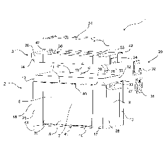
Fig. 5 is a perspective view of an alternative embodiment of a container 100
having a
casing part 2 and a top part 3. The casing part 2 comprises a primary part
(not shown)
CA 02921788 2016-02-18
WO 2015/028544 PCT/EP2014/068243
which has an inner periphery that defines the compartment of the casing part
and an
outer periphery 7 of the compartment, similar to that shown in the embodiment
shown
in Fig. 1 and 2.
The container 100 differs though from the container 1 shown in Fig. 1 in that
the rein-
5 forcement elements 116, 117, 118 overlap the corners of the casing 2, and
extend from
the top where the reinforcement elements 116, 117, 118 having the impact zones
abut
the top part and downwards where the lower parts 120, 121, 122 of the
reinforcement
elements 116, 117, 118 terminates before it reaches the vertical end 124 of
the casing
2. The area of the casing below the reinforcement elements 116, 117, 118,
between
10 the lower parts and the vertical end of the casing, may be provided with
reinforcement
means 125, e.g. in the form of reinforcement beams 125, that provide the parts
of the
casing 2 that is not provided with a reinforcement element with an increased
rigidity
both in horizontal and vertical directions. Thus when the container 100 may be
stacked,
the reinforcement beams may transfer vertical forces downwards from the
reinforce-
15 ment elements and prevent the casing from being compromised when a
significant load
is placed on top of the container 100 during stacking. Furthermore, the
reinforcement
beams may provide a horizontal reinforcement, so that the contents casing 2 is
pre-
vented from bulging out when it is filled with e.g. ammunition or when a load
is posi-
tioned onto the top part during stacking, or even when the users use the
container for
20 sitting. Thus the reinforcement beams 125 and the reinforcement elements
116, 117,
118 may collectively transmit loads from the top of the container 100 towards
the bot-
tom of the container, reducing the risk that the primary part may be
compromised dur-
ing its normal use.
The reinforcement elements 116, 117, and 118, in the areas covering the front
end 126
and the back end 150 (shown in Fig. 6) may be hollow, i.e. where the
reinforcement el-
ements 116, 117, 118, create a volume between the outer periphery 7 of the
casing 2
and an inner surface of the reinforcement elements 116, 117, 118, similar to
the vol-
umes 47, 48, 49, 50 shown in Fig. 3. The reinforcement elements may be open in
the
upper boundary, allowing a first latching mechanism 127 to be introduced into
the vol-
ume and extend from one reinforcement element 116 to the opposite
reinforcement el-
ement 117. The first latching mechanism 127 provides a base for a clasp 128,
which
may be rotationally coupled to the first latching mechanism at a first end
129, so that
the clasp 128 may be moved from a closed position where the second end 130 of
the
CA 02921788 2016-02-18
WO 2015/028544 PCT/EP2014/068243
21
clasp 128 is coupled to the top part 3, and fixes the top part 3 in a position
where the
top part prevents access to the compartment of the casing part 2, to an open
position,
where the second end 130 of the clasp 128 is moved away from the top part,
allowing
the top part 3 to be released from the casing part 2.
Furthermore, the volume of the reinforcement elements may further be utilized
to fix a
front handle 131 to the casing part 2, where the front handle 131 extends from
within
the volume of one of the reinforcement element 116 and across the first end
129 hori-
zontally and into the volume of the opposite reinforcement element 117. The
rein-
forcement element may be provided with an opening 132 that allows the front
handle
131 to exit from the volume, where the opening 132 may be dimensioned to be
smaller
than an end part of the front handle 131, so that the end part is prevented
from exiting
the opening in a horizontal direction when a force is applied to the front
handle 131.
Fig 6 is a perspective view of the container 100, showing the back end 130 of
the con-
tainer 100, and the opposing reinforcement elements 118, 119, covering the
corners of
the casing 2. The reinforcement elements 118, 119 may define a volume, where
the
volume may be open from the upper periphery 133 of the reinforcement elements
118,
119, allowing access to the volume from the upper periphery 133. The container
100
may be provided with a first hinge element 136, that is adapted to extend into
the vol-
ume of the reinforcement element 118, where a lower end of the hinge element
136
(not shown) is adapted to reside inside the volume, and the upper end 137 is
adapted
to extend above the upper periphery 133 and provide a rotational coupling to
the top
part 3. Thus the top part 3 may be opened and closed by a rotational movement
where
the front end of the top part 3 may be fixed using the clasp 128 shown in Fig.
5 and the
back part of the top part 3 may be rotationally coupled to the casing part 2,
via the first
hinge element 136. Thus, when the clasp is in its open position the front end
of the top
part 3 may be lifted in a direction from the casing part 2, where the back end
of the top
part 3 maintains its rotational coupling with the casing via the hinge
element. The top
part 3may either be adapted to have an integrated second hinge element 138,
that may
be moulded into the top part 3 or have a second hinge element 138 that is
releasably
attached to the top part 3, as shown in Fig. 7. The hinge elements 136, 138,
may be
adapted to transmit loads from the top part3 to the casing part 2, when load
is placed
on top of the container 100.
CA 02921788 2016-02-18
WO 2015/028544 PCT/EP2014/068243
22
Fig. 7 is an exploded view of the container shown in Fig. 5 and 6, showing the
separate
elements of the container 100. The casing part 2, is provided with the
reinforcement el-
ements 117, 118, 119, that define a volume between the casing 2 and the inner
surface
of the reinforcement element 117, 118, 119. The first hinge elements 136 have
a first
end 135 and a second end 137 where the first end is adapted to slide into the
volume
139 of the reinforcement element via an opening 140, allowing the second end
137 to
extend from inside the volume and provide a rotational coupling with the
second hinge
element 138.
The first latching mechanism 127 may be inserted into the reinforcement
elements 116
and 117 on the front end of the casing 2, as well as the front handle 131.
Thus, the first
latching mechanism 127 and the front handle 131 may be introduced into the
volume of
the reinforcement elements from the upper periphery of the reinforcement
elements
116, 117, where the clasp 128 is rotationally coupled to the first latching
mechanism
127.
The top part 3, may be provided with an upper handle 141 that is adapted to
extend
from the lower side 142 of the top part and into the handle compartment 143 on
the
upper side of the top part 3.The upper handle 141 may be provided with end
members
144, 145, which may be positioned in corresponding receiving elements in the
top part
3, ensuring that end members 144, 145 are securely attached to the top part 3,
allow-
ing the container 100 to be carried during use. The lower side 142 of the top
part 3 may
be provided with a reinforcement plate 146, that provides an increased
rigidity to the
top part 3 and is capable of being releasably mounted on the lower side, and
thereby
providing a fastening mechanism for the handle, so that the ends 144, 145 of
the han-
dle are pressed between the upper surface of the reinforcement plate 146 and
the low-
er side 142 of the top part. The upper handle 141 may be adapted to be
flexible, so that
when the handle is being used, it extends from within the compartment 143,
while it re-
tracts into the compartment 143 when not in use. The person skilled in the art
will real-
ize on basis of the above, that a different type of handle may be provided in
the top part
3.
The top part 3, may be provided with second hinge members 138, that may be
releas-
able attached to the back end of the top part 3, where the second hinge
members are
adapted to be coupled to the first hinge members of the casing 2.
CA 02921788 2016-02-18
WO 2015/028544 PCT/EP2014/068243
23
Fig. 8 is an end view the container shown in Fig. 5, where the reinforcement
elements
116, 117 are provided with a fastening mechanism 147, that allows the first
latching
mechanism 127 to be locked into the volume of the reinforcement elements. The
fas-
tening mechanism 147 may be an opening where the first latching mechanism has
an
opposing protrusion that is adapted to extend into the opening, ensuring that
the latch
mechanism 127 is securely fastened to the casing 2, and preventing that he
latch
mechanism 127 is capable of moving in a vertical direction upwards or
downwards,
when the fastening mechanism is engaged. Thus, the latching mechanism 127 may
be
clicked into place and securely fastened to the casing 2.
Fig. 9 is a top view of the inner surface 148 of the bottom of a container in
accordance
with the invention, where the primary part 5 of the casing defines the inner
periphery 7
of the compartment 4 of the casing part 2. The inner surface 148 of the bottom
defines
a similar surface as the bottom 51 shown in Fig. 4. In this embodiment the
inner sur-
face 148 may be provided with a plurality of reinforcement beams 149 that may
extend
diagonally across the inner surface, and may be arranged substantially
orthogonal to
each other, at approximately 45 9 from the longitudinal axis A of the casing 2
and -45 9
from the longitudinal axis A of the casing 2. The reinforcement beams may
provide an
increased rigidity in the bottom of the container, and thereby reducing the
risk that a
load provided by the payload of the container 100 may damage or distort the
bottom
part during normal use and/or if the casing is dropped.
The person skilled in the art will realize that elements shown in the
embodiment in Fig.
1-4 and the elements shown in Fig. 5-9 that differ from each other may be
easily be re-
placed and implemented in either embodiment. Thus, the person skilled in the
art will
have no problem in replacing one element with a corresponding element or
adding the
features that are only shown in one embodiment to the container shown in
alternative
embodiments.