Note: Descriptions are shown in the official language in which they were submitted.
CA 02923120 2016-03-03
WO 2015/033111
PCT/GB2014/052609
APPARATUS FOR CONVERTING MOTION
The present invention relates to an apparatus for converting motion, in
particular an apparatus for producing motion of a component in a straight line
generated by the rotational movement of a second component or the motion
of the second component about a pivot.
Mechanisms for converting motion, in particular producing a straight
line motion from a rotational motion are known in the art. Such straight line
mechanisms may be characterised by comprising a first member rotatable
about an axis passing through the member and a second member linked to or
associated with the first member, the arrangement being such that rotational
movement of the first member about the axis results in a straight line
movement of the second member.
Examples of early mechanisms for producing a straight line motion
include the straight line mechanism design by James Watt, comprising a
series of three levers in end-to-end configuration, with movement of the two
end levers about pivots at their free ends causing the middle lever to follow
a
close approximation to a straight line over a portion of its movement. A
related linkage comprising three levers, with the middle lever constrained to
follow a straight line was proposed by Tchebicheff. The Peaucellier-Lipkin
inversor consists of an arrangement of seven levers and provides a
conversion of circular motion into linear motion and vice versa. A related
four-
lever mechanism was proposed by Hart. A linear converter, known as the half
beam mechanism, in which a first linear motion is converted to a second linear
motion perpendicular to the first, was designed by Scott Russell.
An analysis of a variety of multi-lever, straight line linkages is provided
by Dijksman, E.A. 'Advances in Robot Kinematics and Computationed
Geometry', pages 411 to 420, [1994] Kluwer Academic Publishers.
1
CA 02923120 2016-03-03
WO 2015/033111
PCT/GB2014/052609
US 4,248,103 discloses a straight line mechanism, in particular a
mechanism of the so-called `conchoid' type. There is disclosed a linkage
mechanism for an industrial manipulator comprising at least two of the said
straight line mechanisms.
US 4,400,985 concerns a straight line link mechanism, comprising a
plurality of pivotally connected links. The links are connected between a
support and a controlled member. As one of the links is moved in a 360 arc,
the controlled member alternately moves in a first direction along a linear
path
and thereafter in the opposite direction along a curved path. The weight of
the controlled member may be balanced by the use of a counter weight, to
provide a lifting mechanism. A cam may be employed to control the motion of
the controlled member.
More recently, US 4,747,353 discloses a straight line motion
mechanism formed from a pair linkage mechanisms arranged in a
parallelogram in combination with a motion control means. The motion control
means interconnects the two linkage mechanisms and provide a uniform
angular displacement of each linkage mechanism.
US 5,102,290 concerns a transfer device for transferring a workpiece
from a first location to a second location. The workpiece is moved in a
trochoidal arc by means of a pickup arm mounted to roll along a flat surface.
A straight line mechanism is disclosed in US 5,237,887. The
mechanism comprises a static base and a platform supported by first and
second arm assemblies. Each of the first and second arm assemblies
comprises portions pivotally connected to the static base. The arrangement of
the pivoted arm portions of each arm assembly is such that the platform is
2
CA 02923120 2016-03-03
WO 2015/033111
PCT/GB2014/052609
constrained to move in a straight line, as the portions of the arms move about
their respective pivot connections.
Still more recently, WO 97/33725 discloses a device for the relative
movement of two elements. The device comprises at least two first links
connected to a first element by a hinged connection so as to form a four-hinge
system and pivot in a plane parallel to the plane of the first element. At
least
two second links are connected to the second element so as to form a four-
hinge system and to pivot in a plane parallel to the plane of the second
element. The two four-hinge systems provided by the first and second links
are coupled in series to allow relative motion of the first and second
elements.
WO 99/14018 discloses a device for the relative movement of two
elements. The device comprises at least two link devices coupled between
the elements, each comprising two mutually articulated link units. A first
link
unit is connected to first, moveable element. The second of the link units is
connected to the second, static element. Power applied to the link units
causes the first element to move relative to the second.
A mechanical linkage is described and shown in US 2,506,151. The
linkage comprises a plurality of interconnected levers. The linkage provides
for movement of one member with respect to a fixed member. The linkage is
specifically described and shown for use in providing movement for
components of a chair, in particular to allow for movement of the seat of the
chair in a rearwardly-downwardly and forwardly-upwardly direction. The
linkage is indicated in US 2,506,151 to provide for limited movement of the
moveable member in a straight path with respect to the fixed member.
JP 2003065415 discloses a quick return, parallel displacement motion
mechanism.
3
CA 02923120 2016-03-03
WO 2015/033111
PCT/GB2014/052609
SU 1044871 discloses an articulated lever mechanism with a crank and
conrod.
There is a need for an improved assembly for providing a straight line
motion, in particular for providing an element moveable in a straight line in
response to a rotational motion. It would be most advantageous if the
assembly could be arranged in a compact form, thereby occupying only a
small volume of space.
An assembly for converting a rotary motion into a straight line motion
which relies upon an assembly of five levers or arms having pivoted
connections therebetween is described and shown in pending United
Kingdom Patent Application No. GB1209982.6. The assembly for converting
motion comprises:
a first arm rotatable at a first position thereon about a first fixed pivot;
a second arm rotatable at a first position thereon about a second fixed
pivot, the second fixed pivot spaced apart from the first fixed pivot;
a third arm pivotably connected at a first position thereon to the second
arm at a second position on the second arm, the second position spaced
apart from the first position on the second arm;
a first connecting arm extending between the first arm and the third
arm, the first connecting arm pivotably connected to a second position on the
first arm spaced apart from the first position and pivotably connected to the
third arm at a second position thereon spaced apart from the first position
thereon; and
a second connecting arm extending between the first arm and the
second arm, the second connecting arm pivotably connected to a third
position on the first arm disposed between the first and second positions
thereon and pivotably connected to a third position on the second arm.
4
CA 02923120 2016-03-03
WO 2015/033111
PCT/GB2014/052609
This assembly is also described and shown in the related international
patent application PCT/GB/2013/000250. This assembly will be referred to in
the present specification by reference to the application number,
GB1209982.6, for the sake of brevity.
The assembly of GB1209982.6 provides a particularly versatile linkage
for movement of one component with respect to another through a range of
motion, including a substantially straight line. However, a modification to
the
assembly of GB1209982.6 has now been found. The modification provides
for movement of a component substantially perpendicular to the line joining
two fixed pivots. Advantageously, two of the modified assemblies may be
interconnected between a pair of fixed pivots and a component to be moved.
Such an arrangement provides the component with a motion that is precisely
perpendicular to the line joining the two fixed pivots, without deviation
therefrom as is the case with the earlier assemblies.
According to the present invention, there is provided an assembly for
converting motion, the assembly comprising:
a first arm rotatable at a first position thereon about a first fixed pivot;
a second arm rotatable at a first position thereon about a second fixed
pivot, the second fixed pivot spaced apart from the first fixed pivot;
a third arm pivotably connected at a first position thereon to the second
arm at a second position on the second arm, the second position spaced
apart from the first position on the second arm;
a fourth arm pivotably connected at a first position thereon to the first
arm at a second position on the first arm, the second position spaced apart
from the first position on the first arm;
a first connecting arm extending between the first arm and the third
arm, the first connecting arm pivotably connected to a third position on the
first
arm spaced apart from the first position on the first arm, the first
connecting
5
CA 02923120 2016-03-03
WO 2015/033111
PCT/GB2014/052609
arm pivotably connected to the third arm at a second position thereon spaced
apart from the first position thereon; and
a second connecting arm extending between the first arm and the
second arm, the second connecting arm pivotably connected to a fourth
position on the first arm disposed between the first and second positions
thereon and pivotably connected to a third position on the second arm;
the third arm being adapted to connect at a third position thereon to a
first position on a component to be moved relative to the first and second
fixed
pivots; and
the fourth arm being adapted to connect at a second position thereon
to a second position on the component.
In operation of the assembly, rotation of the first arm about the first
fixed pivot results in rotation of the second arm about the second fixed pivot
and movement of the third arm. In particular, the third arm is caused to move
such that a point on the third arm (herein referred to as 'the said point')
spaced from the first position on the third arm and located such that the
second position on the third arm lies between the said point and the first
position moves in a straight line. Thus, rotational motion of the first arm
and
the second arm about their respective fixed pivots results in a straight line
motion of the said point on the third arm. In this respect, it is to be noted
that
the said point on the third arm referred to traces a line that is
substantially
straight, that is represents a very close approximation to a straight line. In
particular, the path followed by the said point may be characterised as being
a
very flat sine wave, that is a sine wave of high wavelength and very low
amplitude.
The point on the third arm referred to above is spaced from the first
position on the third arm, with the second position on the third arm lying
between the said point and the first position. The location of the said point
will
depend upon the length of the arms of the device and the positions of their
6
CA 02923120 2016-03-03
WO 2015/033111
PCT/GB2014/052609
interconnections. In one preferred embodiment, the said point is arranged to
be at a distal location on the third arm, that is the end furthest from the
first
and second fixed pivots and distal from the first and second positions on the
third arm, preferably with the said point being located at the free end of the
third arm or in an end portion at the free end of the arm.
The extent of the straight line motion of the said point on the third arm
varies according to the precise positioning of the connections between the
arms. For example, in one embodiment, it has been found that this close
approximation to a straight line motion by the said point on the third arm
occurs over a distance that is up to 85% of the distance between the first and
second fixed pivots. Further embodiments provide motion of the said point on
the third arm that follows a close approximation to a straight line for a
distance
up to or exceeding 100% of the distance between the first and second fixed
pivots. References herein to a motion of the said point on the third arm in a
'straight line' are references to this movement.
An object to be moved relative to the fixed pivots is connected to the
third arm at a third position of the third arm. Preferably, the third position
on
the third arm is in the region of, most preferably at, the said point.
Further, the
object to be moved is connected to a second position on the fourth arm. This
second position is conveniently in the region of or at the distal end of the
fourth arm, that is the end of the arm furthest from the first and second
fixed
pivots.
The assembly of GB1209982.6, from which the assembly of the
present invention is derived, provides a number of significant advantages, in
particular compared with the linkages and mechanisms of the prior art, such
as those discussed above. First, in preferred embodiments of the assembly,
the said point on the third arm moves in a substantially straight line
extending
perpendicular to the line joining the first and second fixed pivots. This is a
7
CA 02923120 2016-03-03
WO 2015/033111
PCT/GB2014/052609
particularly advantageous arrangement, for example when employing the
assembly in a building to provide movement of one portion of the building with
respect to another, such as moving a portion of the building laterally from a
fixed building structure.
Second, the assembly of GB1209982.6 may be arranged such that the
arms of the assembly are accommodated one within the other in a very
compact configuration, for example all lying between the first and second
fixed
pivots. This compactness is a significant advantage of the assembly of this
invention.
Further, the said point on the third arm of the assembly of
GB1209982.6 may be arranged to always be the forwardmost point of the
assembly in the direction of motion of the said point. This arrangement
provides significant advantages over known assemblies, where the point
moving in a straight line is contained within or otherwise surrounded by other
components of the assembly. In particular, the point of the assembly of the
assembly of GB1209982.6 that traces a straight line moves away from the
mechanism, that is leads the mechanism in the direction of motion of the said
point. As noted, the assembly may be considered to be movable from a
retracted position to an extended position, with a point on the third arm
moving in a straight line between the retracted and extended positions. The
point on the third arm moves in a straight line away from the retracted
position
to the extended position. In particular, the assembly is such that, in
operation,
a point on the third arm traces a straight line that extends away from the
first
and second fixed pivot points, in particular from the line joining the first
and
second pivot points. More particularly, in many embodiments, the straight line
path followed by the said point on the third arm extends perpendicular to the
line joining the first and second pivot points. This is an advantage over
assemblies of the prior art and allows the assembly of the present invention
to
be more versatile and have a wider range of applications. Further, the
8
CA 02923120 2016-03-03
WO 2015/033111
PCT/GB2014/052609
assembly can be placed or mounted on a plane and to have all motion of the
components confined to one side of the plane. Thus, for example, the
assembly may be used on an exterior surface of a construction, such as a
building or the like, and all components move from the retracted to the
extended positions on the exterior, without encroaching on or requiring space
on the interior side of the plane.
Further, the arms of the assembly of GB1209982.6 may be constructed
such that the arms may be accommodated one within another. The
components of the assembly may be arranged such that, when in the
retracted position, the third arm and first and second connecting arms are
accommodated within or adjacent the first and second arms, thereby providing
for a particularly compact assembly when in the retracted position.
The assembly of the present invention provides all the advantages of
the assembly of GB1209982.6 summarised above. However, the assembly of
the present invention provides a number of further advantages. First, the
object to be moved is connected to the third and fourth arms at the third and
second positions thereon, respectively. This provides the object with a
particular orientation relative to the fixed pivots. The object may be moved
away from and towards the fixed pivots and held in the said orientation. In
one particularly advantageous arrangement, the line joining the third position
on the third arm and the second position on the fourth arm is parallel to the
line joining the first and second fixed pivots. In this way, the
aforementioned
lines remain parallel throughout the motion of the assembly with respect to
the
fixed pivots.
Further, as described in more detail below, it has been found that two
assemblies of the present invention may be connected end to end, in
particular such that the third position on the third arm and the second
position
on the fourth arm of a first assembly form the fixed pivots for the second
9
CA 02923120 2016-03-03
WO 2015/033111
PCT/GB2014/052609
assembly. Most surprisingly, it has been found that this arrangement allows
an object connected to the second assembly to move along a straight line with
respect to the first and second fixed pivots of the first assembly, without
any
deviation from the straight line, in particular along a line that is
perpendicular
to the line joining the first and second fixed pivots. This arrangement is a
particularly versatile assembly finding use in many applications on a very
wide
range of scales.
Still further, it has been found that the assembly of the present
invention may be locked simply by connecting the first and second arms
together and/or by connecting the third and fourth arms together, in
particular
by rigidly connecting the aforementioned arms at the points at which they
cross. This locked arrangement is fully triangulated and is particularly
strong
in supporting the object to be moved relative to the first and second fixed
pivots.
As noted, the said point on the third arm moves in a pattern that is a
close approximation to a straight line. The deviation of the movement of the
said point from a straight line may be exemplified by the following:
In an embodiment of the assembly in which the distance between the
first fixed pivot and the second fixed pivot is 2334 mm and the first, second,
third and fourth arms each are 2238 mm in length, the said point on the third
arm and the point on the fourth arm each describes an approximate straight
line of 3093 mm in length. In particular, the points move between a first or
retracted position and a second or extended position. In this respect,
references to motion of the points are with respect to the line joining the
first
and second fixed pivots, with the retracted position being at or close to the
line
joining the first and second fixed pivots and the retracted position being
distant therefrom. As noted, the points on the third and fourth arms move
between the retracted position and the extended position, with the line
joining
CA 02923120 2016-03-03
WO 2015/033111
PCT/GB2014/052609
the retracted and extended positions being a straight line perpendicular to
the
line extending between the first and second pivots. However, in moving
between the retracted and extended positions, the points follow a sine wave
having a maximum deviation from the straight line of 111 mm. This deviation
represents a deviation of just 3.6% of the distance travelled by the said
point
between the retracted and extended positions and is generally insignificant in
the context of most if not all practical applications of the assembly.
The arrangement of the assembly of the present invention may be
varied depending upon the requirements. For example, the assembly may be
arranged to provide a longer straight line movement of the said point on the
third arm with a slightly greater deviation from a straight line.
Alternatively, the
assembly may be arranged to provide a shorter straight line movement of the
said point, with the path traced by the said point being a closer
approximation
to a straight line with less deviation.
When moving between the retracted and the extended positions, the
said point on the third arm follows a substantially straight line. Other
points on
the third arm follow a respective arc.
The assembly has been defined hereinbefore by reference to a plurality
of arms. It is to be understood that the term 'arm' is used as a general
reference to any component that may be connected as hereinbefore
described and/or moved about a fixed pivot. Accordingly, the term 'arm' is to
be understood as being a reference to any such component, regardless of
shape or configuration.
As noted above, the assembly of the present invention provides a
motion of the said point on the third arm that follows a straight line over a
specific extent of its movement. The close approximation of the movement of
the said point on the third arm to a straight line between the retracted and
11
CA 02923120 2016-03-03
WO 2015/033111
PCT/GB2014/052609
extended positions makes the assembly of the present invention particularly
useful as a straight line converter, that is able to convert a rotational
movement of the first and/or second arms about the first and second fixed
pivots respectively, into a straight line motion of the said point on the
third
arm.
As noted, operation of the assembly results in motion of the third and
fourth arms. It is to be understood that the assembly may be used to convert
a rotational motion of the first or second arms about the first or second
fixed
pivots into a motion of the said point on the third arm and the fourth arm,
that
is by having drive to the assembly provided at the first or second arms.
Alternatively, the assembly may be used to convert a motion of the third arm
and/or fourth arms into a rotational motion of the first and second arms, that
is
by having drive to the assembly applied at the third arm and/or the fourth
arm.
The assembly of the present invention comprises a first arm. The first
arm may have any shape and configuration. A preferred form for the first arm
is an elongate member, for example a bar or a rod. The first arm is pivotably
mounted at a first position on the arm to a first fixed pivot. The pivotable
connection at the first position may be of any suitable form, preferably a
pin,
spindle or axle passing through the arm about which the arm is free to move.
The first position on the first arm may be at any suitable location
thereon. In one preferred embodiment, the first position is at or adjacent the
first end of the first arm.
The first arm may function as a driving arm for the assembly, that is
have a force applied thereto so as to rotate the arm about the fixed pivot at
the first position on the arm, thereby transferring drive to the other
components of the assembly. Alternatively, the first arm may be a driven arm
of the assembly, that is move about the fixed pivot under the action of the
12
CA 02923120 2016-03-03
WO 2015/033111
PCT/GB2014/052609
other components of the assembly. In many embodiments of the assembly of
the present invention the first arm operates as a driving arm.
The assembly further comprises a second arm. The second arm may
have any shape and configuration. A preferred form for the second arm is an
elongate member, for example a bar or a rod. The second arm is pivotably
mounted at a first position on the second arm to a second fixed pivot. The
pivotable connection at the first position may be of any suitable form,
preferably a pin, spindle or axle passing through the arm about which the arm
is free to move.
The first position may be in any suitable location on the second arm. In
one preferred embodiment, the first position is at or adjacent one end of the
second arm.
The second arm is moveable about the second fixed pivot under the
action of either movement of the first arm, the third arm or the fourth arm.
The second arm may function as a driving arm for the assembly, that is
have a force applied thereto so as to rotate the arm about the fixed pivot at
the first position on the arm, thereby transferring drive to the other
components of the assembly. Alternatively, the second arm may be a driven
arm of the assembly, that is move about the fixed pivot under the action of
the
other components of the assembly. In many embodiments of the assembly of
the present invention the second arm operates as a driving arm.
The assembly further comprises a third arm. The third arm may have
any shape and configuration. A preferred form for the third arm is an elongate
member, for example a bar or a rod. The third arm is pivotably mounted at a
first position on the third arm to the second arm. The pivotable connection
between the second and third arms may be of any suitable form, preferably a
13
CA 02923120 2016-03-03
WO 2015/033111
PCT/GB2014/052609
pin, spindle or axle passing through the arms about which one or both of the
arms are free to move.
The third arm is pivotably connected to the second arm at a first
position on the third arm and a second position on the second arm. The first
position may be in any suitable location on the third arm. In one preferred
embodiment, the first position is at or adjacent one end of the third arm, in
particular the end of the third arm that is proximal of the first and second
fixed
pivots.
The second position on the second arm is spaced apart from the first
position on the second arm. In one preferred embodiment, the second
position on the second arm is at or adjacent the second end of the second
arm, that is the end of the arm that is distal of the second fixed pivot.
In operation of the assembly, as noted above, the third arm has a point
thereon that follows the path of a straight line when the assembly is moved
between the retracted and extended positions. This point on the third arm is
spaced apart from the first position on the third arm, that is the position on
the
third arm at which the second and third arms are pivotably connected
together.
The third arm may be a driven arm, that is moved under the action of
movement of the first and second arms. In this case, rotation of the first arm
about the first fixed pivot causes the third arm to move, such that the said
point on the third arm follows the straight line path between the retracted
and
extended positions. Alternatively, the third arm may be a driving arm, that is
have a force applied thereto resulting in movement of the third arm, which in
turn drives the other components of the assembly to result in movement of the
first arm about the first fixed pivot. For example, application of a straight
line
force to the said point on the third arm between the retracted and extended
14
CA 02923120 2016-03-03
WO 2015/033111
PCT/GB2014/052609
positions results in rotational movement of the first arm about the first
fixed
pivot and rotation of the second arm about the second fixed pivot.
The third arm is connected to an object to be moved relative to the first
and second fixed pivots. The connection between the third arm and the object
is preferably in the region of, more preferably at, the said point on the
third
arm that moves in a straight line. As noted, the connection between the third
arm and the object is preferably at the end of the third arm that is distal of
the
first and second fixed pivots.
The assembly of the present invention further comprises a fourth arm.
The fourth arm may have any shape and configuration. A preferred form for
the fourth arm is an elongate member, for example a bar or a rod. The fourth
arm is pivotably mounted at a first position on the fourth arm to the first
arm at
a second position on the first arm. The pivotable connection between the first
and fourth arms may be of any suitable form, preferably a pin, spindle or axle
passing through the arms about which one or both of the arms are free to
move.
The fourth arm is pivotably connected to the first arm at a first position
on the fourth arm and a second position on the first arm. The first position
may be in any suitable location on the fourth arm. In one preferred
embodiment, the first position is at or adjacent one end of the fourth arm, in
particular the end of the fourth arm that is proximal to the first and second
fixed pivots.
The second position on the first arm is spaced apart from the first
position on the first arm. In one preferred embodiment, the second position
on the first arm is at or adjacent the second end of the first arm, that is
the end
distal of the first fixed pivot.
CA 02923120 2016-03-03
WO 2015/033111
PCT/GB2014/052609
The fourth arm may be a driven arm, that is moved under the action of
movement of the first and second arms. In this case, rotation of the first arm
about the first fixed pivot causes the fourth arm to move. Alternatively, the
fourth arm may be a driving arm, that is have a force applied thereto
resulting
in movement of the fourth arm, which in turn drives the other components of
the assembly to result in movement of the first arm about the first fixed
pivot
and the second arm about the second fixed pivot.
The fourth arm is also connected to the object to be moved relative to
the first and second fixed pivots. The connection between the fourth arm and
the object is preferably in the region of, more preferably at, the end of the
fourth arm that is distal of the first and second fixed pivots. It has been
found
that when the fourth arm is connected to the object to be moved there is a
position on the fourth arm that moves in a substantially straight line,
corresponding to the movement of the said point on the third arm. The
connection between the fourth arm and the object is preferably in the region
of, more preferably at, this position on the fourth arm.
The distance between the first and second fixed pivots and the lengths
of the first, second, third and fourth arms may be selected according to the
desired movement of the components to be achieved and the particular
application of the assembly. Specific embodiments of the assembly are
described in detail below with reference to Figure 1.
However, generally, the ratio of the length of the first arm, that is the
distance between the first and second positions on the first arm, to the
distance between the first and second fixed pivots may range from 0.5 to 2.0,
more preferably from 0.6 to 1.75, still more preferably from 0.75 to 1.5. The
first arm is preferably no longer than, more preferably shorter in length than
the distance between the first and second fixed pivots. The ratio of the
length
of the first arm to the distance between the first and second fixed pivots is
16
CA 02923120 2016-03-03
WO 2015/033111
PCT/GB2014/052609
therefore more preferably from 0.75 to 0.99, still more preferably from 0.8 to
0.99, in particular from 0.9 to 0.99. A ratio of about 0.92 to about 0.98 is
particularly suitable for many applications.
The ratio of the length of the second arm, that is the distance between
the first and second positions on the second arm, to the distance between the
first and second fixed pivots may range from 0.5 to 2.0, more preferably from
0.6 to 1.75, still more preferably from 0.75 to 1.5. The second arm is
preferably shorter in length than the distance between the first and second
fixed pivots. The ratio of the length of the second arm to the distance
between the first and second fixed pivots is therefore more preferably from
0.75 to 0.99, still more preferably from 0.8 to 0.99, in particular from 0.9
to
0.99. A ratio of about 0.92 to about 0.98 is particularly suitable for many
applications.
The length of the second arm is preferably selected to be as long as
possible, within the constraints of the other components of the assembly and
the desired motion. In this way, the arc through which the second position on
the second arm moves about the second fixed pivot has as large a radius as
possible. This facilitates the positioning of the second connecting arm.
The second arm may be longer or shorter than the first arm. In one
preferred embodiment, the first and second arms are of the same length.
Taking the length of the third arm to be the distance between the first
position on the third arm and the said point on the third arm (preferably the
position on third arm at which the third arm is connected to the object to be
moved), the length of the third arm will be determined by the arrangement of
the first and second arms, together with the connecting arms. In some
embodiments, the length of the third arm is less than that of the first and
second arms, in particular from 0.9 to 0.99 of the length of the first and/or
17
CA 02923120 2016-03-03
WO 2015/033111
PCT/GB2014/052609
second arms. For example, with the first and second arms being of equal
length and less than the distance between the first and second fixed pivots,
the third arm has a length of about 0.975 of the length of the first and
second
arms. In alternative embodiments, the length of the third arm is the same as
that of the first arm and/or the second arm. In one particularly preferred
arrangement, the first, second and third arms are the same length.
Taking the length of the fourth arm to be the distance between the first
position on the fourth arm and the point on the fourth arm that moves in a
straight line (preferably the position on fourth arm at which the fourth arm
is
connected to the object to be moved), the length of the fourth arm will be
determined by the arrangement of the first and second arms, together with the
connecting arms. In some embodiments, the length of the fourth arm is less
than that of the first and second arms, in particular from 0.9 to 0.99 of the
length of the first and/or second arms. For example, with the first and second
arms being of equal length and less than the distance between the first and
second fixed pivots, the fourth arm has a length of about 0.975 of the length
of
the first and second arms. In alternative embodiments, the length of the
fourth
arm is the same as that of the first arm and/or the second arm. Preferably,
the fourth arm is equal in length to the third arm.
In one particularly preferred arrangement, the first, second, third and
fourth arms are the same length.
The assembly further comprises a first connecting arm. The first
connecting arm extends between the first arm and the third arm. The first
connecting arm may have any shape and configuration. A preferred form for
the first connecting arm is an elongate member, for example a bar or a rod.
The first connecting arm is pivotably mounted to each of the first and third
arms. The pivotable connections between the first connecting arm and each
of the first and third arms may be of any suitable form, preferably a pin,
18
CA 02923120 2016-03-03
WO 2015/033111
PCT/GB2014/052609
spindle or axle passing through the arms about which one or both of the arms
are free to move.
The pivotable connections may be at any suitable location on the first
connecting arm. In one preferred embodiment, the pivotable connection
between the first connecting arm and the first arm is at or adjacent one end
of
the first connecting arm and/or the pivotable connection between the first
connecting arm and the third arm is at or adjacent the second end of the first
connecting arm.
The first connecting arm is connected to the first arm at a third position
on the first arm. The third position on the first arm is spaced apart from the
first position on the first arm. In one preferred embodiment, the third
position
on the first arm is at or adjacent the second or distal end of the first arm.
The first connecting arm is further connected to the third arm at a
second position on the third arm, which second position is spaced apart from
the first position on the third arm.
The first connecting arm may have any suitable length. Its length is
preferably the distance between the positions on the first and third arms
between which the first connecting arm extends.
The second position on the third arm, at which the first connecting arm
is connected, may be selected according to a number of factors. First, the
first connecting arm acts to provide support for the third arm, in particular
to
assist in supporting any load applied to the third arm. The requirement for
the
third arm to be supported in this manner by the first connecting arm is a
factor
in determining the location of the second position on the third arm. Second,
the overall strength and stability of the assembly is related to the length of
the
19
CA 02923120 2016-03-03
WO 2015/033111
PCT/GB2014/052609
first connecting arm, with the strength and stability reducing as the length
of
the first connecting arm increases.
The second position on the third arm may be at any suitable position.
In particular, the ratio of the distance between the first position and the
second
position on the third arm and the distance between the first position and the
said point on the third arm may be from 0.1 to 0.9, more preferably from 0.2
to
0.8, still more preferably from 0.3 to 0.7, in particular from 0.35 to 0.6. A
preferred ratio is from 0.4 to 0.55. The ratio of the distance between the
first
position and the second position on the third arm and the distance between
the first position and the said point on the third arm is preferably less than
0.8,
more preferably less than 0.75, more preferably less than 0.7. A ratio of up
to
0.6 has been found to be particularly suitable. One particularly preferred
embodiment of the assembly has the ratio of the distance between the first
position and the second position on the third arm and the distance between
the first position and the said point on the third arm about 0.55 to about
0.58.
The assembly further comprises a second connecting arm. The
second connecting arm extends between the first arm and the second arm.
The second connecting arm may have any shape and configuration. A
preferred form for the second connecting arm is an elongate member, for
example a bar or a rod. The second connecting arm is pivotably mounted to
each of the first and second arms. The pivotable connections between the
second connecting arm and each of the first and second arms may be of any
suitable form, preferably a pin, spindle or axle passing through the arms
about
which one or both of the arms are free to move.
The pivotable connections may be at any suitable location on the
second connecting arm. In one preferred embodiment, the pivotable
connection between the second connecting arm and the first arm is at or
adjacent one end of the first connecting arm and/or the pivotable connection
CA 02923120 2016-03-03
WO 2015/033111
PCT/GB2014/052609
between the second connecting arm and the second arm is at or adjacent the
second end of the second connecting arm.
The second connecting arm is connected to the first arm at a fourth
position on the first arm, which fourth position is spaced apart from and
between the first and second positions on the first arm.
The fourth position on the first arm, at which the second connecting
arm is connected, may be selected according to a number of factors. First,
the second connecting arm acts to provide support for the first arm, in
particular to assist in supporting any load applied to the first arm. The
requirement for the first arm to be supported in this manner by the second
connecting arm is a factor in determining the location of the fourth position
on
the first arm. Second, as with the first connecting arm, the overall strength
and stability of the assembly is related to the length of the second
connecting
arm, with the strength and stability reducing as the length of the second
connecting arm increases.
The fourth position on the first arm may be at any suitable position. In
particular, the ratio of the distance between the first position and the
fourth
position on the first arm and the distance between the first position and the
second position on the first arm may be from 0.1 to 0.9, more preferably from
0.2 to 0.8, still more preferably from 0.3 to 0.7, in particular from 0.4 to
0.6. A
preferred ratio is from 0.4 to 0.55.
The ratio of the distance between the first position and the fourth
position on the first arm and the distance between the first position and the
second position on the first arm is preferably less than 0.75, more preferably
less than 0.65, more preferably less than 0.55. A ratio of up to 0.5 has been
found to be particularly suitable. One particularly preferred embodiment of
the
assembly has the ratio of the distance between the first position and the
fourth
21
CA 02923120 2016-03-03
WO 2015/033111
PCT/GB2014/052609
position on the first arm and the distance between the first position and the
second position on the first arm about 0.4 to 0.5.
The second connecting arm is further connected to the second arm at a
third position on the second arm. In one embodiment of the assembly, the
third position is spaced apart from and between the first and second positions
on the second arm. In an alternative, preferred embodiment, the third position
on the second arm coincides with the second position on the second arm,
such that the second connecting arm is connected to both the second and
third arms. This arrangement has the advantage of being particularly
compact.
The third position on the second arm is at or spaced from the second
position on the second arm and may be at any suitable position. In particular,
the ratio of the distance between the first position and the third position on
the
second arm and the distance between the first position and the second
position on the second arm may be from 0.8 to 1.0, more preferably from 0.85
to 1.0, still more preferably from 0.875 to 1.0, in particular from 0.9 to
1Ø A
preferred ratio is from 0.925 to 1Ø One particularly preferred embodiment of
the assembly has the ratio of the distance between the first position and the
third position on the second arm and the distance between the first position
and the second position on the second arm about 0.95 to 1Ø
The second connecting arm may have any suitable length. Its length is
preferably the distance between the positions on the first and second arms
between which the second connecting arm extends.
In one preferred embodiment, the first connecting arm and the second
connecting arm are equal in length.
22
CA 02923120 2016-03-03
WO 2015/033111
PCT/GB2014/052609
Relative movement of the components of the assembly may be limited
or restricted, for example to limit the movement of the third arm such that
the
motion of the said point is confined to a straight line between the retracted
and
extended positions. Suitable means for limiting the relative movement of
components of the assembly include a flexible tie or tether extending between
any two of the arms and connecting arms. In one embodiment, a flexible tie
or tether extends between the first arm and the third arm, in particular
between a point on the first arm between the first and fourth positions
thereon
and the first position on the third arm. One preferred form for the flexible
tie
comprises a plurality of hingedly connected, members, such as arms or arm
assemblies moveable between a folded condition when the assembly is in the
retracted position and a fully extended condition in the extended position.
Such members may also serve other functions. For example, they may form
part of the components being moved or deployed by the assembly, such as
floor, decking or roof members.
In a particularly preferred embodiment of the assembly of the present
invention, the lengths of the first, second, third and fourth arms, and first
and
second connecting arms are selected in accordance with the above criteria
and to fold up when in the retracted position to lie between the first and
second fixed pivots. It is a particular advantage that the assembly can be
arranged to be in such a compact form when in the retracted position. In a
preferred embodiment, the first, second and third arms and first and second
connecting arms are formed with portions having T and 1' shapes in cross-
section, with the portions being arranged to allow the arms to be
accommodated within one another when in the retracted position.
An alternative form for one or more of the arms comprises two parallel,
spaced apart arm members. This form is particularly preferred for the first,
second, third and/or fourth arms.
23
CA 02923120 2016-03-03
WO 2015/033111
PCT/GB2014/052609
As noted above, the assembly of the present invention provides for a
substantially straight line motion of the said point on the third arm and a
point
on the fourth arm. As also noted, the motion of these points deviates
somewhat from a purely linear motion, as is the case with the assembly of
GB1209982.6. However, surprisingly, it has been found that this deviation
may be eliminated entirely by employing two assemblies. The first assembly
is as hereinbefore described. The second assembly may be an assembly as
hereinbefore described or an assembly as described in GB1209982.6.
In particular, the two assemblies are arranged such that the said point
on the third arm moving in a substantially straight line and the corresponding
point on the fourth arm of the first assembly form or support the fixed pivots
to
which the first and second arms of a second assembly are attached. In this
arrangement, the second assembly may be considered to be inverted with
respect to the first assembly. More particularly, the said point on the third
arm
of the first assembly forms the first fixed pivot, to which the first arm of
the
second assembly is connected, and the said point on the fourth arm of the
first
assembly forms the second fixed pivot, to which the second arm of the second
assembly is connected. The points on the third and fourth arms are preferably
connected by a rigid arm, member or component extending therebetween.
The first assembly may be considered to be fixed, that is the first and
second arms rotate about the first and second fixed pivots, but are not
displaced relative to the fixed pivots. The second assembly may be
considered to be a moving assembly, as all arms of the second assembly both
rotate about their respective pivots and are displaced relative to the fixed
pivots to which the first and second arms of the first assembly are attached.
In this arrangement with the second assembly inverted with respect to
the first assembly, the said points on the third and fourth arms of the second
assembly move in precise straight lines.
24
CA 02923120 2016-03-03
WO 2015/033111
PCT/GB2014/052609
In one embodiment in which two assemblies are combined, the first
assembly is an assembly of the present invention, while the second assembly
is an assembly according either the present invention or as described in
GB1209982.6.
More generally, a plurality of the assemblies of the present invention
may be combined in an end-to-end, inverted arrangement as described
above. In arrangements that employ an even number of assemblies, the
motion of the points on the third and fourth arms of the endmost moving
assembly will be a precise straight line. In arrangements in which an odd
number of assemblies is employed, the motion of the points on the third and
fourth arms of the endmost moving assembly will be a substantially straight
line, with a deviation in the form of a very low amplitude sine wave.
Combinations of assemblies of this kind may employ an assembly
according to GB1209982.6 as the distal or endmost moving assembly.
Objects or components to be moved or deployed may be attached to one or
more of the third arms of the assemblies and/or one or more of the fourth
arms, in particular at or in the region of the points on these arms that are
moved in a straight line.
It is an advantage of the assembly of the present invention that it is
highly scaleable and may be constructed and applied at a wide range of
scales to convert motion, as described hereinbefore. As a result, the
assembly finds wide applications and uses, in particular by allowing relative
movement between a first component and a second component.
Accordingly, in a further aspect, the present invention provides an
assembly comprising a first component and a second component, the first
component being arranged for movement with respect to the second
CA 02923120 2016-03-03
WO 2015/033111
PCT/GB2014/052609
component, wherein one or more assemblies as hereinbefore described is
provided between the first component and second component, operation of
the assemblies providing movement of the first component with respect to the
second component.
One of the first and second components is connected to the third and
fourth arms of the end most moving assembly. The other of the first and
second components provides the first and second fixed pivot points to which
the first and second arms are pivotally connected. In this way, movement of
the first component with respect to the second component is effected. As
noted above, such relative movement may be effected by applying a force to
the first arm, the second arm, third arm or to the fourth arm of the assembly.
In many applications, a plurality of assemblies is employed. In
particular, a plurality of assemblies may be employed in a spaced apart
relationship on opposing sides of an object or component to be moved. For
example, a first and second assembly may be provided on opposing sides of
an object to be moved with third and fourth arms of two assemblies connected
to opposing sides of the object.
Applications of the assembly of the present invention to convert
rotational motion to linear motion include the support and movement of
building structures relative to one another.
Accordingly, the present invention further provides a building
comprising:
a first building portion and a second building portion, the first building
portion being moveable relative to the second building portion between a
retracted position and an extended position;
wherein relative movement between the first and the second building
portions and support of one of the first and second building portions with
26
CA 02923120 2016-03-03
WO 2015/033111
PCT/GB2014/052609
respect to the other of the first and second building portions are provided by
an assembly as hereinbefore described.
The first building portion may be any structure or part of a building, in
particular a fixed structure, such as a house, apartment or office building,
or a
mobile building structure, such as a mobile house, caravan or the like. The
second building structure may be any structure or component of the
installation that is required to be moved relative to the first building
portion
between the retracted and extended positions. Examples of such structures
include balconies, floor extensions, roof extensions, canopies and the like.
Any components may be moved and supported in this manner using
the assembly of the present invention. Examples include temporary
installations, such as walls, partitions, barriers, and signs, such as road
signs.
Larger structures may be moved. For example, the assemblies hereinbefore
described may be used to deploy a bridge structure, for example a portable
bridge structure used to provide a temporary bridge. The assembly of the
present invention may be used to move and support any item that needs to
move in a straight line, for example tools, such as saws and the like, and
medical equipment, such as x-ray machines and scanners. It is to be
understood that the assembly is not limited to the aforementioned examples.
In a further aspect, the present invention provides a structure, such as
a bridge, extendable shelter or gantry, that comprises one or a plurality of
components to be deployed and a plurality of assemblies of the present
invention arranged in an end-to-end configuration between the components to
be deployed and a fixed support.
The assembly of the present invention in many applications will be
oriented vertically, that is with the first and second fixed pivots arranged
on a
vertical line and the arms of the assembly moveable in a vertical plane.
27
CA 02923120 2016-03-03
WO 2015/033111
PCT/GB2014/052609
However, the assembly may be employed in other orientations, including
horizontally, that is with the first and second fixed pivots arranged on a
horizontal line and the arms of the assembly moveable in a horizontal plane.
The principles and operation of the assembly of the present invention
will be further explained by reference to the accompanying figures, in which:
Figure 1 is a simplified diagrammatical representation of an assembly
according to the present invention in an extended position;
Figure 2 is a perspective view of the assembly of Figure 1 in an
extended position;
Figure 3 is a diagrammatical representation of the assembly of Figure 1
in a retracted position;
Figure 4 is a diagrammatical representation of the assembly of Figure 1
in a first partially extended position;
Figure 5 is a diagrammatical representation of the assembly of Figure 1
in a second partially extended position;
Figure 6 is a diagrammatical representation of the assembly of Figure 1
in a third partially extended position;
Figure 7 is a perspective view of a building assembly comprising two
panels interconnected by two assemblies of Figure 1;
28
CA 02923120 2016-03-03
WO 2015/033111
PCT/GB2014/052609
Figure 8 is a side representation of a moveable structure comprising an
assembly of Figure 1 and an assembly of GB1209982.6 arranged in end-to-
end relationship;
Figure 9 is a side representation of a moveable structure comprising
two assemblies of Figure 1 arranged in an end-to-end relationship;
Figure 10 is a perspective view of the structure of Figure 9 in an
extended position;
Figure 11 is a diagrammatical side representation of the assembly of
Figure 9 in a retracted position;
Figure 12 is a diagrammatical side representation of the assembly of
Figure 9 in a first partially extended position;
Figure 13 is a diagrammatical side representation of the assembly of
Figure 9 in a second partially extended position
Figure 14 is a side view of a bridge assembly incorporating a plurality
of assemblies of the present invention in a retracted position;
Figure 15 is a side view of the bridge assembly of Figure 14 in a
partially extended position;
Figure 16 is a side view of the bridge assembly of Figure 14 in an
extended position;
Figure 17 is a perspective view of the bridge assembly in the extended
position of Figure 16
29
CA 02923120 2016-03-03
WO 2015/033111
PCT/GB2014/052609
Figure 18 is a side view of an extendable roof assembly incorporating a
plurality of assemblies of the present invention in a partially extended
position;
Figure 19 is a side view of the roof assembly of Figure 18 in an
extended position;
Figure 20 is a perspective view of the roof assembly in the extended
position of Figure 19;
Figure 21 is a side view of an extendable gantry assembly
incorporating a plurality of assemblies of the present invention in a
partially
extended position;
Figure 22 is a side view of the gantry assembly of Figure 21 in an
extended position;
Figure 23 is a perspective view of the gantry assembly in the extended
position of Figure 22.
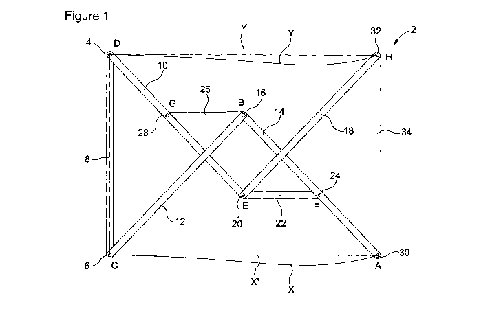
Turning to Figure 1, there is shown a diagrammatical representation of
an assembly of one embodiment of the present invention, generally indicated
as 2. The assembly 2 is shown in an extended position. The assembly 2 is
shown mounted to a fixed structure at a first fixed pivot 4 and a second fixed
pivot 6. The fixed pivots 4, 6 are spaced apart and are fixed in relation to
one
another. The fixed pivots 4, 6 are shown in Figure 1 rigidly attached to each
other by a support arm 8. However, any other rigid member or component
may be used to connect the fixed pivots 4, 6.
A first arm 10 is pivotally connected at a first position D at one end to
the first fixed pivot 4. A second arm 12 is pivotally connected at a first
position
CA 02923120 2016-03-03
WO 2015/033111
PCT/GB2014/052609
Cat one end to the second fixed pivot 6. A third arm 14 is mounted at one
end by a pivot connection 16 at the second end of the second arm 12, the
position of this connection being indicated as B in Figure 1. A fourth arm 18
is
mounted at one end by a pivot connection 20 at the second end of the first
arm 10, the position of this connection being indicated as E in Figure 1.
A first connecting arm 22 is mounted at one end by the pivot
connection 20 at the second end of the first arm 10. The second end of the
first connecting arm 22 is mounted by a pivot connection 24 to the third arm
at
a position F spaced from the position B on the third arm.
A second connecting arm 26 is mounted at one end by a pivot
connection 28 to the first arm 10 at a position G spaced from both positions D
and E. The second end of the second connecting arm 26 is mounted by the
pivot connection 16 to both the second arm 12 and the third arm 14 at position
B.
The pivot connections may be formed by any suitable means, for
example by pins extending through holes in the arms being pivotally joined.
In use, the third arm 14 and the fourth arm 18 are pivotably connected
to an object to be moved. In particular, the third arm 14 is connected to the
object by a pivot connection 30 in the distal end of the arm at a position A.
Similarly, the fourth arm 18 is connected to the object by a pivot connection
32
in the distal end of the arm at a position G. The third and fourth arms may be
connected to any object or component to be moved relative to the fixed pivots
4, 6. The component to be moved is shown in Figure 1 as a support arm 34,
by way of example.
Movement of the first arm 10 about the first fixed pivot 4 and the
second arm 12 about the second fixed pivot 6 causes the third arm 14 to
31
CA 02923120 2016-03-03
WO 2015/033111
PCT/GB2014/052609
move such that the point A on the third arm moves between a retracted
position and an extended position. In moving between the retracted position
and the extended position, the point A on the third arm 14 describes a
substantially straight line. The line of motion is indicated by the solid line
X in
Figure 1, with the corresponding straight line indicated by the broken line
X'.
Similarly, movement of the first arm 10 about the first fixed pivot 4 and the
second arm 12 about the second fixed pivot 6 causes the fourth arm 18 to
move such that the point G on the fourth arm moves between a retracted
position and an extended position. In moving between the retracted position
and the extended position, the point G on the fourth arm 18 describes a
substantially straight line. The line of motion is indicated by the solid line
Y in
Figure 1, with the corresponding straight line indicated by the broken line
Y'.
The support arm 34 is moved in a substantially straight line relative to
the fixed pivots 4, 6. The support arm is held parallel to the line joining
the
fixed pivots 4, 6 throughout its motion, in the arrangement shown in Figures 1
and 2.
An exemplary arrangement of the assembly of Figure 1 has the
dimensions set out in Table 1.
32
CA 02923120 2016-03-03
WO 2015/033111
PCT/GB2014/052609
Table 1
Dimension of assembly of Figure 1 Length (mm)
C ¨ D 1300
D ¨ E 1250
C ¨ B 1250
B ¨ A 1250
E ¨ H 1250
D ¨ G 540
G - B 500
E ¨ F 500
B ¨ F 710
G ¨ H 1085
X ¨ Y 2750
The arrangement of Table 1 provides movement of point A on the third
arm 14 and point H on the fourth arm 18 to follow approximate straight lines
X,
Y perpendicular to the line joining the fixed pivots at points C and D, the
straight line having a length of 1720 mm.
Referring to Figure 2, the assembly of Figure 1 is shown in a
perspective view in an extended condition. As can be seen, each of the first,
second, third and fourth arms 10, 12, 14, 18 is formed from two parallel,
equal
length arm members 10a, 10b, 12a, 12b, 14a, 14b, 18a, 18b. As shown, the
arm members 10a, 10b of the first arm 10 are arranged either side of the first
and second coupling arms 22, 26. The arm members of the second, third and
fourth arms are similarly arranged. In this way, the arms are able to be
folded
in the retracted position in a very compact arrangement.
33
CA 02923120 2016-03-03
WO 2015/033111
PCT/GB2014/052609
Turning now to Figures 3 to 6, there is shown a sequence of drawings
of the assembly of Figure 1 in positions between a retracted position, shown
in Figure 3, and a partially extended position shown in Figure 6.
Referring to Figure 3, the assembly 2 is shown in a retracted position.
The arms of the assembly are formed to lie within one another when in the
retracted position of Figure 3. In this way, the assembly 2 occupies the
minimum amount of space when in the retracted position.
The assembly 2 is shown in Figure 4 in a first partially extended
position, with the third and fourth arms 14, 18 having moved away from the
fixed pivots 4, 6 in the direction indicated by arrow R. In the movement from
the position of Figure 3 to the position of Figure 4, the point A at the end
of the
third arm 14 and the point H at the end of the fourth arm are following a
substantially straight line.
Figure 5 shows the assembly 2 in a second partially extended position,
with the third and fourth arms 14, 18 moved further away from the fixed pivots
4, 6. Again, points A and H on the third and fourth arms 14, 18 are tracing a
substantially straight line from their position in the retracted position of
Figure
3.
Similarly, Figure 6 shows the assembly 2 in a third partially extended
position, with the third and fourth arms 14, 18 still further from the fixed
pivots
4, 6 and the points A and H each still following a straight line path.
Further movement of the assembly from the position shown in Figure 7
brings the assembly to the extended position shown in Figures 1 and 2.
34
CA 02923120 2016-03-03
WO 2015/033111
PCT/GB2014/052609
Referring now to Figure 7, there is shown a pair of conjoined
assemblies of the general arrangement of the assembly of Figures 1 and 2.
The assemblies, generally indicated as 102a and 102b, have the general
configuration of the assembly shown in Figure 1 and components of the
assemblies are indicated using the reference numerals used in Figure 1. The
assemblies 102a, 102b are arranged in a parallel orientation and mounted to
opposing sides of a generally rectangular, vertical panel 104. In particular,
the
first and second arms 10, 12 of each assembly 102a, 102b are pivotally
connected to respective vertical sides of the panel 104.
The assemblies 102a, 102b are further connected to and support a
second panel 106. The second panel 106 is movable with respect to the
panel 104. The third and fourth arms 14, 18 of each assembly 102a, 102b are
pivotally connected to respective vertical sides of the second panel 106.
It will be understood that the panels 104, 106 are examples only of
components that may be interconnected and moved by way of the assemblies
102a, 102b. It is to be further understood that additional assemblies may be
provided, as required to move and support one component with respect to the
other.
As noted above, it has been found that the assembly of the present
invention may be combined with one or more further assemblies to provide a
straight line motion, without deviation. In particular, the assembly of the
present invention can be combined in an end-to-end configuration either with
one or more further assemblies of the present invention and/or with an
assembly as described and shown in GB1209982.6.
Turning to Figure 8, there is shown a side view of a moveable structure
comprising a first assembly 202 and a second assembly 204. The first
assembly 202 has the generally configuration of the assembly of Figure 1 and
CA 02923120 2016-03-03
WO 2015/033111
PCT/GB2014/052609
the components of the assembly are labelled using the same reference
numerals. The first assembly 202 is mounted to a support arm 8 providing the
fixed location of the fixed pivots 4, 6, the components of the first and
second
assemblies moving relative to the support arm 8 and the fixed pivots 4, 6.
The second assembly 204 is an assembly of GB1209982.6. The
second assembly 204 has the following configuration:
A first arm 210 is pivotally connected at one end to the pivoted
connection 30 of the first assembly, forming the first fixed pivot for the
second
assembly 204. A second arm 212 is pivotally connected at one end to the
pivoted connection 32, forming the second fixed pivot for the second
assembly 204. It will be noted that the first and second fixed pivots for the
second assembly 204 are inverted with respect to the first and second fixed
pivots 4, 6 of the first assembly 202.
A third arm 214 is mounted at one end by a pivot connection 216 at the
second end of the second arm 212.
A first connecting arm 222 is mounted at one end by the pivot
connection 220 at the second end of the first arm 210. The second end of the
first connecting arm 222 is mounted by a pivot connection 224 to the third arm
214, at a position on the third arm spaced from the pivot connection 216.
A second connecting arm 226 is mounted at one end by a pivot
connection 228 to the first arm 210 at a position spaced from both the pivot
30
and the pivot 220. The second end of the second connecting arm 226 is
mounted by the pivot connection 216 to both the second arm 212 and the
third arm 214.
36
CA 02923120 2016-03-03
WO 2015/033111
PCT/GB2014/052609
The pivot connections may be formed by any suitable means, for
example by pins extending through holes in the arms being pivotally joined.
Movement of the first arm 210 about the pivot 30 and the second arm
212 about the pivot 32 causes the third arm 214 to move such that the point A'
on the third arm moves between a retracted position and an extended
position. With both assemblies 202, 204 moving between the retracted
position and the extended position, the point A' on the third arm 214
describes
a straight line with no deviation therefrom, indicated by the line Z.
The structure shown in Figure 8 further comprises bracing arms 240a,
240b pivotally connected at a first end to the fourth arm 18 of the first
assembly 202 and the second arm 212 of the second assembly 204,
respectively. The bracing arms 240a, 240b are joined by a pivot connection
242 at their second ends. The pivot connection 242 is slidable along an
elongate slot 244 in the support arm 34. A force to drive the entire structure
between its retracted and extended positions may be applied to the pivot
connection 242.
Figure 9 shows a structure comprising a first assembly 302 and a
second assembly 304. Both assemblies 302, 304 are of the arrangement
shown in Figures 1 and 2 and described above. The assemblies 302, 304 are
connected in an end-to-end relationship analogous to that of the assemblies
of Figure 8, with a similar arrangement of bracing arms. Thus, the pivot
connection 30 provides the first fixed pivot for the second assembly 304 and
the pivot connection 32 provides the second fixed pivot for the second
assembly 304. The second assembly 304 is inverted with respect to the first
assembly 302.
37
CA 02923120 2016-03-03
WO 2015/033111
PCT/GB2014/052609
The third and fourth arms 14, 18 of the second assembly 304 are
connected at their distal ends to a component to be moved. In the structure of
Figure 9, the component is a support arm 310. It is to be understood that
other components may be connected to the third and fourth arms, as required.
The points A" and H" on the third and fourth arms 14, 18 respectively of
the second assembly 304 move in a precise straight line with respect to the
fixed pivots 4, 6, more particularly perpendicular to the line joining the
fixed
pivots 4, 6.
The structure of Figure 9 as shown consists of two assemblies 302,
304 interconnected. It will be understood that the structure may comprise one
or more further assemblies connected in an analogous end-to-end relationship
to that shown in Figures 8 and 9. When the total number of assemblies is an
even number, the distal or endmost moveable arms will have a point thereon
that follows a precise straight line relative to the fixed pivots 4, 6, in
particular
a line extending perpendicular to the line joining the fixed pivots.
The structure of Figure 9 is shown in a perspective view in its extended
position in Figure 10.
Figure 11 shows the structure of Figures 9 and 10 in a retracted
position. The movement of the structure from the retracted position of Figure
11 to the extended position of Figures 9 and 10 is shown in Figures 12 and
13.
In the arrangement shown, drive is applied to the structure at the pivot
connection 242 of the bracing arms 240a, 240b, for example by way of a jack
or other linear drive means. Drive may be applied to other components of the
structure, for example rotational drive applied to one or both of the first
and
second arms 10, 12. The direction of the force applied to move the structure
38
CA 02923120 2016-03-03
WO 2015/033111
PCT/GB2014/052609
from the retracted to the extended position is indicated by the arrows K.
Force applied in the reverse direction retracts the structure from the
extended
position.
Turning to Figures 14 to 17, there is shown a bridge assembly
comprising a plurality of assemblies of the present invention. The bridge
assembly, generally indicated as 402, is shown mounted on fixed structure
404 by means of a fixed vertical support member 406. The bridge assembly
402 comprises a first assembly 410 and a second assembly 412, both of the
form shown in Figure 1 and described above. The first assembly 410 has its
first and second arms connected to fixed pivots mounted on the fixed vertical
support member 406. A first moveable vertical support member 420 is
connected to the third and fourth arms of the first assembly 410. The second
assembly 412 has its first and second arms connected to pivots mounted to
the first moveable vertical support member 420. A second moveable vertical
support member 422 is connected to the third and fourth arms of the second
assembly 412. As shown in Figures 14 and 15, the second assembly 412 is
inverted with respect to the first assembly 410.
The bridge assembly 402 further comprises an assembly of
GB1209982.6, indicated as 424, having its first and second arms pivotally
connected to the second moveable vertical support member 422.
A plurality of decking members 430 are hingedly connected together
and pivotally connected to the vertical support members 406, 420, 422. A
decking member 430 is connected to each of the third arm of the first
assembly 410, the fourth arm of the second assembly 412 and the third arm of
the assembly of GB1209982.6 424, as shown in Figures 14 and 15. A further
decking member 430 is pivotally connected to the third arm of the assembly of
GB1209982.6 424.
39
CA 02923120 2016-03-03
WO 2015/033111
PCT/GB2014/052609
The bridge assembly 402 is shown in the extended position in a
perspective view in Figure 17. As can be seen, the assemblies 410, 412, 424
are arranged in pairs on either side of the vertical support members 406, 420,
422 and the decking members 430.
Turning now to Figures 18 to 20, there is shown an expandable roof
assembly comprising a plurality of assemblies of the present invention. The
roof assembly, generally indicated as 502, is mounted at an opening in a wall
of a building 504 by means of a fixed vertical support member 506. The roof
assembly is arranged in an analogous manner to the bridge assembly of
Figures 14 to 17. Thus, the roof assembly 502 comprises a first assembly
510 and a second assembly 512, both of the form shown in Figure 1 and
described above. The first assembly 510 has its first and second arms
connected to fixed pivots mounted on the fixed vertical support member 506.
A first moveable vertical support member 520 is connected to the third and
fourth arms of the first assembly 510. The second assembly 512 has its first
and second arms connected to pivots mounted to the first moveable vertical
support member 520. A second moveable vertical support member 522 is
connected to the third and fourth arms of the second assembly 512. As
shown in Figures 18 and 19, the second assembly 512 is inverted with respect
to the first assembly 510.
The roof assembly 502 further comprises an assembly of
GB1209982.6, indicated as 524, having its first and second arms pivotally
connected to the second moveable vertical support member 522.
Wheels 526 are provided on the lower end of the second support
member 522, for contacting and moving along the ground.
A plurality of roof members 530 are hingedly connected together and
pivotally connected to the vertical support members 506, 520, 522. A roof
CA 02923120 2016-03-03
WO 2015/033111
PCT/GB2014/052609
member 530 is connected to each of the fourth arm of the first assembly 510,
the third arm of the second assembly 512 and the third arm of the assembly of
GB1209982.6 424, as shown in Figures 18 and 19. A further roof member
530 is pivotally connected to the third arm of the assembly of GB1209982.6
524.
The roof assembly 502 is shown in the extended position in a
perspective view in Figure 20. As can be seen, the assemblies 510, 512, 524
are arranged in pairs on either side of the vertical support members 506, 520,
522 and the roof members 530.
Referring now to Figures 21 to 23, there is shown an expandable
gantry assembly comprising a plurality of assemblies of the present invention.
The gantry assembly, generally indicated as 602, is mounted at an opening in
a wall of a building 604 by means of a fixed vertical support member 606. The
gantry assembly is arranged in an analogous manner to the bridge assembly
of Figures 14 to 17. Thus, the gantry assembly 602 comprises a first
assembly 610 and a second assembly 612, both of the form shown in Figure 1
and described above. The first assembly 610 has its first and second arms
connected to fixed pivots mounted on the fixed vertical support member 606.
A first moveable vertical support member 620 is connected to the third and
fourth arms of the first assembly 610. The second assembly 612 has its first
and second arms connected to pivots mounted to the first moveable vertical
support member 620. A second moveable vertical support member 622 is
connected to the third and fourth arms of the second assembly 612. As
shown in Figures 21 and 22, the second assembly 612 is inverted with respect
to the first assembly 610.
A plurality of gantry members 630 are hingedly connected together and
pivotally connected to the vertical support members 606, 620, 622. A gantry
41
CA 02923120 2016-03-03
WO 2015/033111
PCT/GB2014/052609
member 630 is connected to each of the fourth arm of the first assembly 610,
the third arm of the second assembly 612, as shown in Figures 18 and 19.
A platform 632 having a railing 634 is mounted to the second vertical
support member 622, with the platform 632 in line with the gantry members
630, when in the extended position shown in Figure 22 and 23.
The gantry assembly 602 is shown in the extended position in a
perspective view in Figure 23. As can be seen, the assemblies 610, 612, 624
are arranged in pairs on either side of the vertical support members 606, 620,
622 and the gantry members 630.
42