Note: Descriptions are shown in the official language in which they were submitted.
CA 02923887 2016-03-15
PROXIMITY SENSOR
BACKGROUND
[0001] Proximity sensing devices are devices that produce an output based
upon a
distance between two or more sensors or objects. Proximity sensors typically
contain electrical
circuits having an electrical, mechanical, or optical distance sensing
portion. Electromechanical
sensors are often used to establish contact between two objects, such as an
end switch, and
electrical sensors are frequently used when a distance measurement is desired.
Electrical
proximity sensors commonly include inductance sensors, which rely on unique
electrical
properties of inductance circuits to detect the proximity of a target object.
100021 Proximity sensors are prevalent in several industries, such as
process
management, automotive, and aviation. Their applications span a large range
from traffic control
to linkage actuation control. For example, proximity sensing devices are an
integral and
indispensable component of a modern aircraft. Knowledge that a moving surface
has reached a
particular location in its travel can promote proper and safe operation of
various aircraft systems.
SUMMARY
[0003] In one embodiment, a proximity sensor includes an active sensor, a
passive target,
and a measurement circuit. The active sensor includes an active resonant tank
circuit that
includes an excitation source, a first capacitor, and a first inductor. The
passive target includes a
passive resonant tank circuit that includes a second capacitor and a second
inductor, where
magnetic coupling between the first inductor and the second inductor varies as
a function of
physical displacement of the first inductor and the second inductor with
respect to one another.
The measurement circuit is configured to measure a coupled resonant frequency
response in the
active resonant tank circuit and provide a measured distance output based on
the coupled
resonant frequency response.
[0004] In another embodiment, a proximity sensor system includes a
proximity sensor
and a controller. The proximity sensor includes an active sensor, a passive
target, and a
measurement circuit. The active sensor includes an active resonant tank
circuit that includes an
excitation source, a first capacitor, and a first inductor. The passive target
includes a passive
CA 02923887 2016-03-15
resonant tank circuit that includes a second capacitor and a second inductor,
where magnetic
coupling between the first inductor and the second inductor varies as a
function of physical
displacement of the first inductor and the second inductor with respect to one
another. The
measurement circuit is configured to measure a coupled resonant frequency
response in the
active resonant tank circuit and provide a measured distance output based on
the coupled
resonant frequency response. The controller is connected to the measurement
circuit for
controlling a system component based on the measured distance output.
[0005] In another embodiment, a method of sensing proximity includes
powering an
active sensor, measuring a coupled resonant frequency response, and producing
a measured
distance output based on the electrical response. The active sensor is
powered, which includes an
active resonant tank circuit, and is magnetically coupled to a passive
resonant tank circuit of a
passive target. The magnetic coupling between the active resonant tank circuit
and the passive
resonant tank circuit varies as a function of physical displacement between
the active and passive
resonant tank circuits with respect to one another. A coupled resonant
frequency response is
measured in the active circuit that is a function of the magnetic coupling
between the active
resonant tank circuit and the passive resonant tank circuit. A measured
distance output is
produced based on the coupled resonant frequency response.
BRIEF DESCRIPTION OF THE DRAWINGS
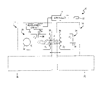
[0006] FIG. 1 is a schematic view of a proximity sensor system.
[0007] FIG. 2 is a graph illustrating frequency response versus magnetic
coupling of a
coupled resonator of the proximity sensor system of FIG. 1.
[0008] FIGS. 3A-3D are graphs illustrating time domain response versus
magnetic
coupling of a coupled resonator of the proximity sensor system of FIG. 1.
[0009] FIG. 4 is a schematic view of another embodiment of a proximity
sensor system.
DETAILED DESCRIPTION
[0010] FIG. 1 is a schematic view of proximity sensor system 10, which
includes active
sensor 12, passive target 14, controller 16, first structure 18, second
structure 20, and system
components 22. Active sensor 12 includes measurement circuit 24 and active
resonant tank
circuit 26. Active resonant tank circuit 26 includes capacitor 28, inductor
30, and excitation
2
CA 02923887 2016-03-15
source 32. Passive target 14 includes passive resonant tank circuit 34, which
includes inductor 36
and capacitor 38. Also shown in FIG. 1 are distance d, capacitance C1,
capacitance C21
inductance LI, Inductance L2, drive signal voltage Võ sensor output voltage
Vo, and magnetic
field B.
[0011] Active sensor 12 is physically connected to first structure 18 by
welding, riveting,
screwing, co-molding, or another fastening means. Also, active sensor 12 can
be enclosed by a
housing (not shown) which can then be attached to first structure 18.
Similarly, passive target 14
is physically connected to second structure 20 by welding, riveting, screwing,
co-molding, or
another fastening means. Also, passive target 14 can be enclosed by a housing
(not shown)
which can then be attached to second structure 20. Active sensor 12 and
passive target 14 are
fixed to first structure 18 and second structure 20, respectively. However,
active sensor 12 and
passive target 14 can move relative to one another, as first structure 18 and
second structure 20
can move with respect to each other. Distance d represents the physical
distance between
inductor 30 and inductor 36. Because inductor 30 is a component of active
sensor 12, which is
attached to first structure 18, distance d between inductors 30 and 36 can be
easily correlated to
other distances, such as a distance between active sensor 12 and passive
target 14, and their
respective components. In one example, first structure 18 and second structure
20 can be
connected to each other but still free to move relative to each other, for
example as parts of a
linkage assembly.
[0012] Measurement circuit 24 can be physically attached to first
structure 18 by
welding, riveting, screwing, co-molding, or another fastening means.
Additionally, measurement
24 can be on a common printed circuit board with active sensor 12 or can
otherwise be integrated
into active sensor 12. For example, measurement circuit 24 and active resonant
tank circuit 26
can be within a common housing within active sensor 12. Controller 16 can be
mounted to first
structure 18 or second structure 20; however, in many examples controller 16
can be mounted
physically remotely from first structure 18 and second structure 20.
[0013] Capacitor 28 of active resonant tank circuit 26 is electrically
connected in series
with inductor 30 and excitation source 32. Capacitor 28 has a capacitance CI,
and inductor 30
has an inductance LI. Excitation source 32 produces a drive signal voltage Vs.
[0014] Capacitor 38 of passive resonant tank circuit 34 is connected with
inductor 36 in
parallel. Capacitor 38 has a capacitance C2, and inductor 36 has an inductance
L2. Capacitors 28
3
CA 02923887 2016-03-15
and 38 can be a ceramic capacitor, film capacitor, or any type of capacitor
capable of storing
electrical energy and having sufficient quality factor Q to operate
effectively in a resonant
circuit. Inductors 30 and 36 can be a ferromagnetic inductor, an air core
inductor, or any other
type of inductor having sufficient quality factor Q to operate effectively in
a resonant circuit.
Excitation source 32 can be an alternating current (AC) power supply for
producing a current or
excitation pulse.
[0015] Active resonant tank circuit 26 and its components create an
active series
resonator circuit, also known as a tank circuit, resonant circuit, or tuned
circuit. Passive resonant
tank circuit 34 and its components create a passive parallel resonator
circuit, also known as a
tank circuit, resonant circuit, or tuned circuit.
[0016] Measurement circuit 24 is connected to active resonant tank
circuit 26 across
capacitor 28. Measurement circuit 24 measures sensor output voltage Vo.
Measurement circuit 24
is also electrically connected to controller 16, which further electrically
connects to system
components 22. System components 22 can be any system component capable of
being moved
or articulated. For example, first structure 18 and second structure 20 could
be system
components 22.
[0017] In operation of one embodiment, excitation source 32 sends a
current to capacitor
28, which stores charge and ultimately discharges the current to inductor 30.
Inductor 30, in
response, creates magnetic field B, which oscillates in response to the
alternating current.
Excitation source 32 provides continuous power to active resonant tank circuit
26 creating
continuous oscillations of magnetic field B at the natural frequency of active
resonant tank circuit
26, creating resonance.
[0018] Passive resonant tank circuit 34 is tuned to the same or similar
resonant frequency
of active circuit 32, where the product of capacitor 28 and inductor 30 can be
approximately
equal to the product of capacitor 38 and inductor 36. When passive resonant
tank circuit 34 is
within range of magnetic field B, passive resonant tank circuit 34 and active
resonant tank circuit
26 become magnetically coupled. When coupled, magnetic field B will induce a
current through
inductor 36, which will flow in passive resonant tank circuit 34. In response
to this current flow,
Lenz's law dictates that inductor 36 will produce a magnetic field in a
direction opposite of that
created by inductor 30. The magnetic field response by inductor 36 is received
by inductor 30 of
4
CA 02923887 2016-03-15
active resonant tank circuit 26. The reflected load can create a coupled
resonant frequency
response fe. 1, or an electrical response, in active resonant tank circuit 26.
[0019] The electrical response in active resonant tank circuit 26 is
detectible by
measuring and analyzing the current through or the voltage across a component
of active
resonant tank circuit 26. In one example, measurement circuit 24 measures the
voltage across
capacitor 28 to observe coupled resonant frequency responses fa and fa through
active resonant
tank circuit 26. In other embodiments, measurement circuit 24 can measure the
voltage across
any component of active resonant tank circuit 26. Measurement circuit 24 can
include an
oscillator, demodulator, and other components to obtain an accurate
measurement of coupled
resonant frequency responses/ and fa.
[0020] In designs of active resonant tank circuit 26 and passive resonant
tank circuit 34, a
unique, easily detectible response can be observed through a measurement of
coupled resonant
frequency response ti; however, for the response to be unique, easily
detectible, and useful as a
proximity sensor, some conditions can be met. The first condition is that a
circuit quality factor
Q is greater than 1 for both circuits, or:
[0021] Q'> 1 and Q2> 1
(Eq. 1A)
[0022] Where Q] is the quality factor of active resonant tank circuit 26
and Q2 is the
quality factor of passive resonant tank circuit 34. However, it is preferred
that quality factors Q/
and Q2 are much greater than one (in many embodiments, at least one order of
magnitude, i.e. ten
times greater), or:
[0023] Q'>> 1 and Q2 >> 1
(Eq. 1B)
[0024] The quality factor of active resonant tank circuit 26 is given by
the equation
Irt
[0025] Qi 1¨
(Eq. 2A)
[0026] Where R1 is the resistance of active resonant tank circuit 26. The
quality factor of
passive resonant tank circuit 34 is given by the equation
[0027]RQ,
(Eq. 2B)
[0028] Where R2 is the resistance of passive resonant tank circuit 34. In
some
embodiments, R1 and R2 can be only the parasitic resistance of their
respective circuit, because
the circuit contains no added resistor component, as it is desired to maintain
a high quality factor
in each circuit.
CA 02923887 2016-03-15
[00291 A
second condition that can be met is that resonant frequencies or both
circuitsfizi
and offR2 can be approximately equal. The resonant frequency for each circuit
is determined by
the equations:
[0030] = _________________________________________________________
(Eq. 3A)
L,=C,
[0031] = _________________________________________________________
(Eq. 3B)
[0032] Because the resonant frequency for each circuit is dependent
primarily on that
circuits' inductance and capacitance, especially in some embodiments, when
quality factors Qi
and Q2 are much greater than one, the product of the inductance and
capacitance of each circuit
must be approximately equal to that of the other circuit, or:
[0033] * L2 * C2
(Eq. 4)
[0034]
The third condition that can be met is that a coefficient of coupling k
between
active resonant tank circuit 26 and passive resonant tank circuit 34 can be
greater than a critical
coefficient of coupling k, between active resonant tank circuit 26 and passive
resonant tank
circuit 34. The coefficient of coupling k is the magnetic coupling coefficient
between circuits,
which ranges from zero to one, or 0 < k < 1, and is defined by
[0035] k (Eq. 5)
[0036]
Where M is the mutual inductance of inductors L1 and L2 or inductors 30 and
36.
The mutual inductance M of inductors 30 and 36 correlates directly and varies
with distance d.
[0037]
The critical coefficient of coupling k, between active resonant tank circuit
26 and
passive resonant tank circuit 34 is given as
[0038] k
(Eq. 6)
õQi-Q2
[0039] Therefore, the third condition can become
[0040]
(Eq. 7)
[0041]
In an exemplary embodiment, the coupled resonant frequency responses fa and
fc2
of active resonant tank circuit 26 and the passive resonant tank circuit 34
can be determined by
the equations
[0042] f =fR1
(Eq. 8A)
[0043]j fR:
(Eq. 8A)
C'
6
CA 02923887 2016-03-15
[0044] Here, the coupled resonant frequency responses fc. jand fc2 of
active resonant tank
circuit 26 and passive resonant tank circuit 34, respectively, are dependent
only on the uncoupled
resonant frequencies JR/ and fR2, respectively, and the coefficient of
coupling k between active
resonant tank circuit 26 and passive resonant tank circuit 34. Because the
uncoupled resonant
frequency will be fixed by the inductance L and capacitance C of each circuit,
the coupled
resonant frequency responses.fej and 1fc2 are primarily dependent on the
coefficient of coupling k.
For example, the coupled resonant frequency response fi of active resonant
tank circuit 26 is
primarily dependent on the coefficient of coupling k between active resonant
tank circuit 26 and
passive resonant tank circuit 34. The coefficient of coupling k between active
resonant tank
circuit 26 and passive resonant tank circuit 34 is given by Equation 5 above,
where M is the
mutual inductance of inductors L1 and L2 or inductors 30 and 36. The mutual
inductance M of
inductors 30 and 36 is primarily dependent on distance d, the distance between
inductors 30 and
36. This means the coefficient of coupling k is primarily dependent on
distance d, and that the
coupled resonant frequency responses fa and 1c2 are then primarily dependent
on distance d.
Therefore, with active resonant tank circuit 26 and passive resonant tank
circuit 34 meeting the
exemplary conditions, the electrical response, or the coupled resonant
frequency response /, in
active resonant tank circuit 26 caused by an interaction with passive resonant
tank circuit 34
becomes a function primarily dependent on distance d between inductors 30 and
36.
[0045] Thus, the coupled resonant frequency response fd, or electrical
response, can be
measured by measurement circuit 24 and transformed into a measured distance
output to be used
by, for example, controller 16. Essentially, active resonant tank circuit 26
and passive resonant
tank circuit 34 to be used to sense proximity or distance. Further, with
sufficient physical
information regarding active sensor 12 and its components and passive target
14 and its
components, the electrical response can be correlated to the separation in
distance d between
active sensor 12 and passive target 14.
[0046] Distance d represents the physical distance between inductor 30
and inductor 36.
Because inductor is a component of active sensor 12 and inductor 36 is a
component of first
structure 18, distance d between inductors 30 and 36 can be easily correlated
to other distances
between active sensor 12 and first structure 18, and their respective
components.
100471 The prior art includes proximity sensors that can include an
active tank circuit of
an active sensor and a ferromagnetic passive target. While a ferromagnetic
target does produce
7
CA 02923887 2016-03-15
an electrical response in the active circuit by affecting the magnetic field
of the tank circuit's
inductor, the application has some drawbacks. First, these sensors can have a
small physical
operating range, or struggle to operate over a large distance d. This imposes
tight calibration
requirements to allow the desired signal to be detected by the active sensor.
Therefore, the
electronic signature produced by this type of system can, in some examples,
vary by only a few
percent between a near condition (when the target is very close to the active
sensor) and the far
condition (when the target is relatively distant from the active sensor).
Further, because the
active sensor is designed to interact with ferromagnetic passive targets
impacting the magnetic
field of the active circuit, the circuit is susceptible to ambient noise and
interference. To account
for such interference, can require a complicated design of the signal
conditioning and
measurement electronics interacting with the active portion of the sensor.
This can increase the
cost and complexity of the devices.
[0048] This disclosure addresses these issues by using specifically
designed coupled
resonators, which produce a unique electrical response, as described in more
detail below, when
active resonant tank circuit 26 and passive resonant tank circuit 34 are
magnetically coupled.
Because the electrical response in active resonant tank circuit 26 is a
coupled resonant frequency
response lci it is a function of distance d between inductors 30 and 36, and
it is more easily
detected and determined by measurement circuit 24. This is particularly
helpful at large distances
between active resonant tank circuit 26 and passive resonant tank circuit 34,
when noise is more
likely to impact the detected signal, because noise may not disturb the change
in coupled
frequency responses ,f,] and f2. This permits detection to occur at greater
distances. This also
permits finer resolution of the detection of distance d, which leads to a
higher measurement
accuracy. This is all accomplished while maintaining the simplicity of using a
passive target
circuit, which provides the benefit of being robust.
[0049] FIG. 2 is a graph illustrating one embodiment of frequency
response versus the
coefficient of coupling k of active resonant tank circuit 26 and passive
resonant tank circuit 34
FIG. 1. Frequency f is displayed on the x-axis of the graph and magnitude Mag
is displayed on
the y-axis of the graph. Also displayed on the graph are four response curves,
curve 40, curve 42,
curve 44, and curve 46.
[0050] Magnitude Mag has a range on the y-axis of 0 decibels (dB) to
magnitude Mag of
140 dB, with intermediate markers along the y-axis denoting steps of 20 dB.
Frequency [moves
8
CA 02923887 2016-03-15
from the left to the right side of its axis, ranging from 4.4 x 10⁵ Hertz (Hz)
to 5.8 x 10⁵ Hz at its
maximum, with increments of 0.2 x 10⁵ Hz denoted.
[0051] The graph legend displays the corresponding values of coefficient
of coupling k to
curves 40, 42, 44, and 46. Specifically, curve 40 is a response curve where
the coefficient of
coupling k between active resonant tank circuit 26 and passive resonant tank
circuit 34 is 0.001,
curve 42 is a response curve where the coefficient of coupling k between
active resonant tank
circuit 26 and passive resonant tank circuit 34 is 0.01, curve 44 is a
response curve where the
coefficient between coupling k of active resonant tank circuit 26 and passive
resonant tank circuit
34 is 0.1, and curve 46 is a response curve where the coefficient of coupling
k between active
resonant tank circuit 26 and passive resonant tank circuit 34 is 0.2.
Detecting or observing these
responses in active resonant tank circuit 26 can be performed using any
standard technique.
[0052] Curves 40, 42, 44, and 46 represent the signature of the
electrical response signal
in active resonant tank circuit 26 based on the coefficient of coupling k,
showing how much of
the signal is within each frequency. Curve 40, which represents a coefficient
of coupling k of
0.001, has a single discernable resonant frequency signature having a single
peak amplitude in
the displayed range. Curve 40 displays a frequency response having a
coefficient of coupling k of
0.001, which is so low that the coupled frequency responses .fa and fa are
nearly equal to
resonant frequencyfRi of active resonant tank circuit 26. This is given by the
equation:
[0053] fc/ f2121
(Eq. 9)
[0054] Curve 42, which represents a coefficient of coupling k of 0.01,
depicts a curve
showing a split frequency response. Curve 42 has a signature having coupled
frequency
responsesfa and fa separated by 0.05 x 10⁵ Hz as curve 42 has a split peak
amplitude (or double
hump curve), having a trough at the same frequency of the peak of curve 40.
The coupled
frequency response fa of curve 42 occurs at approximately 5.0 x 10⁵ 1 lz and
coupled frequency
response fc2 occurs at approximately 5.05 x 10⁵ Hz.
[0055] Curve 44, which represents a coefficient of coupling k of 0.1, has
a signature with
coupled frequency responses fa and J2 at approximately 4.8 x 10⁵ Hz and 5.3 x
105 Hz. The
separation in peaks of curve 44 is 0.5 x 10⁵ Hz, which is significantly
greater than the separation
between peaks in curve 42, which is approximately 0.05 x 10⁵ Hz. This resonant
frequency
response separation effect is even greater in curve 46, which has peaks at
approximately 4.6 x
105 Hz and 5.65 x 10⁵ Hz. Also, the magnitudes of the peaks in curve 46
differ. The magnitude
9
CA 02923887 2016-03-15
of the 4.6 x 10⁵ Hz peak is approximately 70 dB, while the magnitude of the
5.65 x 10⁵ Hz peak
is approximately 58 dB, a difference of 12 dB. Curve 44 has a difference of
approximately 3 dB
in peak magnitude.
[0056] Other signatures of signals having a coefficient of coupling k
between 0.001 and
0.2, though not shown, will also vary, as will the signatures of electrical
response signals greater
than a coefficient of coupling k of 0.2. These differences in curves 40, 42,
44, and 46, as well as
those with other coefficients of coupling k, are apparent and easily
detectible, even at low
coefficients of coupling k, such as 0.01. Because the differences between
curves 40, 42, 44, and
46 are readily discernible when the components of active resonant tank circuit
26 and passive
resonant tank circuit 34 are designed in accordance with exemplary
embodiments, these response
signatures can be easily mapped to their coefficients of coupling k. Then,
when a response is
observed it can be correlated to a coefficient of coupling k, which can then
be translated into a
distance between inductors 30 and 36, allowing for proximity detection to be
easily performed.
[0057] In one embodiment, distance d between components of active
resonant tank
circuit 26 and passive resonant tank circuit 34 can be determined based on its
proportionality to
the distance, or the difference, between the coupled frequency responses fi
and.fiz. This is given
by equations:
[0058] If ¨ f2Ic
(Eq. 10A)
1
[0059] f2 f c(Eq. 10B)
[0060] In another embodiment, distance d between components of active
resonant tank
circuit 26 and passive resonant tank circuit 34 can be determined based on its
proportionality to
the difference or distance between either coupled frequency response ti and f2
and resonant
frequencyfRi of active resonant tank circuit 26, given by equations:
[0061] f R1 -f1 CK
(Eq. 11A)
[0062] f,1 f o
(Eq. (Eq. 11B)
[0063] Though specific values are shown in FIG. 2, a frequency response
can be over
many frequency ranges and many magnitude ranges.
[0064] FIGS. 3A-3D are graphs of four embodiments illustrating time
domain responses
versus the coefficient of coupling k of active resonant tank circuit 26 and
passive resonant tank
circuit 34 of FIG. 1. FIGS. 3A-3D are discussed concurrently. In FIGS. 3A-3D
time / is
CA 02923887 2016-03-15
displayed on the x-axis of each graph and magnitude Mag is displayed on the y-
axis of each
graph. Time t ranges from 0 seconds to 2.5 x 10⁻⁴ seconds at its maximum, with
increments of
0.5 x 10⁻⁴ seconds denoted. The magnitude mag spans from -20 dB to 20 dB on
the y-axis, with
intermediate markers denoting steps of 5 dB.
[0065] FIGS. 3A-3D display a time domain response of an impulse
excitation measured
in active resonant tank circuit 26. Each of FIGS. 3A-3D displays a response at
a different
coefficient of coupling k between active resonant tank circuit 26 and passive
resonant tank circuit
34. Specifically, FIG. 3A shows response curve 48 where the coefficient of
coupling k between
active resonant tank circuit 26 and passive resonant tank circuit 34 is 0.001.
FIG. 3B shows
response curve 50 where the coefficient of coupling k between active resonant
tank circuit 26
and passive resonant tank circuit 34 is 0.01. FIG. 3C shows response curve 52
where the
coefficient between coupling k of active resonant tank circuit 26 and passive
resonant tank circuit
34 is 0.1, and FIG. 3D shows response curve 54 where the coefficient between
coupling k of
active resonant tank circuit 26 and passive resonant tank circuit 34 is 0.2.
[0066] Curves 48, 50, 52, and 54 vary significantly in their signature in
many ways. The
amplitude of curve 48 begins at approximately 40 dB and slowly decays to near
0 dB over the
time domain while its frequency remains constant. The amplitude of curve 50
begins at
approximately 40 dB and decays to nearly 0 dB at 1 x 10⁻⁴ seconds before
beginning to increase
again. The amplitude of curve 52 decays quickly and then rapidly increases,
but its original
amplitude decreases in each successive cycle, decaying with time as it
oscillates. Curve 54 is
similar to curve 52, but the amplitude cycle of curve 52 occurs at a higher
frequency than that of
curve 54.
[0067] Other signatures of signals having a coefficient of coupling k
between 0.001 and
0.2, though not shown, will also vary, as will the signatures of signals
greater than a coefficient
of coupling k of 0.2. These differences in curves 48-54, as well as those with
other coefficients of
coupling k, are apparent and easily detectible, even at low coefficients of
coupling k, such as
0.01. Because the differences between curves 48-54 are readily discernible
when the components
of active resonant tank circuit 26 and passive resonant tank circuit 34 are
designed in accordance
with exemplary embodiments, these response signatures can be easily mapped to
their
coefficients of coupling k. Then, when a response is observed by analyzing its
waveform from a
pulse excitation, it can be correlated to a coefficient of coupling k, which
can then be translated
11
CA 02923887 2016-03-15
into a distance between inductors 30 and 36, allowing for proximity detection
to be easily
performed.
[0068] In one embodiment, distance d between components of active
resonant tank
circuit 26 and passive resonant tank circuit 34 can be determined using an
envelope detection
method, where the detected frequency /J.,/ is proportional to the coefficient
of coupling k and
distance d. In one embodiment, detected frequency jd'e, increases as the
coefficient of coupling k
increases.
[0069] In another embodiment, a Fourier transform can be performed on the
detected
curve, where the resultant curve, or data set, can be analyzed in the
frequency domain as
described in FIG. 2. Though specific embodiments to determine distance d are
described, other
methods of analyzing the coupled frequency responses fa and jc2 to determine
distance d can be
used.
[0070] Though specific values are shown in FIGS. 3A-3D, a frequency
response can be
over many time domain ranges and many magnitude ranges.
[0071] FIG. 4 is a schematic view of proximity sensor system 10a, which
includes active
sensor 12, passive target 14, controller 16, first structure 18, second
structure 20, system
components 22, and measurement circuit 24. Active sensor 12 includes active
resonant tank
circuit 26, which includes capacitor 28, inductor 30, excitation source 32,
and current sense
resistor 56. Passive target 14 includes passive resonant tank circuit 34,
which includes capacitor
38and inductor 36. Also shown in FIG. 1 are distance d and magnetic field B.
[0072] The components of sensor system 10a are connected consistently
with those of
sensor system 10 of FIG. 1, except for measurement circuit 24. Measurement
circuit 24 is not
physically connected to active object 18 and is not a component of active
sensor 12.
Additionally, measurement circuit 24 is electrically connected to active
resonant tank circuit 26
across current sense resistor 56, which has a resistance R. However,
measurement circuit 24 is
still electrically connected to controller 16.
[0073] The components of sensor system 10a also operate consistently with
those of
sensor system 10, except that in this embodiment, measurement circuit 24
measures the current
across current sense resistor 56. Current sense resistor 56 can be either a
fixed or variable resistor
that enables current measurement. This measurement allows for the electrical
response generated
by the magnetic coupling of active resonant tank circuit 26 and passive
resonant tank circuit 34
12
CA 02923887 2016-03-15
to be analyzed in the frequency domain and time domain. In other embodiments,
the current can
be measured at other parts of active resonant tank circuit 26.
[0074] In one embodiment, controller 16 can control system components 22,
which can
be first structure 18 or second structure 20, based on the measured distance
output from
measurement circuit 24. Current measurement can also be accomplished by
measuring the
current through other components of active sensor 12.
[0075] Discussion of Possible Embodiments
[0076] The following are non-exclusive descriptions of possible
embodiments of the
present invention.
[0077] A proximity sensor includes an active sensor, a passive target,
and a measurement
circuit. The active sensor includes an active resonant tank circuit that
includes an excitation
source, a first capacitor, and a first inductor. The passive target includes a
passive resonant tank
circuit that includes a second capacitor and a second inductor, where magnetic
coupling between
the first inductor and the second inductor varies as a function of physical
displacement of the
first inductor and the second inductor with respect to one another. The
measurement circuit is
configured to measure a coupled resonant frequency response in the active
resonant tank circuit
and provide a measured distance output based on the coupled resonant frequency
response.
[0078] The proximity sensor of the preceding paragraph can optionally
include,
additionally and/or alternatively, any one or more of the following features,
configurations
and/or additional components.
[0079] The active resonant tank circuit and the passive resonant tank
circuit can be tuned
to substantially equal resonant frequencies.
[0080] The active tank circuit can have a quality factor Q1 greater than
one and the
passive tank circuit can have a quality factor Q2 greater than one.
[0081] The active tank circuit and passive tank circuit can have a
coefficient of coupling,
and the coefficient of coupling can be at least as large as a critical
coefficient of coupling
between the active resonant tank circuit and the passive resonant tank
circuit.
[0082] The coupled resonant frequency response can be determined by
analyzing a
voltage across a component of the active resonant tank circuit.
[0083] The coupled resonant frequency response can be determined by
analyzing a
current through the active resonant tank circuit.
1:3
CA 02923887 2016-03-15
[0084] The measurement circuit can determine a distance between the
active sensor and
the passive target by analyzing the coupled resonant frequency response versus
a coefficient of
coupling.
[0085] The measurement circuit can determine a distance between the
active sensor and
the passive target by analyzing the coupled resonant frequency response in a
time domain versus
a coefficient of coupling.
[0086] A proximity sensor system includes a proximity sensor and a
controller. The
proximity sensor includes an active sensor, a passive target, and a
measurement circuit. The
active sensor includes an active resonant tank circuit that includes an
excitation source, a first
capacitor, and a first inductor. The passive target includes a passive
resonant tank circuit that
includes a second capacitor and a second inductor, where magnetic coupling
between the first
inductor and the second inductor varies as a function of physical displacement
of the first
inductor and the second inductor with respect to one another. The measurement
circuit is
configured to measure a coupled resonant frequency response in the active
resonant tank circuit
and provide a measured distance output based on the coupled resonant frequency
response. The
controller is connected to the measurement circuit for controlling a system
component based on
the measured distance output.
[0087] The system of the preceding paragraph can optionally include,
additionally and/or
alternatively, any one or more of the following features, configurations
and/or additional
components.
[0088] The active resonant tank circuit and the passive resonant tank
circuit can be tuned
to substantially equal resonant frequencies.
[0089] The active tank circuit can have a quality factor Q1 greater than
one and the
passive tank circuit can have a quality factor Q2 greater than one.
[0090] The active tank circuit and the passive tank circuit can have a
coefficient of
coupling, and the coefficient of coupling can be at least as large as a
critical coefficient of
coupling between the active resonant tank circuit and the passive resonant
tank circuit.
[0091] The measurement circuit can determine a distance between the
active sensor and
the passive target by analyzing one of the coupled resonant frequency response
versus a
coefficient of coupling or the coupled resonant frequency response in a time
domain versus a
coefficient of coupling.
14
CA 02923887 2016-03-15
[0092] A sensing object can attach the active sensor.
[0093] A target object can attach the passive target, and the target
object and the sensing
object can be movable with respect to one another.
[0094] The controller can control one of the sensing object or the target
object based on
the measured distance output.
[0095] A method of sensing proximity includes powering an active sensor,
measuring a
coupled resonant frequency response, and producing a measured distance output
based on the
electrical response. The active sensor is powered, which includes an active
resonant tank circuit,
and is magnetically coupled to a passive resonant tank circuit of a passive
target. The magnetic
coupling between the active resonant tank circuit and the passive resonant
tank circuit varies as a
function of physical displacement between the active and passive resonant tank
circuits with
respect to one another. A coupled resonant frequency response is measured in
the active circuit
that is a function of the magnetic coupling between the active resonant tank
circuit and the
passive resonant tank circuit. A measured distance output is produced based on
the coupled
resonant frequency response.
[0096] The method of the preceding paragraph can optionally include,
additionally
and/or alternatively, any one or more of the following features,
configurations and/or additional
components, or steps.
[0097] The active resonant tank circuit and the passive resonant tank
circuit can be tuned
to substantially equal resonant frequencies.
[0098] The measured distance output can be sent to a controller.
[0099] A system component can be controlled based on the measured
distance output.
[00100] While the invention has been described with reference to an
exemplary
embodiment(s), it will be understood by those skilled in the art that various
changes may be
made and equivalents may be substituted for elements thereof without departing
from the scope
of the invention. In addition, many modifications may be made to adapt a
particular situation or
material to the teachings of the invention without departing from the
essential scope thereof.
Therefore, it is intended that the invention not be limited to the particular
embodiment(s)
disclosed, but that the invention will include all embodiments falling within
the scope of the
appended claims.