Note: Descriptions are shown in the official language in which they were submitted.
CA 02923931 2016-03-16
=
DEVICE AND METHOD FOR EXHAUSTING
STEAM IN CURED-IN-PLACE PIPELINING
BACKGROUND
This application is based upon United States Provisional Application Serial
Number 62/133,792 filed March 16, 2015, the complete disclosure of which is
hereby
expressly incorporated by this reference.
The invention relates generally to a device and method for repairing a pipe or
other underground structure, such as an underground sewer pipe in
communication
with a house or building. More particularly, but not exclusively, the
invention relates to
a method of exhausting steam in steam curing a cured-in-place liner that
avoids venting
or directing steam toward the house or building.
As the infrastructure of major cities and towns in the developed world age,
the
sewer systems weaken. Pipe degradation, system blockage, water infiltration,
and
sewer leakage are major problems that aging sewer systems experience. As these
problems persist, the sewer system may eventually experience total failure and
entire
sections of the sewer system may collapse. As a result, sinkholes may form and
sewers
may back up into homes and places of business. One method of addressing this
critical
infrastructure problem is the use of pipe lining techniques to rehabilitate
existing sewer
systems.
Cured-in-place pipelining (CIPP) is one such technique that includes
rehabilitating an
existing sewer system by creating a new pipe within an existing pipe. A liner,
1
CA 02923931 2016-03-16
impregnated with a resinous material capable of curing and hardening, is
inverted or
pulled into a damaged pipe. The liner is pressed against the wall of the
existing pipe,
and the resinous material is allowed to cure and harden. The result is a
replacement
pipe having the older pipe or "host pipe" on the exterior. The cured-in-place
pipe acts to
alleviate the problems caused by structural defects and blockages in the
existing sewer
system.
The use of steam to cure CIPP liners has become commonplace. Steam is used in
conjunction with pressurized air in a bladder to keep the liner pressed
against the host
pipe and distribute the steam from one end of the liner to other. An exhaust
port is
typically provided at one end of the bladder to allow for continuous flow-
through
without deflating the bladder prior to completing the curing process. For
example,
where a lateral liner is inverted from a main pipe into a lateral pipe and
steam is used to
cure the resin in the liner, the exhaust port will be at the end of the
bladder nearest the
house or building connected to the lateral pipe. The steam normally has an
unpleasant
odor. Thus, when the exhausted steam backs up into the house or building, the
occupants are subjected to unpleasant odors.
Thus, there is a need in the art for a device and method for exhausting steam
away from the house or building in communication with the pipeline.
SUMMARY
One aspect of the invention includes a method of exhausting steam in steam
curing a cured-in-place liner that avoids directing the steam toward a house
or building
2
CA 02923931 2016-03-16
in communication with a pipeline in need of repair. The method generally
includes the
use of a liner, a bladder, and an exhaust hose operatively connected to the
bladder. A
resinous material capable of curing and hardening is applied to the liner. The
bladder
presses the liner against the pipeline. The end of the steam exhaust hose
connected to
the bladder is positioned on the interior of the bladder and the opposite end
of the
steam house is positioned outside the bladder to direct steam away from the
house or
building. Steam is introduced inside the bladder to assist in curing the
resinous
material, and the exhaust hose exhausts steam outside of the bladder and away
from
the house or building in communication with the pipeline.
Another aspect of the invention includes an apparatus for repairing a damaged
section of a pipeline. The apparatus generally includes a bladder, a liner and
an exhaust
hose. A closed end of the bladder is operatively connected to one end of the
exhaust
hose. With inversion of the liner and bladder into the pipeline, the end of
the exhaust
hose connected to the bladder is disposed within the bladder and extends
toward the
opposite end of the bladder.
Another aspect of the invention includes a method of exhausting steam in steam
curing a cured-in-place liner assembly disposed at the junction between a main
and
lateral sewer pipe. In steam curing the liner assembly, an exhaust hose
directs steam
through away from the house or building in communication therewith. In one
embodiment the steam is exhausted into the main pipe. In alternate embodiments
the
steam is exhausted into the lateral pipe or a cleanout pipe.
3
CA 02923931 2016-03-16
Yet another aspect of the invention includes an apparatus for repairing the
junction between a main sewer pipe and lateral sewer pipe that includes an
exhaust
hose to effectively exhaust steam in a steam curing process as described
above.
These and other aspects of the invention will be illustrated in exemplary
embodiments described and shown herein.
BRIEF DESCRIPTION OF THE DRAWINGS
FIG. 1 is a perspective view of an embodiment of the invention.
FIG. 2 is a section view of an embodiment of the invention positioned in a
pipe
system before inversion.
FIG. 3 is a section view of an embodiment of the invention positioned in a
pipe
system after inversion.
FIG. 4 is a perspective view of an embodiment of the invention.
FIG. 5 is a section view of an embodiment of the invention positioned in a
pipe
system before inversion.
FIG. 6 is a section view of an embodiment of the invention positioned in a
pipe
system after inversion.
DETAILED DESCRIPTION OF EXEMPLARY EMBODIMENTS
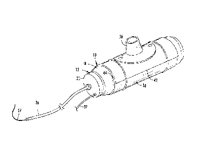
Referring to FIGS. 1-3, a repair assembly is generally designated by the
numeral
10. Repair assembly 10 includes a launcher device 12 having mounted thereto a
liner
assembly 14. In one embodiment the liner assembly 14 is an elongated tube
adapted to
4
CA 02923931 2016-03-16
line the inside of a single length of pipe. In alternate embodiments, a T-
shaped or Y-
shaped liner assembly 14 may be used to line the intersection of two pipes,
such as a
main pipe 50 and a lateral pipe 52. Repair assembly 10 also houses a bladder
assembly
16, which may be an elongated tube adapted be positioned inside the liner
assembly 14
used to line a single length of pipe. Alternatively, the bladder assembly 16
may be a T-
shaped or Y-shaped bladder assembly 16. T-shaped or Y-shaped bladder tube
assembly
16 includes a main bladder tube 34 and a lateral bladder tube 36. Similarly,
the T-
shaped or Y-shaped liner assembly 14 includes a main liner tube 38 and a
lateral liner
tube 40. The bladder assembly 16 is fitted on the interior of the liner
assembly 14. In the
particular configuration shown in FIGS. 1-3, the liner assembly 14 and bladder
assembly
16 are T-shaped, but they can also be single tubes to line a single pipe or a
Y-shaped to
accommodate a lateral pipe that intersects with a main pipe at an oblique
angle.
Launcher device 12 includes side walls 18, a first end 20 and an opposite end
wall 22. The first end 20 includes an aperture 24 through which an exhaust
hose 26
extends. A first end of the exhaust hose 26 is connected to an inversion rope
27 and a
second end of the exhaust hose 26 is connected to a closed bladder tube end 28
or
operatively connected to the bladder tube end 28 through a second inversion
rope 25, d-
ring, or other connecting means (FIG. 3). In one embodiment the exhaust hose
26 is
inserted through the aperture 24 before being connected to the closed bladder
tube end
28. Also extending through first end 20 of the launcher device 12 is an air
inlet port 30
and a back pressure port. The air inlet port 30 is connected to a source of
pressurized
air (not shown) via an air hose 32. The back pressure port and associated back
pressure
5
CA 02923931 2016-03-16
hose and pressure gauge can be used to monitor the static pressure when
pressurized
air is provided to the launcher cavity 48.
As can be seen in FIG. 1, the main liner tube 38 is comprised of what is
initially a
flat sheet of material which is wrapped around the outside of the main bladder
tube 34
and the launcher device 12. The main liner tube 38 includes overlapping edges
42, 44.
The launcher device 12 includes a launcher device opening 46, and the lateral
liner tube
40 is contained within the launcher device cavity 48 as shown in FIG. 2.
Similarly, the
lateral bladder tube 36 is contained within the launcher cavity 48 and
surrounds the
lateral liner tube 40. Both the main liner tube 38 and the lateral liner tube
40 are
comprised of a felt layer, which is the lining surface that contacts the
interior surface of
the host pipe, and a polymer coating is on the opposite surface. A resinous
material
capable of curing and hardening is applied to the felt layer of the main liner
tube 38 and
the lateral liner tube 40 using a vacuum impregnation process, as is known in
the art,
preferably prior to loading the liner assembly 14 on the launcher device 12.
As described above, the main portion of the liner assembly 14 is preferably
formed as a tube. However the main liner member can be sized so that it only
engages
a portion of the cylindrical main pipe 50.
FIGS. 2 and 3 show the repair assembly 10 within a main pipe 50 which is
connected to a lateral pipe 52. The damaged portion 54 is shown needing
repair.
Ground water from outside the lateral pipe 52 and the main pipe 50 will seep
through
the damaged portion 54 and enter the interior of the main pipe 50 and the
lateral pipe
52.
6
CA 02923931 2016-03-16
To help prevent this seepage of ground water, some embodiments include a
gasket 56 which can be positioned about a portion of the liner assembly 14.
The gasket
56 includes a tubular portion 60 and a flange portion 58 that extends
outwardly about
the periphery of one end of the tubular portion 60. The flange portion 58 of
the gasket
56 is preferably attached to the main liner tube 38 around the juncture
between the main
liner tube 38 and the lateral liner tube 40 so as to maintain the gasket 56 in
proper
position as the repair assembly 10 is positioned for operation. The gasket 56
is
preferably made of a hydrophilic material capable of swelling in response to
being
exposed to water or other liquid. However, other materials for the gasket 56
found
suitable include neoprene rubber, other similar gasket materials such as
urethane or
silicone rubber, and like impermeable compressible materials, as disclosed in
U.S.
Patent 7,975,726, which is incorporated by reference.
FIG. 2 shows the repair assembly 10 moved within the main pipe 50 adjacent the
lateral pipe 52. The launcher device opening 46 is positioned so that it faces
the junction
between a lateral pipe 52 and the main pipe 50. This alignment may be done
with a
camera (not shown). The lateral bladder tube 36 and the lateral liner tube 40
are
contained within the launcher cavity 48.
Pressurized air is introduced in the cavity 48 through air hose 32, urging the
liner
tube assembly 14 into contact with the interior walls of the main pipe 50 and
the lateral
pipe 52. Continued air pressure causes the lateral bladder tube 36 and the
lateral liner
tube 40 to invert outwardly through the launcher device opening 46 into the
lateral pipe
52 from the position shown in FIG. 2 to the position shown in FIG. 3. It
should be noted
7
CA 02923931 2016-03-16
that this inversion process causes the lateral liner tube 40 to be placed on
the outside of
the bladder tube 36 once the inversion is complete, as shown in FIG. 3. In
this position,
the gasket 56 is positioned between the main liner tube assembly 14 and the
interior
walls of the main pipe 50 and between the lateral liner tube assembly 16 and
the interior
walls of the lateral line 52.
Pressure within the cavity 48 is maintained until the resinous material cures
and
hardens. This results in the liner assembly 14 assuming a rigid configuration,
forming a
lining to the lateral pipe 52 and the main pipe 50. To activate and accelerate
the curing
process, steam combined with pressurized air is introduced into the system
through the
air inlet port 30. The pressurized steam passes through the launcher device 22
and into
the inflated bladder assembly 16. The resinous material is exposed to heat
from the
steam. The steam is made from a boiler positioned above ground, as is known in
the
art.
To provide a sufficient amount of steam and maintain the appropriate
temperature for curing, the pressurized steam displaces air in the system by
exhausting
the air through the exhaust hose 26. Eventually steam will reach the end of
the first end
of the exhaust hose near the closed end of the lateral bladder tube 36. As
pressurized
steam continues to be supplied to the system, a portion of the steam will pass
through
the exhaust hose 26 which has an opening near each end. In the embodiment
shown,
the second end of the exhaust hose 26 is positioned outside the bladder tube
36 in the
main pipe 50. The exhausted steam condenses and flows downstream in the main
pipe
50. In another embodiment the liner and bladder are inverted from a cleanout
pipe
8
CA 02923931 2016-03-16
into the lateral pipe 52 toward the main pipe 50. In this alternate embodiment
the
second end of the exhaust hose 26 extends into a cleanout pipe.
The exhaust hose 26 is preferably made from a high-pressure/high-temperature
hose, such as commonly found on the air brake system of a semi-tractor
trailer. Such a
hose can withstand the temperatures and pressures of the application with a
minimal
wall thickness. In one embodiment, at each end of the exhaust hose 26, a ring
is welded
onto a hollow hose barb that is clamped onto the hose. An inversion rope 25
secures one
end of the exhaust hose 26 to the closed end of the bladder. Alternatively,
the exhaust
hose 26 can be directly connected the closed end of the lateral bladder 36. A
separate
inversion rope 27 connects the opposite end of the exhaust hose 26 with a hose
reel
above ground (not shown).
In one embodiment, one end of the exhaust hose 26 is positioned near the
closed
end of the lateral bladder tube 36. In this configuration, the steam must
travel to the far
end of the inverted bladder assembly 14 before it can enter the exhaust hose
26 and be
exhausted out the opposite end of exhaust hose 26 disposed outside the bladder
assembly 14, such as in the main pipe 50. This helps ensure that heat from the
steam is
supplied to the resinous material in both the main liner member 38 and the
length of the
lateral liner tube 36.
The exhaust hose 26, in its preferred form, provides several functions. First,
the
exhausts hose 26 effectively exhausts steam into the main pipe 50. As such,
the
exhausted steam may be directed away from the house or building in
communication
with the lateral pipe 52 and thus not subjecting the occupants to unpleasant
odors from
9
CA 02923931 2016-03-16
the steam. Further, the exhaust hose 26 is substituted for a portion of the
inversion rope
27. An inversion rope 27, as is known in the art, is used to help control the
rate at which
the liner tube 36 inverts into the host pipe. Additionally, the same inversion
rope 27 can
be used to remove the bladder 36 from the pipe. An operator or hose reel pulls
on the
inversion rope 27 to peal the lateral bladder tube 36 away from the lateral
liner tube 40
and reinvert it back into the launcher device 12 and/or lay flat hose 21 (as
described
below). As shown above, the exhaust hose 26 in combination with the inversion
ropes
25 and 27 provide the same function. This is one embodiment, and it can be
appreciated that a separate inversion rope 27 could also be used that does not
rely on
the exhaust hose 26.
Use of the exhaust hose 26 is not limited to CIPP applications where the
juncture
between two pipes is being repaired. For example, those skilled in the art
having the
benefit of this disclosure will appreciate that the exhaust hose 26 could be
used in lining
just a portion of a lateral pipe 52.
FIG. 4, 5, and 6 illustrate a version of the present invention wherein a
lateral liner
tube 40 and lateral bladder tube 36 are loaded in a launcher device 12 with a
lay flat
hose 21 extension. The lay flat hose 21 is fluidly connected to the first end
20 of the
launcher device 12. The opposite end of the lay flat hose 21 is connected to
an end cap
23. The lay flat hose 21 provides for the storage, positioning, and
application of
pressurized fluid to an extended portion of the liner assembly 14. The lay
flat hose 21,
end cap 23, and launcher device 12 form a launcher cavity 48. The end cap 23
includes
an aperture 24 through which an exhaust hose 26 extends. A first end of the
exhaust
CA 02923931 2016-03-16
hose 26 is connected to an inversion rope 27. A second end of the exhaust hose
26 is
directly connected to a closed bladder tube end 28 or operatively connected
through a
second inversion rope 25, d-ring, or other connecting means (FIG. 5). Also
extending
through end cap 23 is an air inlet port 30 and a back pressure port 31. The
air inlet port
30 is connected to a source of pressurized air (not shown) via an air hose 32.
The back
pressure port 31 and associated back pressure hose 33 and pressure gauge (not
shown)
can be used to monitor the static pressure between the lay flat hose 21 and
the bladder
assembly 16 when pressurized air is provided to the launcher cavity 48.
Similar to the description of the embodiment shown in FIGS. 1-3, one end of
the
exhaust hose 26 is secured near the closed end of the bladder tube 36 with an
inversion
rope 27. Once the lateral liner tube 36 and lateral bladder tube 40 are
inverted into the
lateral pipe 52 (see FIG. 6), the steam curing process begins as previously
described.
Steam in the internal cavity of the lay flat hose 21 and/or launcher device 12
eventually
reaches and enters a first opening in the first end of exhaust hose 26 near
the closed end
of the bladder tube 36 and passes through the exhaust hose 26 and out a second
opening in the exhaust hose 26 near the second (opposite) end. This second end
of the
exhaust hose 26 may extend in a direction away from the house or building in
communication with the lateral pipe 52 and may be positioned outside the
launcher
device 12 and/or lay flat hose 21. In the embodiment shown, the second end of
the
exhaust hose 26 is positioned outside the bladder tube 36 in the main pipe 50.
The
exhausted steam condenses and flows downstream in the main pipe 50. In another
embodiment the liner and bladder are inverted from a cleanout pipe into the
lateral
11
CA 02923931 2016-03-16
pipe 52 toward the main pipe 50. In this alternate embodiment the second end
of the
exhaust hose 26 extends into a cleanout pipe.
The exhaust hose 26 could also be used in inversion-type applications without
a
bladder. Here the impermeable coating on the liner assembly 14 would allow the
liner
to invert with air pressure. In this embodiment, the first end of the exhaust
hose 26 is
attached to a portion of the liner assembly 14. The exhaust hose 26 extends
through the
aperture 24 in the launcher device 12 and/or aperture 24 in the lay flat hose
21 so the
second end of the exhaust hose 26 is outside of the liner assembly 14 and
preferably
outside of the launcher device 12 and/or lay flat hose 21. U.S. Patent
7,845,372 filed
Mar 30, 2007 describes such a bladderless application and is incorporated
herein by
reference.
While the preferred apparatus and methods for exhausting steam described are
intended for use with an inversion-type application, those skilled in the art
will
appreciate that the exhaust hose 26 can also be used in pull-in-place
applications. The
exhaust hose 26 would preferably be positioned near one end of the bladder and
exhaust the steam out through the other end of the bladder.
The invention has been shown and described above with reference to the
preferred embodiments, and it is understood that many modifications,
substitutions,
and additional may be made which are within the intended spirit and scope of
the
invention.
12