Note: Descriptions are shown in the official language in which they were submitted.
CA 02923986 2016-03-10
MEMBRANE FILTER AND FILTERING METHOD
[0001] The invention relates to a membrane filter for filtering a liquid to
be filtered
including a downward open base element through which a flow of a gas and of
the
liquid can pass and which has a tubular shell and precisely one membrane
carrier
disposed therein wherein the membrane carrier is connected to the shell by at
least
one anchor point, includes hollow fiber membranes fastened at a top of the
membrane carrier and respectively including a lumen into which liquid permeate
from
a liquid to be filtered is filterable, a circumferentially closed pipe which
adjoins the top
of the shell and envelops the hollow fiber membranes, a gas inlet into the
base
element, at least one permeate collecting chamber which is connected with the
lumens of the hollow fiber membranes for collecting the permeate from the
hollow
fiber membranes, at least one permeate outlet for draining permeate from the
at
least one permeate collecting cavity and at least one downward open flow
chamber
between the shell and the membrane carrier for flowing liquid through which
flow
chamber has an outlet at a top for draining the liquid into the tube, wherein
the at
least one flow chamber in each horizontal section through the membrane carrier
adjoins both the shell and also the membrane carrier, wherein the at least one
flow
cavity envelops the membrane carrier and forms an annular gap, wherein the
annular gap is only interrupted by the at least one anchor location, wherein a
height
of the flow cavity is defined by an overlap portion of a height of the
membrane carrier
and a height of the jacket, and the membrane carrier fully closes the base
element
with the exception of the at least one flow chamber for the through flow of
the liquid
from bottom to top.
[0002] The invention furthermore relates to a method for filtering a liquid
to be
filtered in the membrane filter wherein the liquid flows into the base
element, flows
through the at least one flow chamber and thus flows around the membrane
carrier a
gas flows through the gas inlet into the base element, the liquid only flows
out
through the outlet at a top of the base element and only flows into the tube
through
the outlet, the gas flows out at a top of the base element, flows into the
tube and
rises in the tube and thus generates an upward movement in the membrane
filter,
wherein the rising liquid and the gas flush the hollow fiber membranes on an
outside,
wherein a pressure differential is provided between an outside of the hollow
fiber
membranes and the lumens of the hollow fiber membranes, wherein the pressure
r--
1
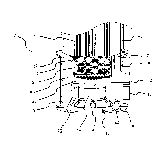
¨
CA 02923986 2016-03-10
differential causes a liquid permeate to be filtered from the liquid and to
flow into the
lumens of the hollow fiber membrane and wherein the permeate from the lumens
is
connected and flows out of the membrane filter.
[0003] A membrane filter of the general type described supra is known from
WO 02/22244-A1 wherein one of the inventors of the instant application was a
co-
inventor.
[0004] The known membrane filter is configured to filter waste water
heavily
loaded with solids that can be found for example in biological waste water
treatment
plants in membrane bioreactors (MBR). Thus, the membrane filter can either be
submerged in the tanks of the waste water treatment plant or it can be set up
on dry
land and provided with inlet and outlet conduits. A driving force for the
filtration is in
many cases implemented by a vacuum applied on a permeate side but can also be
implemented in the dry variant by a small positive pressure on the feed side
with
waste water. The hollow fiber membranes have a diameter of the less than 5mm,
typically 0.5 mm to 3 mm and have a permeability of microfiltration membranes
or
ultra-filtration membranes. Using hollow fiber membranes for reverse osmosis
or
nano filtration is also possible.
[0005] In order to prevent a blocking of the membrane filter with filtered
solids the
membrane filter is flushed continuously or in periodic intervals. Typical
methods for
physical flushing of the membrane filters use permeate side back flushing of
the
hollow fiber membranes with liquid or gas combined with gas bubble flushing on
an
outside of the hollow fiber membranes. The latter introduces gas bubbles from
below into the membrane filter, wherein the gas bubbles then rise along the
hollow
fiber membranes and move the hollow fiber membranes in the liquid to be
filtered.
The rising gas bubbles always also generate an upward flow of the liquid. The
shear
force of the two phase flow including gas and liquid has a high level of
turbulence
which removes coatings from the membranes and flushes them out. The membrane
bioreactors typically use air as gas.
[0006] The so called mammoth pumping effect, this means the upward flow of the
liquid through the membrane filter induced by the rising gas bubbles has a
particularly high cleaning effect upon the hollow fiber membranes when the
hollow
fiber membranes are enveloped by a circumferentially closed tube because this
2
CA 02923986 2016-03-10
keeps the gas bubbles in the membrane filter, this means in direct proximity
to the
hollow fiber membranes. The positive effect of the tube is described among
others
in JP-2003 024937 and US 2006 027 3007 Al.
[0007] In one embodiment of the known membrane filter hollow fiber membranes
of the membrane filter that is useable in a submerged or dry version are
fixated in at
least one membrane carrier which is connected with a tubular shell of the base
element through six attachment locations. The membrane filter includes a
permeate
collecting cavity to which the hollow fiber membranes are connected. The
hollow
fiber membranes are closed individually on top
[0008] Additionally the base element in this membrane filter includes a gas
inlet
which is connected through a gas channel to a mouth piece which protrudes
between the hollow fiber membranes. Through the mouth piece the gas above the
membrane carrier is introduced between the hollow fiber membranes into the
liquid
to be filtered. The mammoth pump effect of the introduced gas suctions the
liquid
from below through six bore holes between the anchor locations of the base
element The bore holes form flow cavities in the base element which are
arranged
between the membrane carrier and the shell. The liquid flows through the
module
base in these flow cavities and then after being mixed with the gas introduced
at a
top of the module base rises together with the gas in the membrane filter,
before the
gas and the liquid flow out of the membrane filter on top. It is
characteristic that the
liquid only flows through the base element through the six bore holes, this
means
flow cavities which are arranged between the shell and the membrane carrier.
There
are no additional pass through openings in the base element for a flow through
of the
liquid. This means the membrane carrier closes the base element besides the
flow
cavities.
[0009] It is furthermore characteristic that the gas and the liquid are
introduced to
the hollow fiber membranes separately, this means the liquid flows through the
flow
cavities between the shell and the membrane carrier from below the membrane
carrier and the gas flows centrally from a mouth piece from above the membrane
carrier to the hollow fiber membranes.
[0010] In the base element in particular the parallel connected flow
cavities
configured as small bore holes for flowing the liquid through are prone to
blocking.
When material is deposited in one of the parallel connected bore holes or when
a
cross section is reduced therein, for example by flushed in leaves or fibrous
3
CA 02923986 2016-03-10
compounds the flow through velocity in the bore hole is reduced and a risk of
additional blocking increases. Such flow through systems of parallel connected
small bore holes are therefore designated as unstable in process engineering.
A
starting blockage in a flow channel self accelerates and leads to a complete
blockage of the respective flow channel if sufficient alternative flow paths
are
available to flow. For example when one of the bore holes in the known
membrane
filter with 6 parallel bore holes starts blocking the remaining five bore
holes can
compensate the reduced flow through. During a complete blockage of the bore
hole
the other bore holes only have to increase their flow through by 20%. The risk
of
blocking parallel connected internally connected channels continuously
decreases
with a decreasing number of channels and increasing channel cross sections.
[0011] Besides the risk of blocking bore holes in the base element there is
another problem in the known membrane filter directly above the attachment
locations. In a flow shadow of the attachment locations there is a risk of
accretion of
particles which can lead to a partial clogging of the filter. The problem of
accumulating particles in less turbulent flow areas is particularly high in
membrane
bioreactors by nature since the liquid to be filtered is a sludge in which
many
particles, hair, fibrous compounds and other contaminants are included which
tend to
form accretions and blockings.
[0012] The third problem of the known membrane filter is insufficient gas
distribution during scale up of the system with a central mouth piece at a top
of the
membrane carrier. The gas bubbles centrally rising in the middle require an
inlet
distance before they grow far enough in size or have horizontally expanded so
that
their reach the entire bundle diameter. With increasing diameter the inlet
distance
becomes longer and it becomes evident that the maximum diameter of the
membrane bundle which can be evenly exposed to the gas is limited to 10 cm at
the
most. Larger diameters have the effect that an outer portion of the bundle
proximal
to the lower clamping location is only insufficiently cleaned by energy of the
introduced air so that blockages are created.
[0013] In the background of the invention also DE 198 119 45A1 describes a
membrane filter which includes a base element with a membrane carrier in which
hollow fiber membranes are attached. Also in this application one of the
instant
inventors was a co-inventor. Herein the membrane filter and the base element
are
enveloped by a common tube. However there is no shell of the base element to
4
CA 2923986 2017-04-24
which the membrane carrier is connected. The membrane filter has a flow cavity
between the membrane carrier and the tube wherein the liquid to be filtered
flows
through the flow cavity. In addition to this flow cavity the membrane filter
includes
additional flow through openings for the liquid to be filtered and the gas in
an interior
wherein the pass through openings are not adjacent to the membrane carrier and
the
tube. In particular these parallel flowed small pass through openings are
problematic
because they are very prone to clogging.
BRIEF SUMMARY OF THE INVENTION
[0014] It is an object of the invention to provide a membrane filter that
has a
reduced clogging propensity.
[0015] Improving upon the known membrane filter it is proposed according to
the
invention that the base element is sequentially flowable from the gas inlet
through
the at least one flow cavity to the outlet thus the gas is not introduced like
in the
known membrane filter through a separate gas conductor centrally to a center
of the
hollow fiber membranes attached in the membrane carrier but the gas supply is
provided together with the liquid through the at least one flow cavity into
the outer
portion of the hollow fiber membranes. This has plural advantages for a
reduction of
a blocking propensity of the membrane filter. On the one hand side a shear
force of
the two phase flow of gas and liquid is also used for flushing the membrane
carrier
and on the other hand side the gas is also introduced into the a peripheral
portion of
the membrane bundle directly in a lower portion of the membranes so that
blocking
propensity may also be reduced here.
[0016] In an embodiment of the membrane filter it is advantageous that the
tube
envelops the hollow fiber membranes at least at 50% of their free length, this
means
its length that is disposed in the liquid. This provides that the mammoth pump
effect
in the tube may generate a sufficiently strong flow in the flow cavity to also
flush
membrane carriers arranged therein.
[0017]
[0018] A membrane bundle with tight packing of the hollow fiber membrane in
a
circular cross section however is limited in diameter. Operations of hollow
fiber
membranes in membrane bioreactors however show that the shear force of the 2
CA 2923986 2017-04-24
phase flow of liquid and gas depending on operating conditions impacts at the
most
2.0 ¨ 2.5 cm into a bundle of hollow fiber membranes. Therefore the outer
diameter
of the membrane bundle with circular cross section is limited to approximately
4 - 5
cm.
[0019]
[0020] The at least one flow cavity includes bulges extending into the
membrane carrier according to the invention. Thus a width of the cross
sectional
surface packed tight with membranes can be reduced to a size which can be
flushed over from an outside due to the shear force of gas and liquid. The
simplest shape of bulges are bulges in a purely radial direction. In view of
the
limitation described supra the diameter of the membrane carrier can be
increased
by the bulges to approximately 8 ¨ 10 cm.
[0021] For larger diameters also other shapes of the bulges and thus
geometries
of the membrane carrier are conceivable like e.g. a clover shape of the
membrane
carrier or a membrane carrier in which plural circular membrane bundles are
arranged.
[0022] In an advantageous embodiment of the membrane filter with a larger
diameter the membrane filter includes fingers which are formed by the bulges
and
which are connected by an anchor of the membrane carrier. The fingers are
advantageously arranged in parallel. The designation finger thus relates to a
feature
in which the fingers grow to a uniform size in a horizontal sectional view
through the
membrane carrier. This however does not mean that the fingers also have a
uniform
size in a vertical orientation or that this height correlates with the width
in any
manner. Thus the fingers provide the option to uniformly configure the width
of the
portion provided with hollow fiber membranes and to select freely. Thus it is
advantageous to configure the width of the portion of the fingers provided
with
membranes in a range between 2 and 5 cm since an optimum flushing of the
portion
of the fingers provided with hollow fiber membranes is then also provided
proximal to
the clamping location.
[0023] It is advantageous to keep the number of anchor locations as small
as
possible since the number of the flow channels for the liquid to be filtered
then
becomes smaller and simultaneously there flow cross sections become larger.
This
may significantly reduce the problem of blocking the parallel flowed flow
channels.
6
CA 02923986 2016-03-10
[0024] When configuring the membrane filter with fingers it is furthermore
advantageous that the membrane carrier is connected with the shell by two
anchor
locations at the most which are arranged in an extension of the anchor. This
has
particular advantages for producing the base element as an injection molded
component.
[0025] In an advantageous embodiment of a membrane filter of this type
according to the invention the membrane carrier is connected with the shell
only
through an anchor location. In this case the entire amount of liquid and gas
flowing
through the membrane filter jointly flows through this one flow cavity and
subsequently flows through its outlet into the tube adjoining on top to the
shell of the
base element. The mammoth pump effect which is generated in particular by the
gas rising in the tube a system of this type can be designated as a quasi-
force flow
system, this means as long as gas rises in the membrane filter liquid is also
suctioned from below from the base element. This means as long as something
flows through the membrane filter the one flow channel is not blocked
completely
and therefore even under partial blocking still has potential to be flushed
clear
through a higher shear force of the flow. A higher shear force can be
implemented
for example by increasing the gas volume and thus the turbulence of the flow.
An
advantage of the option of flushing partially blocked flow channels clear is
not
provided for plural channels that are switched in parallel and internally
flowed. When
a channel is partially blocked for such systems then the channel has the
tendency to
block completely due to the low flow through velocity. In order to clean a
completely
blocked flow channel again mechanical flushing of the membrane filter with a
two
phase flow including gas and liquid typically does not suffice by itself. In
those cases
typically an intense chemical cleaning of the membrane filter or a manual
mechanical
cleaning is required. The option of flushing partially blocked flow channels
clear
increases with a decreasing number of parallel flow channels. Thus selecting a
single flow channel is advantageous. This however is limited in the membrane
filter
according to the invention.
[0026] Implementing only one anchor location in a membrane filter according
to
the invention is only useful up to a diameter of approximately 15 ¨ 18 cm of
the base
element. In larger membrane carriers it is better for static reasons when the
membrane filter includes at least 2 opposite anchor locations. In this
embodiment of
the membrane filter according to the invention it is advantageous to connect
the
7
CA 02923986 2016-03-10
permeate outlet through one anchor location and the gas inlet through another
anchor location.
[0027] For fabrication reasons it is advantageous for the configuration of
the
membrane filter according to the invention with fingers in the membrane
carrier to
configure the width of the portion of the fingers configured with hollow
membranes
on both sides of the anchor and also in the portion of the anchor uniform and
thus
not to configure the small portion between the fingers above the anchor with
membranes.
[0028] In order to prevent that solids are deposited in a flow shadow of
the anchor
between the fingers it is advantageous not to configure the cross section of
the
anchor between the fingers in a vertical direction to the outlet but to let
the cross
section run out in a tapering manner before that. The same applies also for
the
configuration of the anchor locations for connecting the membrane carrier with
the
material.
[0029] In this case the membrane carrier is completely separate from the
shell in
each of the horizontal sectional views above the at least one anchor location,
when
the shell also reaches on top at least up to the upper end of the membrane
carrier
the membrane carrier in this horizontal cross section is completely imbedded
in the
outlet thus the membrane carrier does not have to be continuous above at the
base
element, since in the embodiment of the membrane carrier with fingers and with
an
anchor between the fingers that is not configured to the outlet the cross
section in
the outlet includes plural fingers that are separate from each other which
however
are all part of the membrane carrier.
[0030] Thus it is advantageous according to the invention to also configure
the
width of the bulge of the flow cavity between the fingers in a uniform manner.
This
width however is in a range between 3 mm and 8 mm depending on operating
conditions and solid content of the liquid to be filtered. For a smaller solid
content
and smaller solid particles also smaller dimensions can be useful for
increasing
packaging density under the condition that a sufficient amount of liquid to be
filtered
can flow through the flow cavity.
[0031] In order to make the flow through of the base element even it is
advantageous that the at least one flow cavity in at least one of the
horizontal
sections forms at least one flow channel which has a uniform width over more
than
80% of its length. Since rounding outer edges of the membrane carrier at
locations
8
CA 02923986 2016-03-10
of the bulges is advantageous for flow reasons the width of the flow channel
at these
locations deviates slightly from the uniform width.
[0032] In the embodiment of the membrane filter according to the invention
it is
advantageous that the membrane carrier has a downward tapering cross section
in
the horizontal sectional views. This generates slanted flow leading edges at
the
membrane carrier where contaminants in the liquid to be filtered like e.g.
hair or
fibrous compounds leaves or coarser particles can slide off the bevels are
thus
configured so that the recited contaminants are deflected at the membrane
carrier in
outward direction into the flow cavity. This can be visualized with reference
to the
fingers. When fibrous compounds are applied to the flow leading edge of the
finger
when flowing a finger at the membrane carrier from below then the fibrous
compounds will slide to the end of the finger due to the slanted configuration
of the
flow edge of the fingers and will then slide from the finger into the flow
channel and
will be flushed out of the module. Horizontal exposed flow leading edges where
contaminants can easily lodge are substantially prevented by the configuration
of the
membrane carrier with a downward tapering horizontal cross sectional surface.
[0033] In an advantageous embodiment of the membrane filter the base
element
includes the gas inlet for letting the gas in the base element. The gas inlet
is thus
arranged below the membrane carrier. It is advantageous when the gas inlet is
arranged directly below the membrane carrier because this minimizes a blow in
depth of the gas which has a favorable influence on the energy requirement for
the
gassing.
[0034] Membrane filters known in the art include for example a vertically
oriented
mixing chamber for generating a gas liquid mix. This however has the
disadvantage
that it increases a blow in depth of the gas and thus energy requirements. For
a
water depth of 2 meters an increased blow in depth of 20 cm due to a mixing
chamber already means a 10% higher energy requirement. WO 2008/144 826A1
describes a system of this type with a vertically extending mixing chamber for
mixing
gas and liquid.
[0035] Alternatively the gas inlet lets gas into the base element from
below
without being part of the base element itself.
[0036] It is advantageous for using the membrane filter according to the
invention
for waste water treatment in membrane bioreactors that the hollow fiber
membranes
are individually closed on top and freely float in the flow of the liquid to
be filtered
9
CA 02923986 2016-03-10
with their upper end. Thus contaminants like in particular hair or fibrous
compounds
can be flushed out of the membrane filter even when they have wrapped around
the
hollow fiber membranes when the filter is being flowed through.
[0037] In this embodiment of the membrane filter according to the invention
with
hollow fiber membranes that are only attached in a bottom in the membrane
carrier
of the base element the base element includes a permeate collecting cavity
which is
connected with the lumens of the hollow fiber membranes and the permeate
outlet
for flowing the permeate out of the membrane filter. In this case it is
furthermore
advantageously that the tube with close circumference extends at least up to
the
upper end of the hollow fiber membranes. Advantageously a membrane filter
according to the invention includes a tube which extends above the upper end
of the
hollow fiber membranes. This provides that vertical flow components prevail in
the
upper portion of the hollow fiber membranes which facilitates in particular a
stripping
or flushing of contaminants from the filter.
[0038] For less bending stiff hollow fiber membranes it is advantageous
when the
membrane filter according to the invention includes a head element in addition
to the
base element in which head element the hollow fiber membranes are attached on
top. In a membrane filter of this type according to the invention furthermore
the head
element can include a permeate collecting cavity connected with the lumen of
the
hollow fiber membrane and a permeate outlet. Thus either only the head element
or
additionally also the base element can include a permeate collecting cavity
and a
permeate outlet. The embodiment of a membrane filter according to the
invention
with a respective permeate collecting cavity and a respective permeate outlet
in the
head element and in the base element is more complex from a configuration
point of
view and therefore only useful in a case where the length or the lumen
diameter of
the hollow fiber membranes limit draining the generated permeate due to the
pressure drop in the lumen. Draining the permeate on both sides of the hollow
fiber
membranes tolerates a greater length of the hollow fiber membranes and thus a
smaller diameter of the lumen of the hollow fiber membranes which implements
higher packaging densities in the membrane filter.
[0039] In the embodiment of the membrane filter according to the invention
with a
base element and a head element it is advantageous when the head element has a
membrane carrier with a similar cross section like the base element in an
outlet.
CA 2923986 2017-04-24
[0040] In the embodiment of the membrane filter according to the invention
with a
head element it is useful to purge contaminants from the liquid to a large
extent
before letting it into the membrane filter which in case of membrane
bioreactors is
typically achieved by fine sifting sludge in order to minimize a lodging of
contaminants between the hollow fiber membranes below the head element. For
the
same reason it is useful in this embodiment of the membrane filter according
to the
invention that the tube is not run to the head element with a closed
circumference,
which however is only possible for submerged operations of the membrane
filter.
[0041] The simplest version of a membrane filter according to the invention
in
which the tube is not run to the head element leaves the distance between the
upper
end of the tube and the head element open. Thus the liquid can flow out of the
membrane filter before reaching the head element which reduces the clogging
propensity of the head element. In the configuration of the membrane filter
according to the invention it is advantageous when the tube with close
circumference
which is not run to the head element of the membrane filter is adjoined on top
by a
tube insert with circumferential openings. The openings have the purpose to
let a
portion of the liquid flow out of the membrane filter already before reaching
the head
element. Also this reduces an adherence of hair and fiber compounds below the
head element. It is advantageous to run the tube with closed circumference at
least up
to half the distance between the base element and the head element in order to
use
the mammoth pumping effect and to generate a flow that extends substantially
parallel to the hollow fiber membranes. This avoids furthermore that liquid to
be
filtered flows from an outside over the circumference of the tube which would
lead to
hydrodynamic ally unfavorable transversal flows in the membrane filter. The
tube
and the tube insert can be made from one component.
[0042] Due to the mammoth pumping effect a high flow velocity is already
generated in the base element of the membrane filter according to the
invention.
The combination of the flow of the liquid with the gas flow is already
advantageous to
counter act a blocking of the base element. On the other hand there is a
challenge
to distribute the gas evenly over the cross section of the flow cavity in the
base element. Namely due to the high flow velocity of the liquid to be
filtered gas
bubbles climb directly at the location there introduction into the liquid in a
vertically
upward direction with only minor mixing propensity in horizontal direction.
11
CA 02923986 2016-03-10
[0043] Membrane filters that are known in the art which use the mammoth
pumping effect facilitate a distribution of the gas in the liquid through a
vertically
oriented mixing chamber or inflow zone in which the liquid can also spread in
horizontal direction over the flow cross section. US 5,482,625 describes a
flow end
zone of this type in plate modules with a lateral limitation according to the
tube of the
instant invention. The vertically extending inflow zones or mixing chambers
however
have the disadvantage described supra of higher energy requirements for the
gassing since the gas is introduced with a higher blow in depth.
[0044] The even distribution of the gas over the cross section of the flow
cavity in
the base element is facilitated for an embodiment of the membrane filter
according to
the invention by a gas distribution system for introducing gas at plural
locations
below the membrane carrier into the liquid.
[0045] For a membrane filter according to the invention the membrane
carrier
closes the base element besides the flow cavity not only for the flow through
of the
liquid but also for the flow through of the gas entirely.
[0046] Improving upon the known method it is proposed according to the
invention that the gas flows through the gas inlet into the at least one flow
cavity and
thereafter the gas flows through the base element together with the liquid in
the at
least one flow cavity between the shell and the membrane carrier and through
the
outlet into the tube, wherein the at least one flow cavity includes bulges
protruding
into the membrane carrier according to the invention. A method of this type
according to the invention is performed in a membrane filter according to the
invention and is also characterized by the advantages recited therein.
[0047] In an advantageous embodiment of the method according to the
invention
the liquid and the gas flow around the membrane carrier in at least one of the
horizontal sectional view of the membrane carrier in its entirety. Each
connection
between the membrane carrier and the shell which are designated as anchor
locations in the membrane filter according to the invention bear the risk that
particles
or solids of the liquid deposit in the flow shadow above the connecting
location and
lead to blockages in the portion of the hollow fiber membranes arranged there
above. This is the case in particular when the anchor locations extends
vertically up
to the outlet of the base element in their full width. This risk can be
avoided in that
the anchor locations taper in vertical direction upward and then terminate
already
upstream of the outlet of the base element. In the portion of the taper the
two phase
12
CA 02923986 2016-03-10
flow including gas and liquid can expand into the flow shadow of the anchoring
locations and can thus completely flow around the membrane carrier above the
anchoring locations.
[0048] In order to execute a method according to the invention the membrane
filter can be submerged in the liquid. The membrane filter is then enveloped
by the
liquid and due to the mammoth pumping effect of the gas introduced into the
base
element and rising in the membrane filter the liquid is suctioned from below
into the
base element and flows through the filter unit together with the gas before
both flow
out of the filter unit on top.
[0049] According to method according to the invention the liquid can be
supplied
to the base element by a first liquid conductor and can be run out on top from
the
membrane filter by a second liquid conductor wherein the second liquid
conductor is
connected above the hollow fiber membranes to a tube which envelops the hollow
fiber membranes and adjoins at a top of the base element. This variant of
operating
a filter unit according to the invention is also designated as dry set up
operations.
[0050] According to the method according to the invention due to the tube
adjoining at a top of the shell of the base element the introduced gas
generates a
strong mammoth pumping effect in the membrane filter according to the
invention
which generates in particular also a high flow velocity in the flow cavity of
the base
element. This is an additional drive force in order to flush out deposits and
starting
blockages in the flow cavity self acting.
[0051] When implementing larger filter units plural membrane filters
according to
the invention can be mounted parallel adjacent to each other on a common
frame.
Thus the permeate outlets of the individual membrane filters are connected
with
tubular conduits which are used for running the permeate generated from the
membrane filters. Also the gas inlets are connected with tubular conduits
which are
used for feeding the gas into the membrane filters. Thus the gas feed conduits
are
individually configured with throttles in order to balance the air supply to
the
individual membrane filters. Thus it is advantageous to position the throttles
in the
gas feed conduits above the liquid surface in order to prevent a flooding of
the
throttle cross sections also when the filter is switched off and thus to
exclude a
clogging of the throttles by solid components of the liquid.
Embodiment
13
CA 2923986 2017-04-24
According to an aspect of the present invention, there is provided a
membrane filter for filtering a liquid to be filtered, the membrane filter
comprising:
a base element that is open in a downward direction and includes a tubular
shell and precisely one membrane carrier arranged therein, wherein the
membrane
carrier is connected with the tubular shell through at least one anchor
location, and
wherein a gas and the liquid flow through the base element;
hollow fiber membranes attached on top in the membrane carrier and each
membrane including a lumen into which a liquid permeate is filterable from the
liquid;
a circumferentially closed tube which adjoins the tubular shell at a top end
of
the tubular shell and which envelops the hollow fiber membranes;
a gas inlet for letting the gas into the base element;
at least one permeate collecting cavity which is connected with the lumens of
the hollow fiber membranes for collecting the permeate from the hollow fiber
membranes;
at least one permeate outlet for draining the permeate from the at least one
permeate collecting cavity; and
at least one downward open flow cavity between the shell and the membrane
carrier for flowing the liquid through, wherein the at least one flow cavity
includes an
outlet on top for letting the liquid out into the tube, wherein the at least
one flow
cavity in each horizontal section through the membrane carrier is adjacent to
the
shell and also adjacent to the membrane carrier, and wherein the at least one
flow
cavity envelops the membrane carrier and forms an annular gap, wherein the
annular gap is only interrupted by the at least one anchor location, wherein a
height
of the at least one flow cavity is defined by an overlap portion of a height
of the
membrane carrier and a height of the shell, and wherein the membrane carrier
completely closes the base element besides the at least one flow cavity for a
flow of
the liquid from bottom to top,
wherein the base element is flowable sequentially from the gas inlet through
the at least one flow cavity to the outlet, and
wherein the at least one flow cavity includes bulges extending into the
membrane carrier.
13a
CA 2923986 2017-04-24
According to another aspect of the present invention, there is provided a
method for filtering a liquid in a membrane filter, wherein the membrane
filter
includes:
a base element,
a circumferentially closed tube, and
a gas inlet,
wherein the base element includes a tubular shell, and precisely one
membrane carrier arranged in the base element and connected by at least one
anchor location with the tubular shell,
wherein hollow fiber membranes are attached on top in the membrane
carrier,
wherein the circumferentially closed tube adjoins the tubular shell at a top
end of the tubular shell;
wherein the base element includes at least one flow cavity between the shell
and the membrane carrier,
wherein the at least one flow cavity has an outlet on top leading out of the
base element into the tube,
wherein the at least one flow cavity in each horizontal section through the
membrane carrier is adjacent to the shell and also adjacent to the membrane
carrier,
wherein the at least one flow cavity envelops the membrane carrier and forms
an annular gap, wherein the annular gap is only interrupted by the at least
one
anchor location, wherein a height of the at least one flow cavity is defined
by an
overlap portion of a height of the membrane carrier and a height of the shell,
wherein the membrane carrier completely closes the base element besides
the at least one flow cavity for flowing the liquid from bottom to top,
wherein the liquid flows into the base element and flows through the at least
one flow cavity and then flows around the membrane carrier;
wherein a gas flows through the gas inlet into the base element;
wherein the liquid only flows through the outlet on top of the base element
out
of the base element and only flows through the outlet into the tube;
13b
wherein the gas flows out at a top of the base element into the tube and rises
in the tube and thus generates an upward movement of the liquid in the
membrane
filter;
wherein the rising liquid and the gas flush the hollow fiber membranes on
outer sides of the hollow fiber membranes;
wherein a pressure differential is provided between an outside of the hollow
fiber membranes and lumens of the hollow fiber membranes, wherein the pressure
differential causes a liquid permeate to be filtered out of the liquid and to
flow into the
lumens of the hollow fiber membranes;
wherein the permeate from the lumens is collected and flows out of the
membrane filter,
wherein the gas flows through the gas inlet into the at least one flow cavity,
and subsequently
the gas flows together with the liquid through the base element in the at
least
one flow cavity between the shell and the membrane carrier and flows through
the
outlet into the tube,
wherein the at least one flow cavity includes bulges extending into the
membrane carrier.
Embodiment
13c
CA 2923986 2017-06-01
CA 02923986 2016-03-10
cet No.: MEM001
[0052] The invention is subsequently described based on embodiments with
reference to drawing figures, wherein:
[0053] FIGs. 1a ¨ le illustrate a first embodiment of the membrane filter
(total
sectional view, partial sectional views and views of the base element);
[0054] FIGs. 2a ¨ 2c illustrate flow conditions in the first membrane
filter;
[0055] FIG. 3 illustrates the first membrane filter in submerged
operations;
[0056] FIG. 4 illustrates the first membrane filter in dry set up
operations;
[0057] FIGs. 5a ¨ 5i illustrate details of a second embodiment of the
membrane
filter according to the invention;
[0058] FIGs. 6a ¨ 6c illustrate partial views and sectional views of the
gas
distribution system of the second membrane filter;
[0059] FIGs. 7 a ¨ 7d illustrate additional membrane filters according to
the
invention;
[0060] FIGs. 8a ¨ 8c illustrate details of additional membrane filters
according to
the invention; and
[0061] FIGs. 9a ¨ 9c illustrate membrane carriers of additional membrane
filters
according to the invention.
[0062] The drawing figures are not to scale. All non-stated details of
subsequently described membrane filters according to the invention are
identical
with embodiments of previously described membrane filters according to the
invention.
[0063] FIGs. 1a ¨ le illustrate sectional views and views of a first
membrane filter
1. This membrane filter includes a base element 2 with a shell 3 and a
membrane
carrier 4 arranged therein in which hollow fiber membrane 5 are arranged on
top. A
cylindrical tube 6 adjoins the shell 3 of the base element 2 on top of the
base
element 2.
[0064] The hollow fiber membranes 5 are fabric reinforced and have an external
diameter of 2.5 mm. They are individually closed at an upper end 7. The tube 6
extends beyond the upper end 7 by a length of 8cm to 10 cm. The hollow fiber
membranes 5 are cast in in a sealing manner in the membrane carrier 4 by a
resin
layer 9, wherein lumens of the hollow fiber membrane 5 remain open.
[0065] The membrane filter 1 has a height 10 of 200 cm the base element 2 has
a
height 11 of 12 cm and the membrane carrier 4 has a height 12 of 11 cm. The
base
14
DETE 1-1
¨
CA 02923986 2016-03-10
element 2 and the tube 6 both have an external diameter of 75 mm. The tube 6
has
an internal diameter of 68mm. The base element 2 furthermore includes a gas
inlet
13 and a permeate outlet 14.
[0066] The membrane carrier 4 is connected with the shell 3 through an anchor
location 15. The base element 2 includes a flow cavity 16 between the shell 3
and
the main membrane carrier 4 wherein the flow cavity is configured as an
annular gap
with a width of 9mm, envelops the membrane carrier 4 and is only interrupted
by the
anchor location 15. The flow cavity 16 is adjacent in each horizontal
sectional view
to the shell 3 and also to the membrane carrier 4.
[0067] The flow cavity 16 is limited in vertical direction by the overlap
portion of
the height 11 of the base element 2 and the height 12 of the membrane carrier
4.
The base element 2 is open in downward direction and capable of flow through.
The
flow cavity 16 includes an outlet 17 on top into the tube 6.
[0068] The gas inlet 13 is connected with a gas distribution system 18
configured
on a bottom side of the membrane carrier 4 wherein the gas distribution system
includes a tub 19 that is open in downward direction and closed in upward
direction,
wherein the tub includes a wall 20 with downward open vertical slots 21. The
tub 19
includes an inner edge 22 respectively in a center between adjacent slots 21
in a
sectional view that is vertical and orthogonal to the wall 20, wherein the
inner edge
22 is a slanted edge over an entire height of the slots 21 wherein an angle 24
of the
slanted edge 22 is 40 relative to horizontal. Alternatively the inner edge 22
in a
portion of a lower half 23 of the slots 21 can have an angle 24 relative to
horizontal
that is less than 60 in any point
[0069] The base element 2 furthermore includes a permeate collecting cavity
25
into which the lumens of the hollow fiber membrane lead. The permeate
collecting
cavity 25 is connected with the permeate outlet 14 of the base element 2.
[0070] FIG. 1d illustrates a top view of the base element 2 with the hollow
fiber
membranes 5 without the tube 6. The number of the illustrated hollow fiber
membranes 5 does not correspond to an actual number of the actual hollow fiber
membranes 5. FIG., le illustrates a view of the base element 2 from below. The
number of slots 21 is 6. The slots are evenly distributed over a circumference
of the
top 19 in the wall 20 of the top 19.
[0071] The permeate outlet 14 and the gas inlet 13 are arranged in a
radially
outward extension of the anchor location 15.
CA 02923986 2016-03-10
[0072] FIGs. 2 a ¨ 2c illustrate the flow conditions in the base element 2
and in
the lower portion of the tube 6 of the first membrane filter 1 during
filtering
operations.
[0073] Thus, FIG. 2a illustrates a first vertical sectional view of the
lower portion
of the membrane filter 1, wherein the sectional view also extends through the
anchoring location 15.
[0074] A gas 26 is introduced into the base element 2 and the flow cavity 16
through the gas inlet 13 during operations of the membrane filter 1 thus the
gas 26
flows through the gas inlet 13 initially into the tub 19. The gas 26 fills the
tub 19 up
to a portion of the height of the slots 21 and forms a gas cushion 27 in the
tub. 19.
The gas 26 also fills the slots 21 up to the level of the gas cushion 27 and
eventually
flows laterally through the portion of the slots 21 that are filled with the
gas 26 out of
the tube 19 or out of the gas cushion 27 and thus into a liquid 28 that is to
be filtered.
[0075] Besides the flow cavity 16 the membrane carrier 4 closes the base
element 2 completely for the flow through of the liquid 28 and of the gas 26,
this
means besides the flow cavity 16 there are no additional pass through openings
for
the gas 26 and the liquid 28 in the base element 2.
[0076] Above the base element 2 there are no additional installations in
the tube
6 besides the hollow fiber membranes 5. Therefore the hollow fiber membranes 5
float freely in the liquid 28 without impediment and are only fixated at their
bases.
Thus also hair, fibrous compounds or other contaminants from the liquid 28
cannot
be lodged in this portion.
[0077] During lateral flow through the slots 21 the gas 26 generates a
radially
outward oriented liquid flow that is parallel to the lateral gas flow at a
face boundary
surface below the gas cushion 27. The liquid flows between respective adjacent
slots 21 against and inner edge 22 of the wall 20 which has an angle relative
to
horizontal of less than 600 in each point in the portion of the slots. At this
slanted
inner edge hair and fibrous compounds included in the liquid 28 to be filtered
are
stripped off through the outward oriented gas flow and liquid flow which
reduces a
risk of these contaminants lodging in the membrane filter 1.
[0078] After flowing through the slots 21 the gas 26 rises through its
buoyancy in
the membrane filter 1 and generates an upward flow of the liquid 28. This
liquid flow
is suctioned into the membrane filter only from below. The gas 26 and the
liquid 28
16
CA 02923986 2016-03-10
flow through the flow cavity 16 of the base element 2 and jointly flow through
the
outlet 17 into the tube 6 and above at the tube 6 out of the membrane filter
1.
[0079] The strong shear force effect of the two phase flow including the
liquid 28
and the gas 26 which rises through the mammoth pumping effect in the membrane
filter 1. The membrane carrier 4 is flushed on the outside in the flow cavity
16 of the
base element 2 and the hollow fiber membranes 5 are flushed on the outside in
the
tube 6 and thus coatings and deposits are flushed off from the surfaces of the
membrane carrier 4 and of the hollow fiber membranes 5 and are carried out the
membrane filter 1.
[0080] Between the outside of the hollow fiber membranes 5 and their lumens
there is a pressure differential based on which a liquid permeate 29 is
filtered out the
liquid 28 and flows into the lumens of the hollow fiber membranes 5. The
permeate
29 is collected from the lumens of the hollow fiber membranes 5 and then flows
through the permeate outlet 14 out of the membrane filter 1.
[0081] Through the anchor location 15 the gas 26 is supplied and the
permeate
29 that is filtered in the membrane filter 1 is drained.
[0082] The gas inlet 13 is flow connected with the flow cavity 16 within
the base
element 2, so that the base element 2 is flowable from the gas inlet 13
through the
tub 19, through the slots 21 and through the flow cavity 16 to the outlet 17.
[0083] FIG. 2b illustrates an additional sectional view of the lower
portion of the
membrane filter 1 which sectional view however is turned by 900. Thus the
anchor
location 15 is not sectioned but 2 of the slots 21. The lateral outflow of the
gas 26
through the slots 21 from the tub 19 or from the gas cushion 27 are visible.
Additionally this sectional view shows the permeate collecting cavity 25 but
does not
show the permeate outlet 14.
[0084] FIG. 2c illustrates another sectional view of the lower portion of
the first
membrane filter 1 which in this case only sections the shell 3 and otherwise
extends
through the flow cavity 16 so that the outside of the membrane carrier 4
becomes
visible. Thus the lateral outflow of the gas 26 from the slots 21 is visible.
[0085] FIG. 3 illustrates the first membrane filter 2 is submerged
operations.
Thus gas bubbles in the liquid 28 are not illustrated. Thus the membrane
filter 1 is
submerged in a tank with the liquid 28 to be filtered so that a liquid
overhang 30 of
15 cm remains above the membrane filter 1 to the surface of the liquid 28.
Through
a gas feed conductor 31 the gas 26 is run from above the surface of the liquid
28 to
17
CA 02923986 2016-03-10
the gas inlet 13. A throttle 32 is installed in the gas feed conduit 31. The
throttle is
illustrated at this location in an exemplary manner and is only required when
plural
membrane filters 1 are operated in parallel and supplied with gas 26
simultaneously.
The throttles 32 in the gas feed conduits 31 are used for balancing volumes of
gas
26 flowing into the individual membrane filters 1. The throttle 32 is arranged
above
the surface of the liquid to be filtered. Through a permeate conductor 33 the
permeate 24 generated in the membrane filter 1 is drained by the permeate
outlet
14.
[0086] FIG. 4 illustrates the first membrane filter 1 in dry set up
operation. Gas
bubbles in the liquid 28 to be filtered are thus not illustrated. The liquid
28 is
supplied to the membrane filter 1 through a first liquid conduit 34. A
permeate 29 if
filtered from the liquid 28 and drains through the permeate outlet 14. Through
the
gas inlet 13 the gas 26 is supplied. Through a second liquid conduit 35 the
gas 26
and the liquid 28 minus the permeate 29 are drained. The second liquid conduit
35
is connected at a top of the tube 6 wherein the tube extends beyond the hollow
fiber
membranes 5.
[0087] Figs. 5a - 5g illustrate views and various sectional views of a
second
membrane filter 36 according to the invention.
[0088] FIG. 5a illustrates a longitudinal sectional view of the second
membrane
filter 36. The second membrane filter 36 includes a base element 39 that is
open in
downward direction towards a liquid 37 to be filtered and that is flowable by
a gas 38
and a liquid 37 wherein the base element includes a tubular shelf 40 and
precisely
one membrane carrier 41 arranged therein, wherein the membrane carrier 41 is
connected with the shell 40 through 2 anchor locations 42. Hollow fiber
membranes
43 are attached on top in the membrane carrier 41 wherein the hollow fiber
membranes respectively include a lumen into which a liquid permeate 44 from
the
liquid 37 is filterable. Additionally the membrane filter 36 includes a
circumferentially
closed tube 45 which envelops the hollow fiber membranes 43 and adjoins the
shell
40 or the base element 49 at a top and a gas inlet 46 for letting the gas 38
into the
base element 39. The base element 39 includes a permeate collecting cavity 47
which is connected with the lumens of the hollow fiber membranes 43 collecting
the
permeate 44 from the hollow fiber membranes 43 and a permeate outlet 48 for
draining the permeate 44 from the permeate collecting cavity 47.
18
[0089] The base element 39 has a height 49 of 12 cm and the membrane filter
36
has a height 50 of 212 cm. The hollow fiber membranes 43 are encased at a
bottom
in the membrane carrier 41 by a resin layer 51 against the liquid 37 to be
filtered in a
sealing manner, wherein the lumens of the hollow fiber membranes 43 remain
open.
The number of the illustrated hollow fiber membranes 43 does not correspond to
the
actual number of the hollow fiber membranes 43. The hollow fiber membranes 43
are individually closed on top and flowed freely on top in the liquid 37 to be
filtered
besides the lower fixation. The hollow fiber membranes 43 are completely
enclosed
by the tube 45. The tube 45 protrudes by 10 cm above the upper ends 52 of the
hollow fiber membranes 43.
[0090] FIG. 5b illustrates a top view of the base element 39 of the second
membrane filter 36 and FIG. Sc illustrates a perspective view with a cut up
shell 40.
Between the shell 40 and the membrane carrier 41 the base element 39 includes
a
downward open flow cavity 53 for flowing the liquid 37 to be filtered wherein
the flow
cavity includes an outlet 54 on top for letting the liquid 37 to be filtered
out into the
tube 45.
[0091] The flow cavity 53 has bulges 55 that protruded into the membrane
carrier
41 up to an anchor 56 of the membrane carrier 41. Thus 6 fingers 57 are formed
at
the membrane carrier 41 wherein the 6 fingers are connected by the anchor 56
of
the membrane carrier 41. The 2 anchors 42, are arranged in an extension of the
anchor 56, wherein the gas inlet 46 runs through one anchor location and the
permeate outlet 48 runs through the other anchor location. The two anchor
locations
42 are the only connections of the membrane carrier 41 with the shell 40.
Outfitting
the membrane carrier 41 with the hollow fiber membranes 43 is performed in the
second membrane filter 36 only in the portion of the fingers 57, wherein the
portion
between the fingers above the anchor 56 remains recessed for production
reasons.
The hollow fiber membranes 43 of the second membrane filter 36 are fabric
reinforced and have an outer diameter of 2.5 mm.
[0092] In the portion of the anchor 56 there is a horizontal section in the
base
element 39 in which the flow cavity 53 forms two continuous flow channels 58
which
have a uniform width 59 of 6mm in the annular gap in the outer portion of the
fingers
57. Also between the fingers 57 the flow channel 58 has the same width 59 of
six
mm. Since the edges of the fingers 57 are rounded for hydrodynamic reasons the
2
flow channels 58 have a slightly greater width than 6mm at the edges of the
fingers
19
Date Recue/Date Received 2021-02-10
CA 02923986 2016-03-10
57. Overall the 2 flow channels 58 have a uniform width of 6 mm on more than
80%
of their length.
[0093] The flow cavity 53 in each horizontal section is adjacent to the
shell 40 and
also adjacent to the membrane carrier 41 and is only interrupted by the two
anchor
locations. The membrane carrier 41 closes the base element 39 completely
besides
the flow path 53, this means the base element 39 has no additional flow
through
channels besides the flow cavity 53 for the liquid 37 to be filtered for the
gas 38.
[0094] The diameter 60 of the base element 39 of the second membrane filter 36
is approximately 208 mm.
[0095] FIG. 5d illustrates a sectional view of the base element 39 of the
second
membrane filter 36 so that the anchor 56 is cut precisely in the flow cavity
53
between two fingers 57. Within the anchor 56 there is a portion of the
permeate
collecting cavity 47. The flow cavity 53 is defined in vertical direction by
the overlap
portion of the height 49 of the base element 39 and a height 61 of the
membrane
carrier 41. At the bottom side of the membrane carrier 41 a gas distribution
system
62 is formed whose height remains unconsidered when defining the flow cavity
53.
The flow cavity 53 terminates on top in the outlet 54.
[0096] As evident from FIG. 5d and 5e the fingers 57 are provided with a bevel
on
a bottom in both horizontal direction wherein the membrane carrier 41 has a
horizontal cross sectional surface that decreases in the downward direction.
Thus
hair and fibrous compounds included in the liquid 57 to be filtered so not
adhere to
the fingers 57 but are stripped off along the bevel of the fingers 57 into the
flow
cavity 53, flushed through the flow cavity 53 and subsequently move into the
portion
of the hollow fiber membranes 43 in the tube 45. Since no other installations
are
provided in this portion besides the hollow fiber membranes 43 that are
individually
closed on top and at which hair or fibrous compounds can adhere and
additionally
since the hollow fiber membranes 43 are individually closed on top hair and
fibrous
compounds can be flushed freely in upward direction out of the membrane filter
36.
[0097] FIG. 5f illustrates a perspective view of the base element 39 of the
second
membrane filter 36 at a slant angle from below and FIG. 5g illustrates a half
of the
base element 39 with a cut up shell 40.
[0098] In the second membrane filter 36 the base element 39 includes the
gas
inlet 46. The gas inlet 46 is connected with a gas distribution system 62
formed at a
bottom side of the membrane carrier 41 wherein the gas distribution system 62
CA 02923986 2016-03-10
includes a downward open and upward closed tube 63 which includes a wall 64
with
downward open vertical slots 65 for distributing the gas 38 into the liquid 37
to be
filtered. The width of the tub 63 corresponds to the width of the anchor 56
and is
formed at its lower side. The gas inlet 46 adjoins laterally directly at the
tub 63.
[0099] At each second slot 65 a gas conducting channel 66 is externally
connected to the tub 63 wherein the gas conducting channel is configured at a
bottom side of the finger 57 for conducting the gas 38 away from the tub in a
direction towards the shell 40. The other slot 65 at which no gas conducting
channel
66 are connected respectively open between two fingers 57 or for the outer
fingers
57 between the fingers 57 and the shell 40 on an outside of the anchor 56.
Thus the
tub 63 has a wall 64 on each of its 2 longitudinal sides wherein the wall 64
respectively includes 13 slots 65. The slot 65 become wider in downward
direction
in order to also be able to compensate larger variations in the amount of gas
that is
being supplied.
[00100] The width of the slots 65 and thus also their cross sectional
surface
have different sizes. Thus the volume of the gas 38 is adapted to the surface
of the
hollow fiber membranes 43 flowing through the slots 65. Accordingly the slots
65
include wider slots 65 below the longer fingers 67 in a center of the base
element 39
then the outer slots 65 below the shorter fingers 57. The narrowest slots 65
are the
slots that open between the fingers 57. Through the configuration of the gas
distribution system 62 with slot 65 and gas conduction channels 66 the gas 38
flows
around the membrane carrier 41 after flowing in the liquid 37 to be filtered.
[00101] The base element 39 is flowable from the gas inlet 46 through the
wall
63 through the slots 65 and through the flow cavity 53 to the outlet 54. The
membrane carrier 41 closes the base element 39 besides the flow cavity 53 not
only
for the flow through of the liquid 37 to be filtered but also for the flow
through of the
gas 38.
[00102] FIG. 5h illustrates only one of the fingers 57 of the second
membrane
filter 36. Thus the anchor 56 is visible in a sectional view as well as the
tub 63
formed on its bottom side. Furthermore gas conducting channels 66 are visible
on a
bottom side of the finger 57, wherein the gas conducting channels 66 extend on
both
sides of the tub 63.
21
_
CA 02923986 2016-03-10
[00103] FIG. 5i shows a sectional view of the gas conducting channel 66 in
the base element 39 of the second membrane filter 36. Thus it is evident that
the
gas conducting channel 66 adjoin the slots 65 vertically offset in upward
direction.
[00104] FIGs. 6 a ¨ 6c illustrate views and sectional views of elements of
the
tub 63 of the second membrane filter 36.
[00105] The tub 63 includes vertical ribs 67 respectively extending in a
center
between adjacent slots 65 orthogonal to the wall 64. Each rib 67 includes a
taper at
a bottom which runs towards the wall 64 and thus forms a slanted or rounded
inner
edge 68 of the tub 63.
[00106] Geometrically speaking the tub 63 includes an inner edge 68
respectively extending between adjacent slots 65 in a vertical sectional view
wherein
the vertical sectional view in this case extends orthogonal to the wall 64
through the
rib 67 wherein the inner edge at least in a portion of a lower half 69 of the
slot 65
includes in every point an angle 70 relative to horizontal of less than 600 at
a level of
the half 69 of the slots 65 of 58 . The non illustrated filtration operations
of the
second membrane filter 56 differs from filtrations operations of the first
membrane
filter 1 as follows.
[00107] The gas 38 flows through the gas inlet 46 into the tub 63 and fills
the
tub 63 and the slots 65 up to a portion of the height of the slot 65 with a
gas cushion.
From the gas cushion the gas 38 flows through the slot 65 in laterally outward
direction from the tub 63 and thus at plural locations below the membrane
carrier 41
into the liquid 37 to be filtered. Thus the gas 38 flows out of the slot 65
into bulges
55 of the flow cavity 53 respectively between two fingers 57 and on the other
hand
side out of the slot 65 below the finger 57 into the gas conduction channel
66.
Through the gas conduction channel 66 the gas 38 flows in outward direction
further
away from the tub 63 into the outer portion of the membrane filter 36.
[00108] During lateral flow through the slots 65 a liquid flow that is
oriented
parallel to the lateral gas flow is generated at the face boundary below the
gas
cushion wherein the liquid flow flows against the inner edge 68 of the rib 67.
Based
on the angle 70 of the inner edge 68 of the tub 63 which is arranged between
two
slots 65 hair and fibrous compounds can be stripped off when the inner edge 68
is
exposed to a flow which significantly reduces a clogging propensity of the
membrane
filter 36.
22
CA 02923986 2016-03-10
[00109] After the gas enters the liquid 37 to be filtered the membrane
carrier 41
is flowed by the gas 38 and the liquid 37 before the mix from gas 38 and
liquid 37
flows around the hollow fibers membranes 43 attached at a top in the membrane
carrier 41. Due to the high shear force of the two phase flow the hollow fiber
membranes and the membrane carrier 41 are flushed on an outside.
[00110] The base element 39 is flowed by the gas 38 starting from the gas
inlet
46 through the tub 63 through the slot 65 and through the flow cavity 53 to
the outlet
54. Since the flow cavity 53 is always arranged between the shell 40 and the
membrane carrier 41 and furthermore protrudes through the bulges 55 also into
the
inner portion of the membrane filter 36 this generates even gassing of the
membrane
filter 36 over the entire cross section while avoiding a flow through of small
parallel
connected flow cavities. Thus over all the blocking propensity of the membrane
filter
36 is reduced compared to what is known in the art.
[00111] Also the second membrane filter 36 can be set up for submerged
operations or dry operations.
[00112] FIG. 7a ¨ d illustrate additional variants of membrane filters
according
to the invention with a base element and a head element.
[00113] FIG. 7a illustrates a third membrane filter 71 according to the
invention.
This membrane filter differs from a first membrane filter 1 in that a base
element 72
is adjoined on top by a closed tube 73 which envelops the hollow fiber
membrane 74
and which adjoins at a head element (75) on top. The head element 75 includes
a
shell 76 and a membrane carrier 77, included therein wherein the membrane
carrier
77 is connected with the shell 76 only through an anchor location 78. In the
head
element 75 the hollow fiber membrane 74 are encased and attached on top by a
resin layer 79 in a sealing manner relative to the liquid to be filtered with
their lumens
in an open manner.
[00114] The head element 75 includes a permeate collecting cavity 80 which
is
flow connected with the lumens of the hollow fiber membranes 74 for collecting
the
permeate and a permeate outlet 81 for draining the permeate. Furthermore the
head
element 75 includes a second flow cavity 82 for flowing the gas and the liquid
to be
filtered and flowing out of the head element 75. The third membrane filter 71
can be
used in submerged operations and in dry set up operations.
[00115] FIG. 7b illustrates a fourth membrane filter 83 according to the
invention. The fourth membrane filter differs from the third membrane filter
71 in
23
that a tube 84 which adjoins at a base element 85 on top is adjoined on top
initially
by a tube insert 86 with openings 87 for lateral outflowing of a portion of
the gas and
of the liquid to be filtered from the tube 84. The tube insert 86 and the tube
84 are
made for the fourth membrane filter 83 form one piece. A head element 88
adjoins
on top to the tube insert 86 wherein the head element 88 has the same details
as the
head element 75 of the third membrane filter 71. The base element 85 forms
another difference to the third membrane filter 71 wherein the base element 85
does not have any permeate collecting cavity, this means the hollow fiber
membranes 74 are closed at a bottom and encased with resin in the base element
85 and fixated. The permeate generated in the hollow fiber membranes 39 only
flows into the permeate collecting cavity 90 of the head element 88, is
collected
therein and flows through a permeate outlet 91 from the fourth membrane filter
83.
This fourth membrane filter 83 can only be used in submerged operations due to
the
openings 87 in the tubular insert 86.
[00116] FIG. 7c illustrates a fifth membrane filter 92 according to the
invention.
The fifth membrane filter differs from the third membrane filter 71 in that
the tube 93
is not run to the head element 94 but terminates even earlier with a tubular
expansion 95 on top. Thus the head element 93 is not connected with the tube
93
and is accordingly not configured flowable for the liquid to be filtered and
the gas.
Therefore it only includes one membrane carrier 96 with hollow fiber membranes
98
that are resin connected and open towards a permeate collecting cavity 97 and
a
permeate outlet 99 adjoining the permeate collecting cavity 97 for collecting
and
draining a portion of the permeate generated from the hollow fiber membranes
98.
The other portion of the permeate is drained from a base element 100 that is
identical to the base element of the third membrane filter 71. Also the fifth
membrane filter 92 can only be used in submerged operation due to the open
configuration between the tube 93 and the head element 94.
[00117] FIG. 7d illustrates a sixth membrane filter 101 according to the
invention. The sixth membrane filter 101 respectively includes a base element
102
and a head element 103 which are identical to the respective elements of the
fourth
membrane filter 83 and which are connected through a continuously closed tube
104. The sixth membrane filter 101 according to the invention is configured
for dry
operations. Thus a first liquid conduit 105 is connected to the base element
102 for
letting the liquid to be filtered flow from below into the base element 102.
24
Date Recue/Date Received 2021-02-10
CA 02923986 2016-03-10
Furthermore a second liquid conduit 106 adjoins the head element 103 for
letting out
the liquid and the gas from the sixth membrane filter 101.
[00118] FIGS. 8a ¨ 8c illustrate sectional views through base elements of
three
additional membrane filters according to the invention with variants of the
gas inlet
and the height of the flow cavity which is formed from the overlap portion of
the
heights of the shell and membrane carrier.
[00119] FIG. 8a illustrates a sectional view through a base element 107 of
a
seventh membrane filter according to the invention in which the base element
107
includes a gas inlet 108 which is continued on an inside of the shell 109 as a
tubular
spout 110 towards the center of the base element 107 where the gas flows out
centrally below a membrane carrier 111 and subsequently flows around the
membrane carrier. The shell 109 of the base element 107 protrudes beyond the
membrane carrier 117 on top and at a bottom so that the height 112 of the flow
cavity defined by the intersecting portion of the heights of shell 109 and
membrane
carrier 111 is identical in this case with the height of the membrane carrier
111.
[00120] FIG. 8b illustrates a sectional view of the base element 113 of an
eighth membrane filter according to the invention in which the base element
113
does not include a gas inlet 114. The gas is fed herein separately from the
base
element 113 from below centrally below the membrane carrier 115 through the
gas
inlet 114 and subsequently flows around the membrane carrier 115. The
dimensions
of the shell 116 of the base element 113 are flush on top and on the bottom
with the
dimensions of the membrane carrier 115 so that the height 117 of the flow
cavity
coincides in this case with the height of the membrane carrier 115 and the
height of
the shell 116. FIG. 8c illustrates a sectional view of a base element 118 of a
ninth
membrane filter according to the invention in which the gas inlet 119 is
identical with
the gas inlet of the eighth membrane filter according to the invention, the
membrane
carrier 120 of the base element 118 protrudes at a top and at a bottom beyond
the
shell 121 so that the height 122 of the flow cavity that is defined in this
case by the
overlapping portion of the heights of the membrane carrier 120 and the shell
121 is
identical in this case with the height of the shell 121.
[00121] FIGs. 9a ¨ 9c illustrates variants of the shape of the membrane
carrier
in additional membrane filters according to the invention. These variants can
be
implemented in particular in all previously described membrane filters.
CA 02923986 2016-03-10
[00122] FIG. 9a illustrates a base element 123 of a tenth membrane filter
according to the invention which includes a shell 124 with a membrane carrier
126
arranged therein that is connected with the shell 124 only through an anchor
location
125. Between the shell 124 and the membrane carrier 126 there is a flow cavity
127
with bulges 128 into the membrane carrier 126. The membrane carrier 126 closes
the base element 123 besides the flow cavity 127 entirely for the flow through
of the
gas and the liquid to be filtered.
[00123] FIG. 9 b illustrates a base element 129 of an eleventh membrane
filter
according to the invention which includes a shell 130 with a membrane carrier
132
arranged therein and connected to the shell 130 only through an anchoring
location
131. The membrane carrier 132 includes 7 membrane bundles 133 wherein 6
membrane bundles are arranged similar to a blossom structure about a central
membrane bundle 133. Between the shell 130 and the membrane carrier 132 there
is a flow cavity 134. The membrane carrier 132 closes the base element 129
completely for the flow through of the gas and the liquid to be filtered
besides the
flow cavity 134.
[00124] FIG. 9c illustrates a base element 135 of a twelfth membrane filter
according to the invention which includes a shell 136 with a membrane carrier
138
arranged therein and connected with the shell 136 only through an anchoring
location 137 wherein the membrane carrier includes 4 fingers 139 that are
connected
with one another through an anchor 140 and which are attached at the anchor
location 137. Between the shell 136 and the membrane carrier 138 there is a
flow
cavity 141 with bulges 142 and to the membrane carrier 138 which reach to the
anchor 140. The membrane carrier 138 closes the base element 135 besides the
one flow cavity 141 completely for a flow through of the gas and of the liquid
to be
filtered.
26
CA 02923986 2016-03-10
REFERENCE NUMERALS AND DESIGNATIONS
[00125] 1 membrane filter
[00126] 2 base element
[00127] 3 shell
[00128] 4 membrane carrier
[00129] 5 hollow fiber membrane
[00130] 6 tube
[00131] 7 upper end
[00132] 8 length
[00133] 9 resin layer
[00134] 10 height membrane filter
[00135] 11 height base element
[00136] 12 height membrane carrier
[00137] 13 gas inlet
[00138] 14 permeate outlet
[00139] 15 anchor location
[00140] 16 flow cavity
[00141] 17 outlet
[00142] 18 gas distribution system
[00143] 19 tub
[00144] 20 wall
[00145] 21 vertical slot
[00146] 22 inner edge
[00147] 23 lower half
[00148] 24 angle
[00149] 25 permeate collecting cavity
[00150] 26 gas
[00151] 27 gas cushion
[00152] 28 liquid to be filtered
[00153] 29 permeate
[00154] 30 liquid overhang
[00155] 31 gas feed conduit
[00156] 32 throttle
[00157] 33 permeate conduit
27
CA 02923986 2016-03-10
[00158] 34 first liquid conductor
[00159] 35 second liquid conductor
[00160] 36 membrane filter
[00161] 37 liquid to be filtered
[00162] 38 gas
[00163] 39 base element
[00164] 40 shell
[00165] 41 membrane carrier
[00166] 42 anchor location
[00167] 43 hollow fiber membrane
[00168] 44 permeate
[00169] 45 tube
[00170] 46 gas inlet
[00171] 47 permeate collecting cavity
[00172] 48 permeate outlet
[00173] 49 height
[00174] 50 height
[00175] 51 resin layer
[00176] 52 upper end
[00177] 53 flow cavity
[00178] 54 outlet
[00179] 55 bulge
[00180] 56 anchor
[00181] 57 finger
[00182] 58 flow channel
[00183] 59 width
[00184] 60 diameter
[00185] 61 height
[00186] 62 gas distribution system
[00187] 63 tub
[00188] 64 wall
[00189] 65 slot
[00190] 66 gas conducting channel
[00191] 67 rib
28
CA 02923986 2016-03-10
[00192] 68 inner edge
[00193] 69 half
[00194] 70 angle
[00195] 71 membrane filter
[00196] 72 base element
[00197] 73 tube
[00198] 74 hollow fiber membrane
[00199] 75 head element
[00200] 76 shell
[00201] 77 membrane carrier
[00202] 78 anchor location
[00203] 79 resin layer
[00204] 80 permeate collecting cavity
[00205] 81 permeate outlet
[00206] 82 flow cavity
[00207] 83 membrane filter
[00208] 84 tube
[00209] 85 base element
[00210] 86 tube insert
[00211] 87 opening
[00212] 88 head element
[00213] 89 hollow fiber membrane
[00214] 90 permeate collecting cavity
[00215] 91 permeate outlet
[00216] 92 membrane filter
[00217] 93 tube
[00218] 94 head element
[00219] 95 tube expansion
[00220] 96 membrane carrier
[00221] 97 permeate collecting cavity
[00222] 98 hollow fiber membrane
[00223] 99 permeate outlet
[00224] 100 base element
29
CA 02923986 2016-03-10
[00225] 101 membrane filter
[00226] 102 base element
[00227] 103 head element
[00228] 104 tube
[00229] 105 first liquid conductor
[00230] 106 second liquid conductor
[00231] 107 base element
[00232] 108 gas inlet
[00233] 109 shell
[00234] 110 tubular spout
[00235] 111 membrane carrier
[00236] 112 height
[00237] 113 base element
[00238] 114 gas inlet
[00239] 115 membrane carrier
[00240] 116 shell
[00241] 117 height of the flow cavity
[00242] 118 base element
[00243] 119 gas inlet
[00244] 120 membrane carrier
[00245] 121 shell
[00246] 122 height of flow cavity
[00247] 123 base element
[00248] 124 shell
[00249] 125 anchor location
[00250] 126 membrane carrier
[00251] 127 flow cavity
[00252] 128 bulge
[00253] 129 base element
[00254] 130 shell
[00255] 131 anchor location
[00256] 132 membrane carrier
[00257] 133 membrane bundle
[00258] 134 flow cavity
CA 02923986 2016-03-10
[00259] 135 base element
[00260] 136 shell
[00261] 137 anchor location
[00262] 138 membrane carrier
[00263] 139 finger
[00264] 140 anchor
[00265] 141 flow cavity
[00266] 142 bulge
31