Note: Descriptions are shown in the official language in which they were submitted.
CA 02924143 2016-03-11
WO 2015/036306
PCT/EP2014/068784
DESCRIPTION
Securing element and assembly system for securing an
attachment part to a C-rail
The invention relates to a securing element for a C-
rail and to an assembly system for fastening an
attachment part to the C-rail.
C-rails, in which two laterally arranged limbs are
arranged on a base plate and two holding strips which
are spaced apart from one another are arranged on said
limbs, are usually used for exchangeably fastening
attachment or installation parts, for example, to a
vehicle. Here, the respective attachment part is
pressed onto the C-rail which is arranged fixedly
(screwed or welded) on the vehicle, against the outer
faces of the two holding strips of the C-rail, by means
of an assembly system which comprises a bolt
connection.
As a rule, a headed bolt and a slide nut which is
arranged in the interior space of the C-rail are used
as bolt connection. In the case of the use as intended
of the assembly system, the bolt head then bears
against the attachment part on the outer side directly
or via a washer, and the bolt shank extends through the
attachment part and is screwed into the slide nut which
is supported on the inner faces of the holding strips
of the C-rail.
As an alternative, a T-head bolt and a nut can also be
used as bolt connection. Here, in the case of the use
as intended of the assembly system, the bolt head of
the T-head bolt is supported on the inner faces of the
holding strips of the C-rail, whereas the bolt shank is
screwed into the nut which is supported directly or via
a washer on the outer side of the attachment part.
CA 02924143 2016-03-11
WO 2015/036306
PCT/EP2014/068784
- 2 -
It has proven disadvantageous in assembly systems which
are known in this way that the commercially available
C-rails can be bent open relatively easily under load,
in particular high loads, and the attachment parts can
then be ripped out of the C-rail together with the bolt
connection.
In order to make it more difficult for the C-rails to
be bent open in this way under load, C-rails have been
disclosed, in which the holding strips in each case
have an oblique profile which is directed toward the
interior space of the C-rail. The assembly systems
which are used in this case comprise an intermediate
part (counterpiece) which is arranged between the slide
nut or the head of the T-head bolt and the attachment
part, the slide nut or the bolt head of the T-head bolt
and the intermediate part having a contour which is
adapted to the holding strips on their sides which face
the holding strips. During the connection of the
attachment part to the C-rail, the holding strips are
then also at the same time clamped in between the slide
nut or the head of the T-head bolt and the
ccunterpiece.
It has also been shown in practice in the case of said
assembly systems that the C-rail can be bent open under
high loads which are possibly also associated with a
rapid direction change.
The invention is based on the object of specifying an
assembly system, by way of which attachment parts can
be fastened to a C-rail, bending open of the C-rail
under high load being avoided or being made
substantially more difficult in comparison with known
assembly systems.
81795451
- 3 -
In some embodiments disclosed herein, there is provided a C-rail
which has two laterally arranged limbs and two holding strips
which are spaced apart from one another having at least one
securing element which is bracket-shaped and comprises two limbs,
wherein the two holding strips of the C-rail both have an oblique
course which is directed toward an interior space of the C-rail,
wherein the two limbs of the at least one securing element at
least partially engage around an outer side of the two laterally
arranged limbs and the two holding strips of the C-rail which are
spaced apart from one another, wherein the securing element can
be connected to the C-rail via a bolt connection, wherein the
bolt connection comprises a headed bolt and a slide nut or a T-
head bolt and a nut, wherein an intermediate part is arranged
between the slide nut or a bolt head of the T-head bolt and the
securing element, and wherein the slide nut or the bolt head of
the T-head bolt and the intermediate part have a contour which is
adapted to the holding strips on sides of the slide nut or the
bolt head of the T-head bolt and the intermediate part which face
the holding strips.
In some embodiments disclosed herein, there is provided an
assembly system for fastening an attachment part to a C-rail
which has two laterally arranged limbs and two holding strips
which are spaced apart from one another and face the attachment
part, wherein an intermediate part is pressed against outer faces
of the two holding strips of the C-rail by means of a bolt
connection, wherein the C-rail has a securing element which is
bracket-shaped, wherein the securing element is connected to the
C-rail via the bolt connection, wherein the bracket-shaped
securing element being arranged between the attachment part and
the holding strips with the result that the two limbs of the
bracket-shaped securing element at least partially engage around
CA 2924143 2018-12-19
81795451
- 3a -
the outer sides of the two laterally arranged limbs of the
C-rail, wherein the bolt connection comprises a headed bolt and a
slide nut, a bolt head of the headed bolt bearing directly or via
a washer on the outer side of the attachment part, and a bolt
shank of the headed bolt being guided through the attachment part
and through the securing element and being screwed into the slide
nut which is supported on inner faces of the holding strips of
the C-rail, or wherein the bolt connection comprises a T-head
bolt and a nut, the bolt head of the T-head bolt being supported
on the inner faces of the holding strips of the C-rail, and a
bolt shank of the T-head bolt being guided through a gap which is
situated between the two holding strips and through the
attachment part and being screwed into the nut which is supported
directly or via a washer on the outer side on the attachment
part, and wherein the C-rail having the two holding strips which
both have an oblique course which is directed toward an interior
space of the C-rail, the intermediate part is arranged between the
slide nut or the bolt head of the T-head bolt and the securing
element, the slide nut or the bolt head of the T-head bolt and the
intermediate part having a contour which is adapted to the holding
strips on sides of the slide nut or the bolt head of the T-head
bolt and the intermediate part which face the holding strips.
The invention is based substantially on the concept of using a
bracket-shaped securing element which, in the case of the use as
intended of the assembly system, is arranged between the
attachment part and the holding strips in such a way that the two
limbs of the bracket-shaped securing element at least partially
engage around the outer side of the two laterally arranged limbs
of the C-rail and, as a result, prevent bending open of the
C-rail under load or at least make it substantially more
difficult. The additionally incorporated "hasp" preferably
CA 2924143 2018-12-19
81795451
- 3b -
locally clasps the C-rail and supports the lateral limbs of the
C-rail. A plurality of hasps or securing elements can also be
attached in a manner which is distributed over the length of the
C-rail, even at locations where no attachment part is provided.
This measure can increase the stability of the C-rail over its
length.
Here, the securing element has to consist of a material of
corresponding strength (for example, steel) and has to have a
wall thickness which ensures sufficient flexural stiffness.
It is not absolutely necessary that the limbs of the securing
element and the limbs of the C-rail are in contact with one
another, but rather it can certainly be advantageous for the
assembly if there is a slight play between said parts and the
securing element exerts its effect only when the limbs of the
C-rail have bent open slightly.
CA 2924143 2018-12-19
CA 02924143 2016-03-11
* WO 2015/036306
PCT/EP2014/068784
- 4 -
Once again, for example, a headed bolt with a slide nut
or a T-head bolt with a simple nut can be used as bolt
connections.
The assembly system according to the invention can also
be used in the case of C-rails having holding strips
which in each case have an oblique course which is
directed toward the interior space of the C-rail, and
in the case of which the holding strips are also at the
same time clamped in between the slide nut or the head
of the T-head bolt and the counterpiece during the
connection of the attachment part to the C-rail.
Further details and advantages of the invention result
from the following exemplary embodiments which are
explained using figures, in which:
fig. 1 shows the
cross section through a C-rail, to
which an attachment part is fastened by means
of a first exemplary embodiment of an
assembly system according to the invention,
and
fig. 2 shows a
view which corresponds to fig. 1,
with a second exemplary embodiment of an
assembly system according to the invention.
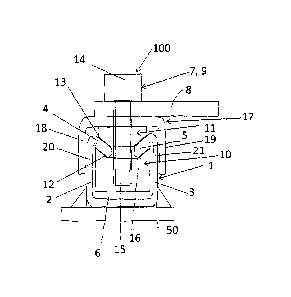
In fig. 1, 1 denotes a C-rail which, for example, is
welded, screwed, etc. to a vehicle (vehicle
housing/vehicle hull 50). The C-rail 1 has two
laterally arranged limbs 2, 3 and two holding strips 4,
5 which are spaced apart from one another and are
arranged on the limbs 2, 3. Here, the holding strips 4,
5 in each case have an oblique course which is directed
toward the interior space 6 of the C-rail 1.
CA 02924143 2016-03-11
WO 2015/036306
PCT/EP2014/068784
- 5 -
An attachment part 8 is fastened to the C-rail 1 with
the aid of an assembly system 100 which comprises a
bolt connection 7. Here, the bolt connection 7 consists
substantially of a headed bolt 9 and a slide nut 10 and
an intermediate part 11. The slide nut 10 and the
intermediate part 11 in each case have an obliquely
running contour 12, 13 which is adapted to the holding
strips 4, 5 on their sides which face the holding
strips 4, 5.
The bolt head 24 bears on the outer side of the
attachment part 8, whereas the bolt shank 15 of the
headed bolt 9 is guided through the attachment part 8
and the intermediate part 11 and is screwed into the
slide nut 10 which is supported on the inner faces 16
of the holding strips 4, 5 of the C-rail 1.
It is then provided according to the invention that the
assembly system 130 comprises, in addition to the bolt
connection 7, a bracket-shaped securing element 17
which is fixed by way of the bolt connection 7 between
the attachment part 8 and the intermediate part 11.
Here, the two limbs 18, 19 of the bracket-shaped
securing element 17 engage around outer sides of upper
part regions 20, 21 of the two laterally arranged limbs
2, 3 of the C-rail 1 and therefore prevent the lateral
limbs 2, 3 of the C-rail 1 from bending open under
load. The limb 8 and the securing element 17 can be in
one piece or can be connected fixedly to one another.
This assembly simplification can also be extended to
the intermediate part 11, with the result that the
intermediate part 11 and the securing element 17 are in
one piece, or are at least connected fixedly to one
another, in the preferred embodiment of the limbs 8.
Fig. 2 shows an exemplary embodiment which corresponds
to fig. 1 and in which the assembly system 100'
CA 02924143 2016-03-11
WO 2015/036306
PCT/EP2014/068784
- 6 -
comprises a bolt connection 7' which consists of a T-
head bolt 22 and a nut 23. The bolt head 24 of the T-
head bolt 22 is supported on the inner faces 16 of the
holding strips 4, 5 of the C-rail 1, and the bolt shank
25 is guided through the gap 26 which is situated
between the two holding strips 4, 5, the intermediate
part 11, the securing element 17 and the attachment
part 8 and is screwed into the nut 23 which is
supported on the outer side of the attachment Dart
(limb) 8 via a washer 27.
It goes without saying that the invention is not
restricted to the above-described exemplary
embodiments. For instance, the securing element 17 can
also be used in assembly systems, in which the holding
strips of the C-rail are arranged horizontally and an
intermediate part is dispensed with. In this case, the
securing element 17 is supported directly between the
attachment part and the outer faces 28 of the holding
strips 4, 5 of the C-rail 1.
It goes without saying that relatively small
modifications are possible within the context of the
invention. For instance, the assembly system 100, 100'
can also serve without an attachment part 8 as a
securing means for the C-rail per se. Here, the
securing element 17 serves for a C-rail 1. By way of
the two limbs 18, 19, the bracket-shaped securing
element 17 at least partially encloses the outer side
of the two laterally arranged limbs 2, 3 and the two
holding strips 4, 5 of the C-rail 1 which are spaced
apart from one another. The securing element 17 can be
connected, that is to say fastened, to the C-rail 1 via
the bolt connection 7, 7' as described in the assembly
system 100, 100'. Here too, the bolt connection 7, 7'
can comprise a headed bolt 9 and a slide nut 10 or a T-
head bolt 22 and a nut 23. In the case of a C-rail 1
CA 02924143 2016-03-11
WO '2015/036306
PCT/EP2014/068784
- 7 -
having holding strips 4, 5 which in each case have an
oblique course which is directed toward the interior
space 6 of the C-rail 1, an intermediate part 11 is
arranged between the slide nut 10 or the bolt head 24
of the T-head bolt 22 and the securing element 17, as
is also the case in the assembly system 100, 100' (no
separate illustration, since it can be aathered from
the figure).
CA 02924143 2016-03-11
W0.2015/036306
PCT/EP2014/068784
- 8 -
List of Designations
C-rail
2, 3 Limb (C-rail)
4, 5 Holding strips
6 interior space
7, 7' Bolt connections
8 Attachment part
9 Headed bolt
10 Slide nut
11 Intermediate part
12, 13 Contours
14 Bolt head
Bolt shank
15 16 Inner face
17 Securing element
18, 19 Limb (securing element)
20, 21 Part regions
22 T-head bolt
23 Nut
24 Bolt head
23 Bolt shank
26 Gap
27 Washer
28 Outer face
50 Vehicle housing/hull
100, 100' Assembly systems