Note: Descriptions are shown in the official language in which they were submitted.
CA 02924150 2016-03-11
DESCRIPTION
Title of the Invention: APPARATUS FOR MANUFACTURING DIAGNOSIS KIT, AND
DIAGNOSIS KIT MANUFACTURED BY SAME
TECHNICAL FIELD
=
[1] The present invention relates to an apparatus for manufacturing a
diagnosis kit, and
more particularly, an apparatus for manufacturing a diagnosis kit embedded
with a diagnosis
strip in a light-weight package, suitably configured for mass production, and
a diagnosis kit
manufactured thereby.
BACKGROUND ART
[2] A diagnosis kit is an apparatus to test or examine the existence of a
single or a plurality
of substances in a liquid sample, for example, a urine or blood sample.
[3] More specifically, the modern diagnostic industry is falling into one
type, POCT (Point-Of-
Care Testing: POCT).
[4] POCT is a test conducted outside of test laboratories and is a device that
can be used by
an ordinary person without professional knowledge. Presently, the use of POCT
is
spreading from hospitals to diagnostic usage in the fields and by individuals.
[5] In particular, rapid diagnostic test kit, which is represented by
immunochromatographic
analysis, is used in healthcare and medical fields to identify diseases or
changes, and
various similar devices have been developed in various areas such as food and
biological
processes, environment technologies, etc., for quantitative and qualitative
microanalysis. Its
scope of application in the health care is also expanding such as into the
field of pregnancy,
ovulation, infectious diseases, drug abuse, acute myocardial infarction, and
cancer.
[6] Generally, such a diagnosis kit is formed of a case comprising a
diagnostic strip
according to the target diagnosis.
- 1 -
CA 02924150 2016-03-11
[7] Here, the case of the diagnosis kit is formed by molding with a certain
thickness.
[8] These diagnosis kits are disposable because the diagnostic strip cannot be
reused.
[9] As such, the one-time use, disposable diagnosis kits manufactured by
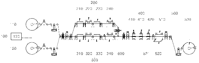
plastic molding
result in waste of valuable resources.
[10] In addition, manufacturing by molding also leads to increased volume of
the diagnosis
kits, which in turn require higher logistic cost for transportation.
[11] As a prior reference related to the present invention, the Korean Patent
Application
Publication No. 10-2012-0086985(published on Aug. 06, 2012) discloses a
technology
related to a method for manufacturing a diagnosis kit.
DETAILED DESCRIPTION OF THE INVENTION
TECHNICAL OBJECTIONS
[12] An aspect of the present invention is to provide an apparatus for
manufacturing a
diagnosis kit, in a large quantity, which can mold light-weight sheet or film
containing a
diagnostic strip inside of the sheet of film, and a diagnosis kit manufactured
therewith.
[13] Another aspect of the present invention is to provide an apparatus for
manufacturing a
diagnosis kit which can reduce the weight of the diagnosis kit and a diagnosis
kit
manufactured thereby.
[14] Still another aspect of the present invention is to provide an apparatus
for
manufacturing a diagnosis kit, the apparatus can reduce the cost of
manufacturing the
diagnosis kit, facilitate design diversification, reduce the time period
required for the
development and preparation for mass production and cost of such development,
and a
diagnosis kit manufactured thereby.
- 2 -
CA 02924150 2016-03-11
MEANS FOR ACHIEVING THE TECHNICAL OBJECTION
[15] In a preferable embodiment, the present invention provides an apparatus
for
manufacturing a diagnosis kit, comprising; a molding material feeding unit; an
upper molding
unit for receiving the upper molding material from the molding material
feeding unit and
molding it into an upper diagnosis kit body in a predetermined shape; a lower
molding unit
for receiving the lower molding material from the molding material feeding
unit and molding
it into a lower diagnosis kit body in a predetermined shape, and inserting a
diagnostic strip in
the lower diagnosis kit body; a bonding unit which receives the upper molding
material
molded in the upper molding unit and the lower molding material molded in the
lower
molding unit, and bonds the molded upper molding material and lower molding
material in
order to combine the upper diagnosis kit body and the lower diagnosis kit
body; and a
cutting unit for cutting the combined upper diagnosis kit body and the lower
diagnosis kit
body into a predetermined size of diagnosis kit.
[16] The upper molding material and the lower molding material are preferable
in the form of
a sheet of film.
[17] The upper molding unit is preferably comprised of an upper heating device
for heating
the upper molding material delivered from the upper material feeder, an upper
press
molding device for press molding the heated upper molding material into a
predetermined
shape of an upper diagnosis kit body, an upper cooling device for cooling down
the press-
molded upper molding material, and a punching device for forming a plurality
of air holes in
the diagnosis kit body included in the upper molding material.
[18] The upper diagnosis kit body comprises an upper air tube protruding
upwards in a
rectangular circumference shape, a circular tube protruding upwards in a
circular shape
placed inside of the upper air tube, a test reagent injection hole formed
inside of the circular
tube, and a plurality of air holes formed inside of the air tube, with a
certain distance from
the circular tube.
[19] The upper press molding device preferably press molds the upper air tube
and the
circular tube, and the punching device preferable punches the test reagent
injection hole
and the plurality of air holes at the same time.
- 3 -
CA 02924150 2016-03-11
[20] The lower molding unit is preferably comprised of a lower heating device
for heating the
lower molding material delivered from the molding material feeder, a lower
press molding
device for press molding the heated upper molding material into a
predetermined shape of a
lower diagnosis kit body, a lower cooling device for cooling down the press-
molded lower
molding material, and a diagnostic strip inserting device for inserting a
diagnostic strip in the
lower diagnosis kit body.
[21] The lower diagnosis kit body comprises a lower air tube having a size
corresponding
with that of the upper air tube, and a recessed hole formed inside of the air
tube by a
predetermined depth for seating the diagnostic strip.
[22] The lower press molding device preferably press-molds the lower air tube
and the
recess.
[23] In a configuration where the upper diagnosis kit body and the lower
diagnosis kit body
are formed in plurality,
[24] The diagnostic strip inserting device preferably inserts a plurality of
the diagnostic strips
delivered in a row in the recessed holes formed in the lower diagnosis kit
body sequentially
or at the same time.
[25] The bonding unit preferably heats and bonds the upper molded member and
the lower
molded member.
[26] It is preferable that, with the bottom of the upper diagnosis kit body
excluding the upper
air tube and the circular tube contacting the upside of the lower diagnosis
kit body excluding
the lower air tube and the recess, both the two diagnosis kit bodies are
heated to be fusion-
bonded to form a body of the diagnosis kit.
[27] The cutting unit preferable comprises: a cutting device for cutting out
the diagnosis kit
body from the fusion-bonded upper and lower molded members; a discharge device
provided under the cutting device for dropping and discharging out the cut
diagnosis kit body;
and a collecting device for collecting the upper and lower molded member from
which the
diagnosis kit body is cut out.
- 4 -
CA 02924150 2016-03-11
=
[28] In a different embodiment, the present invention provides a diagnosis kit
manufactured
using the apparatus for manufacturing a diagnosis kit in accordance with the
present
invention.
Effect of the Invention
[29] The present invention can manufacture diagnosis kits, in large
quantities, by press-
molding sheet or film containing diagnostic strips inside of the sheet of
film.
[30] In addition, the present invention can efficiently prevent deformation of
kit itself by
comprising a separate air tube on the diNnosis kit comprising a sheet or film
material.
[31] In addition, the present invention can reduce the weight of the diagnosis
kits.
Brief Description of the Drawings
[32] FIG. 1 shows an overall configuration in accordance with an embodiment of
the present
invention.
[33] FIG. 2 is a view of the upper heating device in accordance with an
embodiment of the
present invention.
[34] FIG. 3 is a perspective view of the upper diagnosis kit body in
accordance with an
embodiment of the present invention.
[35] FIG. 4 is a top view of the upper diagnosis kit body in accordance with
an embodiment
of the present invention.
[36] FIG. 5 is a cross-sectional view of FIG. 4 cut along the line A-A.
[37] FIG. 6 is a view of the upper press molding device in accordance with an
embodiment
of the present invention.
- 5 -
CA 02924150 2016-03-11
[38] FIG. 7 is a perspective view of the lower diagnosis kit body in
accordance with an
embodiment of the present invention.
[39] FIG. 8 is a view of the lower press molding device in accordance with an
embodiment of
the present invention.
[40] FIG. 9 is a cross-sectional view of FIG. 8 cut along the line B-B.
[41] FIG. 10 is a view of the lower press molding device in accordance with an
embodiment
of the present invention.
[42] FIG. 11 is a view of the diagnostic strip inserting device by a finger
insertion type.
[43] FIG. 12 is a view of the diagnostic strip inserting device by a vacuum
gripper type,
[44] FIG. 13 is a view of the diagnosis kit in accordance with an embodiment
of the present
invention, and
[45] FIG. 14 is a cross-sectional view of the diagnosis kit of FIG. 13.
The Best Mode for the Practice of the Invention
[46] The manufacturing apparatus for diagnosis kit of the present invention is
described
below referring to the accompanying drawings.
, [47] FIG. 1 shows an overall configuration in accordance with an embodiment
of the present
invention.
[48] Referring to FIG. 1, the apparatus for manufacturing diagnosis kits in
accordance with
an embodiment of the present invention comprises a molding material feeding
unit, an upper
molding unit, a lower molding unit, a bonding unit, and a cutting unit.
[49]
- 6 -
CA 02924150 2016-03-11
[50] Molding Material Feeding Unit (100)
[51] In this description, the upper molding material (1) and the lower molding
material (2) are
supplied in a roll as a typical embodiment.
[52] In addition, it will be obvious that the upper molding material (1) and
the lower molding
material (2) can also be supplied in a flat plate or slat form.
[53] The molding material feeding unit (100) may comprise a first feed roll
(11), a second
feed roll (120), and a rotating device (130) e.g., an electric motor for
driving the first and
second feed rolls (110, 120).
[54] The upper molding material (1) is wound on the first feed roll (110) and
the lower
molding material (2) is wound on the second feed roll (12).
[55] Here, the upper molding material (1) and lower molding material (2) are
formed in a
sheet or film shape.
[56] The upper and lower molding materials (1) and (2) can be any one of PA,
APET,
COPET, PET, PE, ABS, PS, PP, CPR, EG, PVC, PC, EVA, LDPE, and EVOH or a
combination thereof.
[57] In addition, the upper and lower molding materials (1) and (2) can be any
material which
can be heated and press molded.
[58] A first feed path is provided for the upper molding material (1) between
the first feed roll
(110) and upper molding unit (200).
[59] A second feed path is provided for the lower molding material (2) between
the second
feed roll (120) and lower molding unit (300).
[60] A plurality of dancer rolls (D) are installed in the first feed path and
the second feed path.
The dancer rolls (D) apply appropriate tension to the upper and lower molding
materials (1)
and (2) to ensure stable moving along the first feed path and the second feed
path.
- 7 -
CA 02924150 2016-03-11
[61] Meanwhile, the upper molding material (1) and lower molding material (2)
may be
applied with an additional window forming process (not shown in the drawings)
before they
are wound on the first and second feed rolls (110) and (120).
[62] The window is formed with a transparent material. The entire upper
molding material (1)
and lower molding material (2) can be formed with a transparent material or
only a portion of
the materials are provided with windows made of a transparent material.
[63]
[64] Upper Molding Unit (200)
[65] The upper molding unit (200) comprises an upper heating device (210), and
upper
press molding device (220), an upper cooling device (230), and a punching
device (240).
[66] The upper molding unit (200) provides a first molding path in connection
with the first
feed path.
[67] In addition, the upper heating device (210), upper press molding device
(220), upper
cooling device (230), and punching device (240) are arranged along in the
first molding path
in said order.
[68] FIG. 2 is a view of the upper heating device in accordance with an
embodiment of the
present invention.
[69] Referring to FIG. 2, the upper heating device (210) comprises a heating
block (211)
provided with a gap (G) through which the upper molding material (1) passes.
[70] The heating block (211) is provided with a heater device (not shown)
connected to an
outside power source.
[71] As such, the upper molding material (1) is heated by the heater device up
to a
predetermined temperature passing through the gap (G) of the heating block
(211).
[72] By the heating, the upper molding material (1) is changed to a press-
moldable state.
- 8 -
CA 02924150 2016-03-11
[73] In the present invention, the heating method can be a high frequency
induction heating,
radiative heating, or hot air heating.
[74] FIG. 2 is a view of the upper heating device in accordance with an
embodiment, of the
present invention, FIG. 3 is a perspective view of the upper diagnosis kit
body in accordance
with an embodiment of the present invention, FIG. 4 is a top view of the upper
diagnosis kit
body in accordance with an embodiment of the present invention, FIG. 5 is a
cross-sectional
view of FIG. 4 cut along the line A-A, and FIG. 6 is a view of the upper press
molding device
in accordance with an embodiment of the present invention.
[75]Next to the upper heating device (210) is an upper press molding device
(220).
[76] The upper press molding device (220) can be a press molding unit.
[77] Referring to FIGs. 3 to 5, the configuration of the upper diagnosis kit
body (10) in
accordance with an embodiment of the present invention is described.
[78] The upper diagnosis kit body (10) comprises: an upper body (11) formed
with the upper
molding material (1), un upper air tube (12) forming a rectangular
circumference protruding
upwards on the upper body (11), and a circular tube provided inside wall of
the upper air
tube (12).
[79] In addition, a test reagent injection through-hole (14) is formed inside
of the circular
tube, and a plurality of air holes (15) are formed inside of the upper air
tube (12) at a certain
distance from the circular tube.
[80] Referring to above described configuration, the upper press molding
device (220) can
comprise an upper mold (221) and a lower mold (222),and the upper molding
material (1) is
pressed and molded between the upper mold (221) and lower mold (222).
[81] For example, referring to FIG. 6, the upper mold (221) is formed with the
engraved
patterns corresponding with the shapes of the upper air tube (12) and circular
tube (13), and
the lower mold (222) is formed with embossed patterns corresponding with the
shapes of
the upper air tube (12) and circular tube (13).
- 9 -
CA 02924150 2016-03-11
[82] Accordingly, the upper molding material (1) is placed between the upper
mold (221) and
lower mold (222), and the upper mold (221) and lower mold (222) are pressed
together to
press-mold the upper molding material (1).
[83] In addition, the test reagent injection hole (14) and punch holes(15) are
formed with a
separate punching device (240).
[84] Here, any one or both of the upper mold (221) and lower mold (222) are
provided with
additional heating members (not shown), and any one or both of the upper mold
(221) and
lower mold (222) heated up by the heating members.
[85] The upper cooling device (230) cools down the upper molding material (1)
which is
transferred after being formed with the upper air tube (12) and circular tube
(13) by press
molding described above, to a predetermined temperature level.
[86] The cooling method can be water cooling or air cooling.
[87] If an air cooling device is used, it is preferable to blow low cooling
air on one side of the
upper molding material (1) at a uniform pressure.
[88] The punching device (240) is provided with a puncher (not shown) which
moves up and
down to punch holes.
[89] Here, a plurality of punchers are provided to form test reagent injection
hole (14) and air
holes (15).
[90] After cooling, the upper molding material (1) is fed into and placed at a
predetermined
position in the punching device (240).
[91] The punch heads moves up and down to punch the test reagent injection
hole (14) and
air holes (15) in the upper molding material (1) placed at the predetermined
position.
[92] It should be noted that, the punching device (240) is separated from the
upper cooling
device (230) by a predetermined distance. The spacing allows the upper molding
material (1)
to be cooled down close to the room temperature so that the rims of the punch
holes are not
damaged.
- 10 -
CA 02924150 2016-03-11
[93] Passing through the punching device (240), the upper molding material (1)
is
transferred to the arranging unit (600).
[94] The method of preheating for heat forming can make use of hot air blow, a
heating
block, or a heating roll.
[95]
[96] Lower Molding Unit (300)
[97] The lower molding unit (300) comprises a lower heating device (310), a
lower press
molding device (320), a lower cooling device (330), and a diagnostic strip
inserting device
(340).
[98] The lower molding unit (300) provides a second molding path in connection
with the
second feed path.
[99] In addition, the lower heating device (310), lower press molding device
(320), lower
cooling device (330), and diagnostic strip inserting device (340) are arranged
along in the
second molding path in said order.
[100] The lower heating device (310) comprises a heating block (311) provided
with a gap
(G) through which the lower molding material (2) passes.
[101] The heating block (311) is provided with a heating member connected to
an outside
power source.
[102] As such, the lower molding material (2) is heated by the heating member
up to a
predetermined temperature passing through the gap (G) of the heating block
(311).
[103] By the heating, the lower molding material (2) is changed to a press-
moldable state.
[104] In the present invention, the heating method can be a high frequency
induction heating,
radiative heating, or hot air heating.
[105] FIG. 7 is a perspective view of the lower diagnosis kit body in
accordance with an
embodiment of the present invention, FIG. 8 is a top view of the lower molding
device in
- 11 -
CA 02924150 2016-03-11
accordance with an embodiment of the present invention, FIG. 9 is a cross-
sectional view of
FIG. 8 cut along the line B-B, and FIG. 10 is a view of the lower press
molding device in
accordance with an embodiment of the present invention,
[106] Next to the lower heating device (310) is a lower press molding device
(320).
[107] The lower press molding device (320) can be a press molding unit.
[108] The configuration of a lower diagnosis kit body (20) in accordance with
an embodiment
of the present invention is described below.
[109] The lower diagnosis kit body (20) comprises: a lower body (21) formed
with the lower
molding material (2), a lower body (20) convex downwards forming a rectangular
circumference on the lower body (21), and a recessed hole (23) formed by a
certain depth
inside of the lower air tube (22).
[110] Referring to above described configuration, the lower press molding
device (320) can
comprise an upper mold (321) and a lower mold (322),and the lower molding
material (2) is
pressed and molded between the upper mold (321) and lower mold (322).
[111] For example, referring to FIGs. 7 to 9, the upper mold (321) is formed
with embossed
patterns corresponding with the shapes of the lower air tube (22) and recessed
hole (23),
and the lower mold is formed with engraved patterns corresponding with the
shapes of the
lower air tube (22) and recessed hole (23).
[112] Accordingly, the lower molding material (2) is placed between the upper
mold (321)
and lower mold (322), and the upper mold (321) and lower mold (322) are
pressed together
to press-mold the lower molding material (2).
[113] Here, the upper molding material (1) and lower molding material (2) can
be formed
with a plurality of upper diagnosis kit bodies (10) and lower diagnosis kit
bodies (20) at a
certain intervals.
[114] Here, any one or both of the upper mold (221) and lower mold (222) are
provided with
additional heating members (not shown), and any one or both of the upper mold
(221) and
lower mold (222) heated up by the heating members.
- 12 -
CA 02924150 2016-03-11
[115] In addition, while the present embodiment in accordance with the present
invention is
described as a press molding comprising an upper mold and a lower mold, it
would be
obvious for those skilled in the art that a roll press method can achieve the
same
performance.
[116] Furthermore, the method can also be a heat molding, vacuum molding, or
pressure
forming.
[117] The lower cooling device (330) cools down the lower molding material (2)
which is
transferred after being press-formed with the lower air tube (22) and recessed
hole (23)
described above, to a predetermined temperature level.
[118] The cooling method can be water cooling or air cooling.
[119] If an air cooling device is used, it is preferable to blow low cooling
air on one side of
the upper molding material (1) at a uniform pressure.
[120] The diagnostic strip inserting device (340) inserts a diagnostic strip
(30) in the
recessed hole (23) formed in the lower diagnosis kit body (20) which has been
cooled down.
[121]
[122] Diverse exemplary methods of inserting diagnostic strips in accordance
with the
present invention are described by referring to FIGs. 11 and 12.
[123] FIG. 11 is a view of the diagnostic strip inserting device by a finger
insertion type.
[124] Referring to FIG. 11, the diagnostic strip inserting device (340)
comprises: a strip
loading device (342) which sequentially feeds diagnostic strips (30) to the
base (341) and
the feeding position formed on the base (341); and a motored swivel finger
(343) which is
provided on the lateral side of the feeding position and pushes the diagnostic
strips (30)
placed in the feeding position into the recessed hole (23).
[125] Here, the base (341) is preferably positioned at a higher level than the
second forming
path.
- 13 -
CA 02924150 2016-03-11
[126] Accordingly, when the press molded and cooled lower molding material (2)
is
transferred to the underside of the base (341), the swivel finger (343)
rotates and pushes
the diagnostic strip (30) placed at the feeding position into the recessed
hole (22).
[127] FIG. 12 is a view of a vacuum gripper type diagnostic strip inserting
device.
[128] Referring to FIG. 12, the diagnostic strip inserting device (350)
comprises: a suction
plate (351) having suction members (351a) for gripping a plurality of the
diagnostic trips
(30); a displacing device (352) for displacing the suction plate (351); and a
vacuum
controller (353) for generating vacuum pressure and controlling gripping.
[129] Here, the spacing between the suction members (351a) shall be
substantially the
same as the spacing between the recessed holes (23) formed on the lower
molding material
(2).
[130] Accordingly, when the press-molded and cooled lower molding material (2)
is
transferred to the underside of the base (341), the suction plate (351) moves
to the upside
of the lower molding material (2) by the displacing device.
[131] Here, the positions of the recessed holes (23) formed on the lower
molding material (2)
and the suction members (351a) are the same. The suction members (351a) are
gripping
the diagnosis kits by vacuum pressure.
[132] The suction plate (351) is lowered by the displacing device (352) so
that the diagnostic
strips (30) are seated in the recessed holes (23), and the vacuum controller
releases the
vacuum pressure applied to the suction members (351a).
[133] Accordingly, the vacuum strips (30) can be seated in the recessed holes
(23).
[134] While the method of inserting the diagnostic strips (30) was described
above
according to a typical method, any other methods which can seat the diagnostic
strips (30)
in the recessed holes (23) are applicable.
[135] As described above, the lower molded material (2) seated with the
diagnostic strips
(30) is transferred to the arranging unit (600).
- 14 -
CA 02924150 2016-03-11
[136] The preheating can be achieved by uisng hot air blow, a heating block,
or a heating
roll.
[137] In an exemplary embodiment of the present invention described here, the
upper
molding material and the lower molding material are press molded, however, the
upper
molding material and the lower molding material can also be vacuum molded.
[138] That is, while not depicted in the drawings, by contacting a body formed
with desired
patterns to the upper or lower surface of the preheated and moldable upper
molding
material and applying vacuum pressure to the desired patterns using an
external vacuum
suction device, the upper molding material can be vacuum molded in a desired
shape.
[139] In addition, the lower molding material can also be molded with the same
vacuum
molding method as the upper molding material.
[140]
[141] Arranging Unit (600)
[142] The arranging unit (600) in accordance with an embodiment of the present
invention
arranges the upper and lower molded materials (1) and (2) moving along the
first and
second molding paths, respectively, can be matched at a predetermined
positions.
[143] That is, it is preferable that the arrangement state shall be so that
the upper air tube
(12) formed on the upper molding material (1) and the lower air tube (22)
formed on the
lower molding material (2) are facing each other.
[144]
[145] Bonding Unit (400)
[146] Referring to FIG. 1, the bonding unit (400) in accordance with an
embodiment of the
present invention fusion-bonds the upper and lower molding materials (1) and
(2) having
passed the arranging unit (600) and contacting each other.
[147] The bonding unit (400) provides a bonding path through which the
contacting upper
and lower molding materials (1) and (2) pass.
- 15 -
CA 02924150 2016-03-11
=
[148] The bonding unit (400) comprises one or more heat bonding devices (410)
and a
cooling device which are arranged on the bonding path sequentially.
[149] The one or more heat bonding devices (410) fusion-bonds the contacting
surfaces of
the upper and lower molding materials (1) and (2), sequentilly, excluding the
upper and
lower air tubes (12) and (22).
[150] The one or more heat bonding devices (410) can be ultrasonic welding
devices, and
their operation can be integrated into one step according to the dimension of
the diagnosis
kit to be manufactured.
[151] In addition, the bonded material (1') can be bonded by ultrasonic
fusion.
[152] The cooling device (420) cools down the bonded upper and lower molding
members
(hereinafter, "bonded material").
[153] Here, the bonded material (1') is formed with a plurality of diagnosis
kits.
[154] Then, the cooled bonded material (1') is transferred to the cuting unit
(500).
[155] In an embodiment of the present invention, the heat bonding device can
use any one
of heat fusion, high frequency induction fusion, and ultrasonic fusion.
[156]
[157] Cutting Unit (500)
[158] The cutting unit (500) cuts out the diagnosis kits from the bonding unit
(400).
[159] The cutting unit (500) is provided with a cutting device (510) having
cutter knives (not
shown) arranged corresponding with the circumference of the diagnosis kit, and
cuts the
circumference by moving up and down.
[160] In addition, if the bonded material (1') is formed with a plurality of
diagnosis kits at a
certain intervals, the cutting unit (500) may be provided with the cutter
knives whose number
corresponds with the number of the diagnosis kits.
- 16 -
CA 02924150 2016-03-11
[161] Accordingly, a plurality of the diagnosis kits can be cut off at once by
the cutter knives
moving up and down.
[162] The cutting unit (500) is provided with a discharge device (520) under
the cutting
device (510) for dropping and discharging the cutpoff diagnosis kits.
[163] The discharge device (520) is provided under the cutting device (510)
and provided
with a guide plate (521) for guiding the falling diagnosis kits.
[164] In addition, the cutting unit (500) is provided with a collecting device
(530) for
collecting the bonded material (1') excluding the diagnosis kits (hereinafter,
"scrap").
[165] The collecting device (530) can be a collecting roller which winds and
collects the
bonded material (1') from which the diagnosis kits have been cut off.
[166] In the present invention, the scraps can be cut and provessed.
[167] The apparatus for manufacturing the diagnosis kits in accordance with an
embodiment
of the present invention is described above.
Embodiments of the Present Invention
[168] The diagnosis kit manufactured with the apparatus for manufacturing the
diagnosis kits
in accordance with an embodiment of the present invention is described in
detail below.
[169] FIG. 13 is a view of the diagnosis kit in accordance with an embodiment
of the present
invention, and FIG. 14 is a cross-sectional view of the diagnosis kit of FIG.
13.
[170] The configuration of the upper diagnosis kit body (10) and lower
diagnosis kit body (20)
will refer to FIGs. 3 and 7.
[171] Referring to FIG. 13 and 14, the diagnosis kit in accordance with an
embodiment of
the present invention comprises an upper diagnosis kit body (10) and a lower
diagnosis kit
body (20) which are fusion bonded with each other.
- 17 -
CA 02924150 2016-03-11
[172]
[173] Upper Diagnosis Kit Body
[174] The upper diagnosis kit body (10) is formed from a sheet or film
material and provided
with an upper body (11) which is a rectangular plate. It would be obvious for
those skilled in
the art that the the upper diagnosis kit body (10) can be formed in various
shapes.
[175] The upper body (11) is formed with an upper air tube (12) and a circular
tube (13).
[176] The upper air tube (12) forms a rectangular circumference on the upper
body (11) and
protrudes upward.
[177] Under the upper body (11), the upper air tube (12) is formed with a
space inside.
[178] A purpose of the upper air tube (12) is to prevent the warping of the
upper body (11).
[179] Here, on the upper body (11), a circumference having a certain width is
formed outside
of the upper air tube (12).
[180] In addition, the circular tube (13) is formed inside of the upper air
tube (12) protruding
upwards from the upper body (11).
[181]Here, the longitudinal cross sections of the the upper air tube (12) and
circular tube (13)
can be the same.
[182]The circular tube (13) also provides a support.
[183] Furthermore, a test reagent injection hole (14) which is a vertical
through-hole is
formed inside of the circular tube (13).
[184] And, a plurality of the air holes (15) are formed inside of the upper
air tube (12) at a
certain distance from the circular tube (13).
[185] The plurality of air holes (15) are rectangular holes and formed as
through-holes of the
upper body (11).
- 18 -
CA 02924150 2016-03-11
[186] Here, the formation of the upper diagnosis kit body (10) is described in
the description
of the apparatus for manufacturing, thus, not described here.
[187] In addition, the upper air tube (12) and circular tube (13) can be
formed in various
shapes.
[188]
[189] Lower Diagnosis Kit Body
[190] The lower diagnosis kit body (20) is formed from a sheet or film
material and provided
with a lower body (21) formed in a rectangular planar-shape.
[191]The lower body (21) is formed with an lower air tube (22) and a recessed
hole (23).
[192]The lower air tube (22) is formed in a rectagular circumference shape on
the
undersideof the lower body (21) protruding downwards.
[193] Here, the shape of the lower air tube (22) may be substantially the same
as that of the
upper air tube (12).
[194]The recessed hole (23) is provided with a step or steps (s) at a certain
depth on the
upper surface of the lower body (21).
[195]The size of the recessed hole (23) may be determined variably in
accordance with the
size of the diagnostic strip (30) to be seated in the recess.
[196] Here, since the description of the formation of the lower diagnosis kit
body (20) is
described in the description of the apparatus for manufacturing, thus,
omitted.
[197] In accordance with an embodiment of the present invention, the upper
diagnosis kit
body (10) and the lower diagnosis kit body (20) are contacted and bonded with
each other,
and the method of bonding is preferably heat fusion as described above.
[198] That is, because the upper and lower diagnosis kit bodies (10 and 20)
are formed from
a sheet or film material, they can be fusion bonded.
- 19 -
CA 02924150 2016-03-11
[199] Accordingly, the upper body (11) and the lower body (21) form an
integral body and
the upper and lower air tubes are formed protruding upwards and downwards,
respectively.
[200] In addition, the lower air tube (22) can be formed in various shapes.
[201] And, top of the recessed hole (23) having a certain depth and length is
covered by the
upper body (11).
[202] Here, the recessed hole (23) is seated with a diagnostic strip (30).
[203]The diagnostic strip (30) is a test material that can diagnose various
diseases.
[204] Here, ann end of the diagnostic strip (30) is exposed to the test
reagent injection hole
(14) formed in the upper body (11) while another end is exposed to the
plurality of air holes
(15).
[205] As such, an end of the diagnostic strip is smeared with the test reagent
entering
through the test reagent injection hole, and the test reagent can be easily
transferred to the
opposite end by the air penetrating into the air holes on the opposite end.
[206] The exemplary embodiments of the apparatus for manufacturing a diagnosis
kit and
the diagnosis kit manufactured thereby in accordance with the present
invention are
described above, it would be obvious that various modifications and changes
can be made
without departing from the spirit of the present invention.
[207] The present invention may be embodied in other specific forms without
departing from
the spirit or essential attributes thereof and accordingly, reference should
be made to the
appended claims rather than to the foregoing specification as indicating the
scope of the
invention
[208] Therefore, the embodiments described here shall be interpreted to be
exemplary and
not limiting the present invention. It will be understood that the appended
claims are
intended to cover all such modifications and embodiments which come within the
spirit and
scope of the present invention.
- 20 -