Note: Descriptions are shown in the official language in which they were submitted.
CA 02924306 2016-12-30
ELECTRODE CATALYST HAVING A CORE-SHELL STRUCTURE
TECHNICAL FIELD
[0001]
The present invention relates to an electrode catalyst. Also, the present
invention
relates to a composition for forming a gas diffusion electrode including the
electrode
catalyst, a gas diffusion electrode, a membrane-electrode assembly, and a fuel
cell stack.
BACKGROUND ART
[0002]
A so-called polymer electrolyte fuel cell (Polymer Electrolyte Fuel Cell:
hereinafter called "PEFC" as needed), has its operating temperature of from a
room
temperature to about 80 C. Also, since PEFC makes it possible to employ
inexpensive
general-purpose plastics, etc. for members constituting its fuel cell body, it
is possible to
realize reduction in weight. Furthermore, PEFC makes it possible to achieve
thinning of a
polymer electrolyte membrane, enabling an electric resistance to be reduced,
thereby
enabling a power loss to be reduced relatively easily. Due to PEFC having not
a few
advantages as described above, it is applicable to a fuel cell vehicle, a home
cogeneration
system, and the like.
[0003]
As an electrode catalyst for PEFC, there has been proposed an electrode
catalyst in
which a platinum (Pt) or platinum (Pt) alloy, i.e., a component for the
electrode catalyst,
1
CA 02924306 2016-03-14
is supported on a carbon serving as a support (for example, Patent Document 1,
Non-
Patent Document 1).
Conventionally, there have been disclosed that, as for an electrode catalyst
for
PEFC, if the content of chlorine contained in the electrode catalyst is 100ppm
or more, it
is not desirable as an electrode catalyst (for example, Patent Document 2);
and that this is
because if the content of chlorine contained in the electrode catalyst is
100ppm or more, it
is impossible to obtain a sufficient catalytic activity for the electrode
catalyst for fuel
cells; and corrosion of its catalyst layer will occur, thus shortening the
life of the fuel cell.
[0004]
Then, there is disclosed, as the catalyst component of the electrode catalyst,
a
powder of platinum (Pt) or platinum (Pt) alloy that contains less than 100 ppm
of chlorine
(for example, Patent Document 2).
As for the preparation of a powder of the platinum (Pt) or platinum (Pt)
alloy,
there is disclosed the following method: forming a melt which contains a low-
melting
mixture of alkali-metal nitrate, a chlorine-free platinum compound and a
chlorine-free
compound of alloying elements; heating the melt up to a reaction temperature
at which
the platinum compound and the compound of the alloying elements are thermally
decomposed to give an oxide; cooling the melt; and the melt is dissolved in
water and the
resulting oxide or mixed oxides are converted into a powder of platinum or
platinum alloy
by successive reduction.
[0005]
Incidentally, the present applicant submits, as publications where the
above-mentioned publicly-known inventions are described, the following
publications:
2
CA 02924306 2016-03-14
PRIOR ART DOCUMENT
Patent Document
[0006]
Patent Document 1: Japanese Un-examined Patent Application Publication No.
2011-3492.
Patent Document 2: Japanese Un-examined Patent Application Publication No.
2003-129102 (Japanese Patent No. 4,286,499) .
Non-Patent Document
[0007]
Non-Patent Document 1: MATSUOKA et al., "Degradation of Polymer
Electrolyte fuel cells under the existence of anion species", J. Power
Sources, 2008.05.01,
Vol.179 No.2, P.560-565.
SUMMARY OF THE INVENTION
Problem to be solved by the invention
[0008]
As mentioned above, from the viewpoint of improving the catalytic activity and
lifetime of PEFC as the electrode catalyst, it is important to reduce the
content of chlorine
contained in the catalyst.
However, from the viewpoint of seeking to simplify the manufacturing process
and reduce the manufacturing cost for the practical use of PEFC, there has
been room for
improvement in the conventional arts described above.
That is, according to the aforementioned electrode catalyst having a chlorine
content of less than 100 ppm, there has been a need to prepare the same
through a
3
CA 02924306 2016-03-14
complex process for removing chlorine as disclosed in Patent Document 2, etc.,
and
hence there has been room for improvement.
Thus, when assuming a future mass production of PEFC, it is considered that
there will be required an electrode catalyst that can demonstrate a sufficient
performance
even when having a relatively high chlorine concentration as high as more than
100 ppm,
and can be prepared without a special and complicated process for eliminating
chlorine
such that the electrode catalyst is suitable for mass production and reducing
the
manufacturing cost.
[0009]
The present invention has been made in view of such technical circumstances,
and it is an object of the present invention to provide an electrode catalyst
that can exhibit
sufficient catalytic performance even when it contains a relatively high
chlorine
concentration as high as more than 100 ppm.
Also, it is another object of the present invention to provide an electrode
catalyst
that it is suitable for mass production due to the fact that there is required
no special and
complicated process for eliminating chlorine, and is also suitable for
reducing the
manufacturing cost.
Furthermore, it is a further object of the present invention to provide a
composition for forming a gas diffusion electrode, a gas diffusion electrode,
a
membrane-electrode assembly (MEA), and a fuel cell stack that include the
aforementioned electrode catalyst.
Means to solve the problem
[0010]
The present inventors, as a result of having performed intensive studies,
found
out that it is possible to produce an electrode catalyst which still exhibits
a satisfactory
4
CA 02924306 2016-03-14
performance (a core-shell catalyst to be described later), even when
containing such a
high concentration of chlorine as high as more than 100 ppm, by reducing the
concentration of bromine (Br) species contained in the electrode catalyst as
measured by
X-ray fluorescence (XRF), and have completed the present invention.
More specifically, the present invention comprises the following technical
matters:
[0011]
That is, the present invention
(1) provides an electrode catalyst having a core-shell structure comprising:
a support;
a core part formed on said support; and
a shell part formed to cover at least a part of a surface of said core part,
wherein the concentration of bromine (Br) species is not higher than 500 ppm
when
measured by X-ray fluorescence (XRF) spectroscopy, and the concentration of
chlorine (Cl) species is not higher than 8,500 ppm when measured by X-ray
fluorescence (XRF) spectroscopy.
[0012]
Even when the concentration of chlorine (Cl) species contained in the catalyst
is
extremely high as 8,500 ppm, the electrode catalyst of the present invention
can exhibit a
sufficient catalytic activity as an electrode catalyst by controlling the
concentration of the
bromine (Br) species to 500 ppm or less. Further, the electrode catalyst is
suitable for
mass production in that it does not require a special and complex
manufacturing process
of removing chlorine, and is thus suitable for reducing the manufacturing
cost.
[0013]
In the present invention, a bromine (Br) species, refers to a chemical species
containing bromine as a constituent element. Specifically, the chemical
species
5
CA 02924306 2016-03-14
containing bromine include bromine atom (Br), bromine molecule (Br2), bromide
ion
(Br -), bromine radical (Br = ), polyatomic bromine ion and a bromine compound
(e.g. X ¨
Br where X represents a counterion).
[0014]
In the present invention, the chlorine (Cl) species refers to a chemical
species
containing chlorine as a constituent element.
Specifically, the chemical species
containing chlorine include chlorine atom (Cl), chlorine molecule (C12),
chloride ion (Cl),
chlorine radical (Cl .), polyatomic chloride ion and a chlorine compound (e.g.
X -Cl
where X represents a counterion).
[0015]
In the present invention, bromine (Br) species concentration and chlorine (Cl)
species concentration are measured by X-ray fluorescence (XRF) spectrometry. A
value
of the bromine (Br) species contained in the electrode catalyst that is
measured by X-ray
fluorescence (XRF) spectrometry is the concentration of bromine (Br) species.
Likewise,
A value of the chlorine (Cl) species contained in the electrode catalyst that
is measured by
X-ray fluorescence (XRF) spectrometry is the concentration of chlorine (Cl)
species.
[0016]
Here, the bromine (Br) species concentration and chlorine (CO species
concentration are concentrations of the bromine atoms and chlorine atoms in
terms of the
bromine element and chlorine element that are respectively contained in the
electrode
catalyst.
[0017]
Further, the present invention provides
(2) the electrode catalyst as set forth in (1), in which the concentration of
chlorine
(Cl) species is not lower than 900 ppm.
In this way, the effects of the present invention can be achieved more
reliably.
6
CA 02924306 2016-03-14
[0018]
Furthermore, the present invention provides
(3) the electrode catalyst as set forth in (1) or (2), in which the shell part
contains at
least one metal selected from platinum (Pt) and a platinum (Pt) alloy, and the
core
part contains at least one metal selected from the group consisting of
palladium
(Pd), a palladium (Pd) alloy, a platinum (Pt) alloy, gold (Au), nickel (Ni)
and a
nickel (Ni) alloy.
In this way, the effects of the present invention can be achieved more
reliably. Further,
by employing the abovementioned structure, there can be achieved a higher
catalytic
activity and a higher durability.
[0019]
Furthermore, the present invention provides
(4) the electrode catalyst as set forth in (3), in which the support contains
an
electrically conductive carbon, the shell part contains platinum (Pt) and the
core
part contains palladium (Pd).
In this way, the effects of the present invention can be achieved more
reliably. Further,
by employing the abovementioned structure, there can be achieved a higher
catalytic
activity and a higher durability. Furthermore, by employing the abovementioned
structure,
the electrode catalyst of the present invention, as compared to a conventional
electrode
catalyst having a structure where platinum is supported on a carbon support,
is capable of
reducing the amount of platinum contained and is thus capable of easily
reducing a raw
material cost.
[0020]
Furthermore, the present invention provides
(5) the electrode catalyst as set forth in (1) or (2), in which the shell part
has:
a first shell part formed to cover at least a part of the surface of the core
part; and
7
CA 02924306 2016-03-14
a second shell part formed to cover at least a part of a surface of the first
shell part.
In this way, the effects of the present invention can be achieved more
reliably. By
employing the abovementioned structure, the electrode catalyst of the present
invention is
capable of reducing the contained amount of a noble metal(s) such as platinum
used in the
core part, and is thus capable of easily reducing a raw material cost.
[0021]
Furthermore, the present invention provides
(6) the electrode catalyst as set forth in (5), in which the first shell part
contains
palladium (Pd), and the second shell part contains platinum (Pt).
In this way, the effects of the present invention can be achieved more
reliably. Further,
by employing the abovementioned structure, there can be achieved a higher
catalytic
activity and a higher durability.
[0022]
Furthermore, the present invention provides
(7) a composition for forming a gas diffusion electrode, containing the
electrode
catalyst as set forth in any one of (1 ) to (6).
According to the gas diffusion electrode-forming composition of the present
invention,
it is possible to easily produce a gas diffusion electrode with a high
catalytic activity
(polarization property) because it contains the electrode catalyst of the
present invention.
[0023]
Furthermore, the present invention provides
(8) a gas diffusion electrode containing the electrode catalyst as set forth
in any
one of (1) to (6).
According to the gas diffusion electrode of the present invention, it is
possible to
__ achieve a high catalytic activity (polarization property) because it
contains the electrode
catalyst of the present invention.
8
CA 02924306 2016-03-14
[0024]
Furthermore, the present invention provides
(9) a membrane-electrode assembly (MEA) including the gas diffusion electrode
as set forth in (8).
According to the membrane-electrode assembly (MEA) of the present invention,
it is
possible to achieve a high battery property because it contains the gas
diffusion electrode
of the present invention.
[0025]
Furthermore, the present invention provides
(10) a fuel cell stack including the membrane-electrode assembly (MEA) as set
forth in (9).
According to the fuel cell stack of the present invention, it is possible to
achieve a
high battery property because it contains the membrane-electrode assembly
(MEA) of the
present invention.
Effects of the invention
[0026]
According to the present invention, there can be provided an electrode
catalyst
that can exhibit a sufficient catalytic performance even when containing a
relatively high
concentration of chlorine as high as more than 100ppm,
Also, according to the present invention, there can be provided an electrode
catalyst that is suitable for mass production due to not getting through the
particular,
complicated process for removal of chlorine and is also suitable for reduction
of the
manufacturing cost.
Further, according to the present invention, there can be provided a
composition
for forming a gas diffusion electrode, a gas diffusion electrode, a membrane-
electrode
assembly (MEA), and a fuel cell stack that include the aforementioned
electrode catalyst.
9
CA 02924306 2016-12-30
BRIEF DESCRIPTION OF THE DRAWINGS
[0027]
FIG.1 is a schematic sectional view showing a preferred embodiment of the
electrode catalyst of the present invention (core-shell catalyst).
FIG.2 is a schematic sectional view showing another preferred embodiment of
the
electrode catalyst of the present invention (core-shell catalyst).
FIG.3 is a schematic sectional view showing another preferred embodiment of
the
electrode catalyst of the present invention (core-shell catalyst).
FIG.4 is a schematic sectional view showing another preferred embodiment of
the
electrode catalyst of the present invention (core-shell catalyst).
FIG.5A is a schematic diagram showing a preferred embodiment of a fuel cell
stack of the present invention; FIG.5B is a close-up of a region of FIG.5A.
FIG.6 is a schematic diagram showing a schematic configuration of a rotating
disk
electrode measuring device equipped with a rotating disc electrode used in a
working
example.
MODE FOR CARRYING OUT THE INVENTION
[0028]
Preferable embodiments of the present invention are described in detail
hereunder
with reference to the drawings when necessary.
<Electrode catalyst>
FIG.1 is a schematic cross-sectional view showing a preferable embodiment of
an
electrode catalyst (core-shell catalyst) of the present invention.
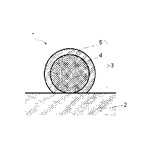
As shown in FIG.1, an electrode catalyst 1 of the present invention includes a
support 2;
and catalyst particles 3 supported on the support 2 and having a so-called
"core-shell
CA 02924306 2016-03-14
structure." Each catalyst particle 3 has a core part 4; and a shell part 5
covering at least a
part of the surface of the core part 4. The catalyst particles 3 thus have a
so-called
"core-shell structure" including the core part 4 and the shell part 5 formed
on the core part
4.
That is, the electrode catalyst 1 has the catalyst particles 3 supported on
the
support 2, and the catalyst particles 3 have the structure where the core part
4 serves as a
core (core portion), and the shell part 5 as a shell covers at least a part of
the surface of
the core part 4.
Further, the constituent element (chemical composition) of the core part 4 and
the constituent element (chemical composition) of the shell part 5 differ from
each other
in composition.
[0029]
There are no particular restrictions on the electrode catalyst 1 of the
present
invention except that the shell part 5 has to be formed on at least a part of
the surface of
the core part 4 of each catalyst particle 3.
For example, in terms of more reliably achieving the effects of the present
invention, it is preferred that the electrode catalyst 1 be in a state where
the whole range
of the surface of the core part 4 is substantially covered by the shell part
5, as shown in
FIG.1.
Further, the electrode catalyst 1 may also be in a state where a part of the
surface
of the core part 4 is covered by the shell part 5, and the rest part of the
surface of the core
part 4 is thus partially exposed, provided that the effects of the present
invention can be
achieved.
That is, with regard to the electrode catalyst of the present invention, it is
sufficient that the shell part be formed on at least a part of the surface of
the core part.
11
CA 02924306 2016-03-14
[0030]
FIG.2 is a schematic cross-sectional view showing another preferable
embodiment (electrode catalyst 1A) of the electrode catalyst (core-shell
catalyst) of the
present invention.
As shown in FIG.2, an electrode catalyst 1A of the present invention has
catalyst
particles 3a each being composed of a core part 4; a shell part 5a covering a
part of the
surface of the core part 4; and a shell part 5b covering another part of the
surface of the
core part 4.
With regard to the catalyst particles 3a contained in the electrode catalyst
1A
.. shown in FIG.2, there is a part of the core part 4 that is neither covered
by the shell part
5a nor covered by the shell part 5b. This part of the core part 4 composes a
core
part-exposed surface 4s.
That is, as shown in FIG.2, the catalyst particles 3a contained in the
electrode
catalyst 1 A may also be in a state where the surface of the core part 4 is
partially exposed
(e.g. a state where 4s as a part of the surface of the core part 4 shown in
FIG.2 is
exposed).
In other words, as is the case with the electrode catalyst 1A shown in FIG.2,
the
shell part 5a may be partially formed on a part of the surface of the core
part 4, and the
shell part 5b may then be partially formed on another part of the surface of
the core part
4.
[0031]
FIG.3 is a schematic cross-sectional view showing another preferable
embodiment (electrode catalyst 1B) of the electrode catalyst (core-shell
catalyst) of the
present invention.
12
CA 02924306 2016-03-14
As shown in FIG.3, an electrode catalyst 1B of the present invention has
catalyst
particles 3 each being composed of a core part 4; and a shell part 5
substantially covering
the whole range of the surface of the core part 4.
The shell part 5 may have a two-layered structure composed of a first shell
part 6
and a second shell part 7. That is, the catalyst particles 3 have a so-called
"core-shell
structure" comprised of the core part 4; and the shell part 5 (first shell
part 6 and second
shell part 7) formed on the core part 4.
The electrode catalyst 1B has a structure where the catalyst particles 3 are
supported on the support 2; the core part 4 of each catalyst particle 3 serves
as a core
(core portion); and the whole range of the surface of the core part 4 is
substantially
covered by the shell part 5 composed of the first shell part 6 and the second
shell part 7.
Here, the constituent element (chemical composition) of the core part 4, the
constituent element (chemical composition) of the first shell part 6 and the
constituent
element (chemical composition) of the second shell part 7 differ from one
another in
composition.
Moreover, the shell part 5 included in the electrode catalyst 1B of the
present
invention may further include another shell part in addition to the first
shell part 6 and the
second shell part 7.
In terms of more reliably achieving the effects of the present invention, it
is
preferred that the electrode catalyst 1B be in a state where the whole range
of the surface
of the core part 4 is substantially covered by the shell part 5, as shown in
FIG.3.
[0032]
FIG.4 is a schematic cross-sectional view showing another preferable
embodiment (electrode catalyst 1C) of the electrode catalyst (core-shell
catalyst) of the
present invention.
13
CA 02924306 2016-03-14
As shown in FIG.4, an electrode catalyst IC of the present invention has
catalyst
particles 3a each being composed of a core part 4; a shell part 5a covering a
part of the
surface of the core part 4; and a shell part 5b covering another part of the
surface of the
core part 4.
The shell part 5a may have a two-layered structure composed of a first shell
part
6a and a second shell part 7a.
Further, the shell part 5b may have a two-layered structure composed of a
first shell part
6b and a second shell part 7b.
That is, the catalyst particles 3a have a so-called "core-shell structure"
comprised
of the core part 4; the shell part 5a (first shell part 6a and second shell
part 7a) formed on
the core part 4; and the shell part 5b (first shell part 6b and second shell
part 7b) formed
on the core part 4.
With regard to the shell part 5b composing the catalyst particle 3a shown in
FIG.4, there is a part of the first shell part 6b that is not covered by the
second shell part
7b. The part of the first shell part 6b that is not covered by the second
shell part 7b
composes a first shell part-exposed surface 6s.
With regard to the shell part 5a composing the catalyst particle 3 shown in
FIG.4,
it is preferred that the whole range of the first shell part 6a be
substantially covered by the
second shell part 7a.
Further, as shown in FIG.4 and with regard to the shell part 5b composing each
catalyst particle 3a, also permissible is a state where a part of the surface
of the first shell
part 6b is covered, and the surface of the first shell part 6b is thus
partially exposed (e.g. a
state shown in FIG.4 where the part 6s of the surface of the first shell part
6b is exposed),
provided that the effects of the present invention can be achieved.
14
CA 02924306 2016-03-14
[0033]
Moreover, on the premise that the effects of the present invention can be
achieved, the electrode catalyst 1 may allow a "complex of the core part 4 and
shell part 5
with the whole range of the surface of the core part 4 being substantially
covered by the
shell part 5" and a "complex of the core part 4 and shell part 5 with the
surface of the core
part 4 being partially covered by the shell part 5" to coexist on the support
2 in a mixed
manner.
Specifically, the electrode catalyst of the present invention may be in a
state
where the electrode catalysts 1 and lA shown in FIGs. 1 and 2 and the
electrode catalysts
1B and 1C shown in FIGs. 3 and 4 coexist in a mixed manner, provided the
effects of the
present invention can be achieved.
Further, the electrode catalyst of the present invention may allow the shell
part
5a and the shell part 5b to coexist in a mixed manner with respect to an
identical core part
4, as shown in FIG.4, provided that the effects of the present invention can
be achieved.
Furthermore, on the premise that the effects of the present invention can be
achieved, the electrode catalyst of the present invention may allow only the
shell part 5a
to exist with respect to an identical core part 4 or only the shell part 5b to
exist with
respect to an identical core part 4 (none of these states are shown in the
drawings).
Furthermore, on the premise that the effects of the present invention can be
achieved, the electrode catalyst 1 may also be in a state where "particles
only comprised
of the core parts 4 that are not covered by the shell parts 5" are supported
on the support 2,
in addition to at least one kind of the electrode catalysts 1, 1A, 1B and 1C
(not shown).
Furthermore, on the premise that the effects of the present invention can be
achieved, the electrode catalyst 1 may also be in a state where "particles
only composed
of the constituent element of the shell part 5" are supported on the support 2
without
CA 02924306 2016-03-14
being in contact with the core parts 4, in addition to at least one kind of
the electrode
catalysts 1, 1A, 1B and 1C (not shown).
Furthermore, on the premise that the effects of the present invention can be
achieved, the electrode catalyst 1 may also be in a state where "particles
only comprised
of the core parts 4 that are not covered by the shell parts 5" and "particles
only composed
of the constituent element of the shell part 5" are individually and
independently
supported on the support 2, in addition to at least one kind of the electrode
catalysts 1, 1A,
1B and 1C.
[0034]
It is preferred that the core part 4 have an average particle diameter of 2 to
40 nm,
more preferably 4 to 20 nm, particularly preferably 5 to 15 nm.
As for the thickness of the shell part 5 (thickness from the surface in
contact with
the core part 4 to the outer surface of the shell part 5), a preferable range
thereof is to be
appropriately determined based on the design concept(s) of the electrode
catalyst.
For example, when the amount of the metal element (e.g. platinum) used to
compose the shell part 5 is intended to be minimized, a layer composed of one
atom (one
atomic layer) is preferred. In this case, when there is only one kind of metal
element
composing the shell part 5, it is preferred that the thickness of the shell
part 5 be twice as
large as the diameter of one atom of such metal element (in spherical
approximation).
Further, when there are not fewer than two kinds of metal elements composing
the shell
part 5, it is preferred that the thickness of the shell part 5 be that of a
layer of one atom
(one atomic layer formed with two or more kinds of atoms being apposed on the
surface
of the core part 4).
Further, for example, when attempting to improve a durability by employing a
shell part 5 of a larger thickness, it is preferred that such thickness be 1
to 10 nm, more
preferably 2 to 5 nm.
16
CA 02924306 2016-03-14
[0035]
When the shell part 5 has the two-layered structure composed of the first
shell
part 6 and the second shell part 7, preferable ranges of the thicknesses of
the first shell
part 6 and second shell part 7 are appropriately determined based on the
design concept(s)
of the electrode catalyst of the present invention.
For example, when the amount of a noble metal such as platinum (Pt) as a metal
element contained in the second shell part 7 is intended to be minimized, it
is preferred
that the second shell part 7 be a layer composed of one atom (one atomic
layer). In this
case, when there is only one kind of metal element composing the second shell
part 7, it is
preferred that the thickness of the second shell part 7 be approximately twice
as large as
the diameter of one atom of such metal element (provided that an atom is
considered as a
sphere).
Further, when there are not fewer than two kinds of metal elements contained
in
the second shell part 7, it is preferred that the second shell part 7 have a
thickness
equivalent to that of a layer composed of not fewer than one kind of atom (one
atomic
layer formed with two or more kinds of atoms being apposed in the surface
direction of
the core part 4). For example, when attempting to improve the durability of
the electrode
catalyst by employing a second shell part 7 of a larger thickness, it is
preferred that the
thickness of the second shell part 7 be 1.0 to 5.0 nm. If the durability of
the electrode
catalyst is to be further improved, it is preferred that the thickness of the
second shell part
7 be 2.0 to 10.0 nm.
Here, in the present invention, "average particle diameter" refers to an
average value of
the diameters of an arbitrary number of particles as particle groups that are
observed
through electron micrographs.
17
CA 02924306 2016-12-30
[0036]
There are no particular restrictions on the support 2, as long as such support
2 is
capable of supporting the catalyst particles 3 as the complexes composed of
the core parts 4
and the shell parts 5, and has a large surface area.
Moreover, it is preferred that the support 2 be that exhibiting a favorable
dispersibility and a superior electrical conductivity in a composition used to
form a gas
diffusion electrode having the electrode catalyst 1.
[0037]
The support 2 may be appropriately selected from carbon-based materials such
as
glassy carbon (GC), fine carbon, carbon black, black lead, carbon fiber,
activated carbon,
ground product of activated carbon, carbon nanofiber and carbon nanotube; and
glass-based or ceramic-based materials such as oxides.
Among these materials, carbon-based materials are preferred in terms of their
adsorptivities with respect to the core part 4 and in terms of a BET specific
surface area of
the support 2.
Further, as a carbon-based material, an electrically conductive carbon is
preferred.
Particularly, an electrically conductive carbon black is preferred as an
electrically
conductive carbon. Examples of such electrically conductive carbon black
include
products by the names of "KetjenblackTm EC300 J," "KetjenblackTm EC600" and
"Carbon
EPC" (produced by Lion Corporation).
[0038]
There are no particular restrictions on the component of the core part 4, as
long as
the component is capable of being covered by the shell part 5.
When the shell part 5 employs a one-layered structure as are the cases with
the
electrode catalysts 1 and 1A that are shown in FIGs. 1 and 2 instead of the
two-layered
structure, the core part 4 may also employ a noble metal(s). The core part 4
composing
18
CA 02924306 2016-03-14
the catalyst particles 3 and 3a of the electrode catalysts 1 and 1A, contains
at least one
metal selected from the group consisting of palladium (Pd), a palladium (Pd)
alloy, a
platinum (Pt) alloy, gold (Au), nickel (Ni) and a nickel (Ni) alloy.
[0039]
There are no particular restrictions on a palladium (Pd) alloy, as long as the
alloy
is to be obtained by combining palladium (Pd) with another metal capable of
forming an
alloy when combined with palladium (Pd). For example, such palladium (Pd)
alloy may
be a two-component palladium (Pd) alloy obtained by combining palladium (Pd)
with
another metal; or a three or more-component palladium (Pd) alloy obtained by
combining
palladium (Pd) with not fewer than two kinds of other metals. Specifically,
examples of
such two-component palladium (Pd) alloy include gold palladium (PdAu), silver
palladium (PdAg) and copper palladium (PdCu). One example of a three-component
palladium (Pd) alloy is gold-silver-palladium (PdAuAg).
[0040]
There are no particular restrictions on a platinum (Pt) alloy, as long as the
alloy is
to be obtained by combining platinum (Pt) with another metal capable of
forming an alloy
when combined with platinum (Pt). For example, such platinum (Pt) alloy may be
a
two-component platinum (Pt) alloy obtained by combining platinum (Pt) with
another
metal; or a three or more-component platinum (Pt) alloy obtained by combining
platinum
(Pt) with not fewer than two kinds of other metals. Specifically, examples of
such
two-component platinum (Pt) alloy include nickel platinum (PtNi) and cobalt
platinum
(PtCo).
[0041]
There are no particular restrictions on a nickel (Ni) alloy, as long as the
alloy is
to be obtained by combining nickel (Ni) with another metal capable of forming
an alloy
when combined with nickel (Ni). For example, such nickel (Ni) alloy may be a
19
CA 02924306 2016-03-14
two-component nickel (Ni) alloy obtained by combining nickel (Ni) with another
metal;
or a three or more-component nickel (Ni) alloy obtained by combining nickel
(Ni) with
not fewer than two kinds of other metals. Specifically, one example of such
two-component nickel (Ni) alloy is tungsten nickel (NiW).
[0042]
The shell part 5 contains at least one kind of metal selected from platinum
(Pt)
and a platinum (Pt) alloy. There are no particular restrictions on a platinum
(Pt) alloy, as
long as the alloy is to be obtained by combining platinum (Pt) with another
metal capable
of forming an alloy when combined with platinum (Pt). For example, such
platinum (Pt)
alloy may be a two-component platinum (Pt) alloy obtained by combining
platinum (Pt)
with another metal; or a three or more-component platinum (Pt) alloy obtained
by
combining platinum (Pt) with not fewer than two kinds of other metals.
Specifically,
examples of such two-component platinum (Pt) alloy include nickel platinum
(PtNi),
cobalt platinum (PtCo), platinum ruthenium (PtRu), platinum molybdenum (PtMo)
and
platinum titanium (PtTi). Particularly, in order for the shell part 5 to have
a poisoning
resistance, it is preferred that a platinum ruthenium (PtRu) alloy be used.
[0043]
As are the cases with the electrode catalysts 1B and 1C that are shown in
FIGs. 3
and 4, when the shell part 5 employs the two-layered structure composed of the
first shell
part 6 and the second shell part 7, a metal element(s) other than noble metals
may be the
main component especially from the perspective of reducing the cost for
producing the
electrode catalyst 1. Specifically, it is preferred that the core part 4 be
composed of a
metal element(s) other than platinum (Pt) and palladium (Pd), a metal compound
of such
metal and/or a mixture of such metal and such metal compound. It is more
preferred that
the core part 4 be composed of a metal element(s) other noble metals, a metal
compound
of such metal and/or a mixture of such metal and such metal compound.
CA 02924306 2016-03-14
[0044]
A supported amount of the platinum (Pt) contained in the shell part 5 is 5 to
30%
by weight, preferably 8 to 25% by weight with respect to the weight of the
electrode
catalyst 1. It is preferred that the amount of the platinum (Pt) supported be
not smaller
than 5% by weight, because the electrode catalyst can fully exert its
catalytic activity in
such case. It is also preferred that the amount of the platinum (Pt) supported
be not larger
than 30% by weight, because the amount of platinum (Pt) used is thus reduced
in such
case, which is favorable in terms of production cost.
[0045]
In the case where the shell part 5 has the two-layered structure composed of
the
first shell part 6 and the second shell part 7, it is preferred that the first
shell part 6 contain
at least one kind of metal selected from the group consisting of palladium
(Pd), a
palladium (Pd) alloy, a platinum (Pt) alloy, gold (Au), nickel (Ni) and a
nickel (Ni) alloy,
and it is more preferred that the first shell part 6 contain palladium (Pd)
simple substance.
From the perspective of further improving the catalytic activities of the
electrode
catalysts 1B and 1C and more easily obtaining the same, it is preferred that
the first shell
part 6 be mainly composed of palladium (Pd) simple substance (not less than 50
wt%),
and it is more preferred that such first shell part 6 be only composed of
palladium (Pd)
simple substance.
It is preferred that the second shell part 7 contain at least one kind of
metal
selected from platinum (Pt) and a platinum (Pt) alloy, and it is more
preferred that such
shell part 7 contain platinum (Pt) simple substance.
From the perspective of further improving the catalytic activities of the
electrode
catalysts 1B and 1C and more easily obtaining the same, it is preferred that
the second
shell part 7 be mainly composed of platinum (Pt) simple substance (not less
than 50 wt%),
21
CA 02924306 2016-03-14
and it is more preferred that such second shell part 7 be only composed of
platinum (Pt)
simple substance.
[0046]
(Concentration of bromine (Br) species and concentration of chlorine (Cl)
species)
The electrode catalyst 1 exhibits a bromine (Br) species concentration of not
higher than 500 ppm when measured through X-ray fluorescence (XRF)
spectroscopy;
and a chlorine (Cl) species concentration of not higher than 8,500 ppm when
measured
through the same analytical method.
[0047]
Even when the chlorine (Cl) species contained in the electrode catalyst 1 is
in an
extremely high concentration of 8,500 ppm, the electrode catalyst 1 is able to
fully exert
its catalytic activity by having a bromine (Br) species concentration of not
higher than
500 ppm. Further, the electrode catalyst 1 is suitable for mass production and
production
cost reduction due to the fact that not special and complex production process
is required
to remove chlorine.
[0048]
Here, the bromine (Br) species concentration and the chlorine (Cl) species
concentration are measured through X-ray fluorescence (XRF) spectroscopy. A
value
obtained by measuring the bromine (Br) species contained in the electrode
catalyst
through X-ray fluorescence (XRF) spectroscopy is the bromine (Br) species
concentration.
Similarly, a value obtained by measuring the chlorine (Cl) species contained
in the
electrode catalyst through X-ray fluorescence (XRF) spectroscopy is the
chlorine (Cl)
species concentration.
Here, the bromine (Br) species concentration and the chlorine (Cl) species
concentration are respectively the concentrations of the bromine atoms and
chlorine
atoms in terms of the bromine and chlorine elements contained in the electrode
catalyst.
22
CA 02924306 2016-03-14
[0049]
X-ray fluorescence (XRF) spectroscopy is a method where a specimen
containing a particular element A is irradiated with a primary X-ray to
generate a
fluorescent X-ray of such element A, followed by measuring the intensity of
such
fluorescent X-ray of the element A such that quantitative analysis of the
captioned
element A contained in the specimen can be performed. When performing
quantitative
analysis through X-ray fluorescence (XRF) spectroscopy, there may be employed
the
fundamental parameter method (FP method) used in theoretical operation.
The FP method applies the idea that if the compositions and kinds of the
elements contained in a specimen are all known, the fluorescent X-ray (XRF)
intensities
thereof can be individually and theoretically calculated. In addition, the FP
method allows
there to be estimated a composition(s) corresponding to the fluorescent X-ray
(XRF) of
each element that is obtained by measuring the specimen.
[0050]
X-ray fluorescence (XRF) spectroscopy is performed using general fluorescent
X-ray (XRF) analyzers such as an energy dispersive fluorescent X-ray (XRF)
analyzer, a
scanning-type fluorescent X-ray (XRF) analyzer and a multi-element
simultaneous-type
fluorescent X-ray (XRF) analyzer. A fluorescent X-ray (XRF) analyzer is
equipped with a
software which makes it possible to process the experimental data regarding
the
correlation between the intensity of the fluorescent X-ray (XRF) of the
element A and the
concentration of the element A.
There are no particular restrictions on such software, as long as the software
is
that generally used to perfotni X-ray fluorescence (XRF) spectroscopy.
For example, there may be employed a software for use in a general fluorescent
X-ray (XRF) analyzer adopting the FP method, such as an analysis software:
"UniQuant
5". Here, one example of the abovementioned fluorescent X-ray (XRF) analyzer
is a
23
CA 02924306 2016-03-14
full-automatic wavelength dispersive fluorescent X-ray analyzer (product name:
Axios by
Spectris Co., Ltd.)
[0051]
The electrode catalyst 1 exhibits a bromine (Br) species concentration of not
higher than 500 ppm when measured by the aforementioned X-ray fluorescence
(XRF)
spectroscopy. However, from the perspective of further reliably achieving the
effects of
the present invention, it preferred that the bromine (Br) species
concentration be not
higher than 300 ppm, more preferably not higher than 200 ppm, and particularly
preferably not higher than 100 ppm. A bromine (Br) species concentration of
not higher
than 500 ppm is preferable, because the electrode catalyst 1 is capable of
fully exerting its
catalytic activity in such case even when containing a chlorine (Cl) species
of a high
concentration.
[0052]
In order to achieve a bromine (Br) species concentration of not higher than
500
ppm when measured by the aforementioned X-ray fluorescence (XRF) spectroscopy,
it is
required that a metal compound as a staring material of the electrode catalyst
1 and a
reagent(s) used in each production step of the electrode catalyst 1 be
carefully selected.
Specifically, there may, for example, be used a metal compound that does not
generate
bromine (Br) species, as the metal compound serving as the starting material
of the
electrode catalyst 1. Further, there may, for example, be employed a
compound(s) that do
not contain bromine (Br) species, as the reagent(s) used in the production
steps of the
electrode catalyst 1.
[0053]
Moreover, while the electrode catalyst 1 exhibits a chlorine (Cl) species
concentration of not higher than 8,500 ppm when measured by the abovementioned
X-ray
fluorescence (XRF) spectroscopy, it is preferred that such chlorine (Cl)
species
24
CA 02924306 2016-03-14
concentration be not higher than 7,500 ppm, more preferably not higher than
6,500 ppm,
even more preferably not higher than 5,500 ppm, and particularly preferably
not higher
than 2,500 ppm. In addition, it is especially preferred that the chlorine (Cl)
species
concentration be 1,000 ppm when measured by such X-ray fluorescence (XRF)
.. spectroscopy.
It is preferable when the chlorine (Cl) species concentration is not higher
than
8,500 ppm, because the electrode catalyst 1 is capable of fully exerting its
catalytic
activity under such condition due to the chlorine (Cl) species. Further, it is
preferable
when the chlorine (Cl) species concentration is not higher than 8,500 ppm,
because the
electrode catalyst 1 can thus be produced without the production process of
removing the
chlorine (Cl) species, in the production process of the electrode catalyst 1.
[0054]
The electrode catalyst 1 of the present invention is capable of fully
delivering its
performance as an electrode catalyst even when the chlorine (Cl) species
concentration
measured by the abovementioned X-ray fluorescence (XRF) spectroscopy is not
lower
than 900 ppm, or even greater than 5,000 ppm.
That is, one technical feature of the electrode catalyst of the present
invention is
that bromine (Br) species is focused, and the bromine (Br) species
concentration
measured by the abovementioned X-ray fluorescence (XRF) spectroscopy is
regulated to
.. not higher than 500 ppm such that the electrode catalyst is allowed to
fully deliver its
performance even when the chlorine (Cl) species concentration measured by the
abovementioned X-ray fluorescence (XRF) spectroscopy is greater than 5,000 ppm
(not
higher than 8,500 ppm).
[0055]
In order to achieve a chlorine (Cl) species concentration of not higher than
8,500
ppm when measured by the abovementioned X-ray fluorescence (XRF) spectroscopy,
it is
CA 02924306 2016-03-14
required that a metal compound as a staring material of the electrode catalyst
1 and
reagents used in production steps of the electrode catalyst be carefully
selected.
Specifically, there may, for example, be used a metal compound that does not
generate
chlorine (Cl) species, as the metal compound serving as the starting material
of the
electrode catalyst 1. Further, there may, for example, be employed compounds
that do not
contain chlorine (Cl) species, as the reagents used in the production steps of
the electrode
catalyst 1.
Further, chlorine (Cl) species can be reduced to approximately several tens of
ppm by employing the chlorine reduction methods described later.
[0056] <Production method of electrode catalyst>
A production method of the electrode catalyst 1 includes a step of producing
an
electrode catalyst precursor; and a step of washing such catalyst precursor to
meet the
condition where the bromine (Br) species concentration measured by the X-ray
fluorescence (XRF) spectroscopy is not higher than 500 ppm, and the chlorine
(Cl)
species concentration measured by the same method is not higher than 8,500
ppm.
[0057] (Production step of electrode catalyst precursor)
The electrode catalyst precursor of the electrode catalyst 1 is produced by
having
the support 2 support the catalyst components (core part 4, shell part 5) of
the electrode
catalyst.
There are no particular restrictions on a production method of the electrode
catalyst precursor as long as the method allows the catalyst components of the
electrode
catalyst 1 to be supported on the support 2.
Examples of the production method of the electrode catalyst precursor include
an
impregnation method where a solution containing the catalyst components of the
electrode catalyst 1 is brought into contact with the support 2 to impregnate
the support 2
26
CA 02924306 2016-03-14
with the catalyst components; a liquid phase reduction method where a
reductant is put
into a solution containing the catalyst components of the electrode catalyst
1; an
electrochemical deposition method such as under-potential deposition (UPD); a
chemical
reduction method; a reductive deposition method using adsorption hydrogen; a
surface
leaching method of alloy catalyst; immersion plating; a displacement plating
method; a
sputtering method; and a vacuum evaporation method.
[0058] (Concentration of bromine (Br) species and concentration of chlorine
(Cl) species)
Next, the concentrations of the bromine (Br) species and chlorine (Cl) species
of
the electrode catalyst precursor are adjusted to meet the condition where the
bromine (Br)
species concentration measured by the X-ray fluorescence (XRF) spectroscopy is
not
higher than 500 ppm, and the chlorine (Cl) species concentration measured by
the same
method is not higher than 8,500 ppm. Specifically, there are employed the
following
chlorine reduction methods 1 to 3.
[0059] [Chlorine reduction method 1]
A chlorine reduction method 1 includes a first step and a second step.
First step: The first step is to prepare a first liquid with an electrode
catalyst
precursor (I) being dispersed in an ultrapure water. The first liquid is
prepared by adding
such electrode catalyst precursor (I) to the ultrapure water. Here, the
electrode catalyst
precursor (I) is produced using a material containing chlorine (Cl) species,
and exhibits a
chlorine (Cl) species concentration higher than a predetermined chlorine (Cl)
species
concentration when measured by the X-ray fluorescence (XRF) spectroscopy (e.g.
an
electrode catalyst precursor exhibiting a chlorine (Cl) species concentration
value higher
than 8,500 ppm or 7,600 ppm, provided that 8,500 ppm or 7,600 ppm is the
predetermined chlorine (Cl) species concentration).
Second step: The second step is to prepare a second liquid with an electrode
catalyst precursor (II) being dispersed in the ultrapure water. Specifically,
the electrode
27
CA 02924306 2016-03-14
catalyst precursor (I) contained in the first liquid is filtrated and washed
using the
ultrapure water, followed by repeatedly washing the same until a filtrate
obtained after
washing has exhibited an electric conductivity p that is not higher than a
predetermined
value when measured by a JIS-standard testing method (HS K0552) (e.g. not
higher than
a value predetermined within a range of 10 to 100 ttS/cm). In this way, there
is obtained
the electrode catalyst precursor (II) as well as the second liquid with such
electrode
catalyst precursor (II) being dispersed in the ultrapure water.
[0060] [Chlorine reduction method 2]
A chlorine reduction method 2 includes a first step, a second step, a third
step
and a fourth step.
First step: The first step is to retain a liquid containing an ultrapure
water, a
reductant and an electrode catalyst precursor under at least one temperature
predetermined within a range of 20 to 90 C for a predetermined retention time.
Here, the
electrode catalyst precursor is produced using a material containing chlorine
(Cl) species,
and exhibits a chlorine (Cl) species concentration higher than a predetermined
chlorine
(Cl) species concentration when measured by the X-ray fluorescence (XRF)
spectroscopy
(e.g. an electrode catalyst precursor exhibiting a chlorine (Cl) species
concentration value
higher than 8,500 ppm or 6,000 ppm, provided that 8,500 ppm or 6,000 ppm is
the
predetermined chlorine concentration).
Second step: The second step is to add the ultrapure water to the liquid
obtained
in the first step so as to prepare a first liquid where an electrode catalyst
precursor (I)
contained in the liquid obtained in the first step is dispersed in the
ultrapure water.
Third step: The third step is to filtrate and wash the electrode catalyst
precursor
contained in the first liquid using the ultrapure water, followed by
repeatedly washing the
same until a filtrate obtained after washing has exhibited an electric
conductivity p that is
not higher than a predetermined first value when measured by a JIS-standard
testing
28
CA 02924306 2016-03-14
method (JIS K0552). In this way, there is now obtained a second liquid where
dispersed
in the ultrapure water is the electrode catalyst precursor contained in the
liquid having an
electric conductivity p that is not higher than the predetermined first value.
Fourth step: The fourth step is to dry the second liquid.
.. [0061] [Chlorine reduction method 3]
A chlorine reduction method 3 includes a first step.
First step: The first step is to retain a liquid containing an ultrapure
water, a gas
having hydrogen and an electrode catalyst precursor under at least one
temperature
predetermined within a range of 20 to 40 C for a predetermined retention time.
Here, the
.. electrode catalyst precursor is produced using a material containing
chlorine (Cl) species,
and exhibits a chlorine (Cl) species concentration higher than a predetermined
chlorine
(Cl) species concentration when measured by the X-ray fluorescence (XRF)
spectroscopy.
[0062]
The "ultrapure water" used in the chlorine reduction methods 1 to 3 is a type
of
water exhibiting a specific resistance R of not lower than 3.0 MO.cm, such
specific
resistance R being represented by the following general formula (1) (i.e. an
inverse
number of the electric conductivity measured by the JIS-standard testing
method (JIS
K0552) ). Further, it is preferred that the "ultrapure water" have a water
quality
equivalent to or clearer than "A3" as defined in JISK 0557 "Water used for
industrial
water and wastewater analysis."
[0063] [Formula 1]
R = 1 / p ( 1 )
In the above general formula (1), R represents the specific resistance, and p
represents the electric conductivity measured by the JIS-standard testing
method (JIS
K0552).
29
CA 02924306 2016-03-14
[0064]
There are no particular restrictions on the ultrapure water, as long as the
water
has an electric conductivity that satisfies the relationship represented by
the general
formula (1). Examples of such ultrapure water include an ultrapure water
produced using
an ultrapure water system from "Milli-Q series" (by Merck Ltd.); and an
ultrapure water
produced using an ultrapure water system from "Elix UV series" (by Nihon
Millipore
K.K.).
[0065]
The chlorine (Cl) species contained in the electrode catalyst precursor can be
reduced by performing any one of the chlorine reduction methods 1 to 3.
Further, an
electrode catalyst precursor exhibiting a bromine (Br) species concentration
of not higher
than 500 ppm and a chlorine (Cl) species concentration of not higher than
8,500 ppm
when measured by the X-ray fluorescence (XRF) spectroscopy, is considered as
the
electrode catalyst of the present invention.
[0066]
The electrode catalyst is capable of exerting a level of catalytic activity
required
as an electrode catalyst, due to the fact that the electrode catalyst has a
chlorine (Cl)
species concentration of not higher than 8,500 ppm and a bromine (Br) species
concentration of not higher than 500 ppm when measured by the X-ray
fluorescence
(XRF) spectroscopy.
[0067] (X-ray fluorescence (XRF) spectroscopy)
The X-ray fluorescence (XRF) spectroscopy is, for example, performed in the
following manner.
(1) Measurement device
= Full-automatic wavelength dispersive fluorescent X-ray analyzer Axios (by
Spectris
Co., Ltd.)
CA 02924306 2016-12-30
(2) Measurement condition
.Analysis software: "UniQuant 5" (Semi-quantitative analysis software
employing FP
(four peak method))
= XRF measurement chamber atmosphere: Helium (normal pressure)
(3) Measurement procedure
(i) Placing a sample-containing sample container into an XRF sample chamber
(ii) Replacing an atmosphere in the XRF sample chamber with helium gas
(iii) Setting the measurement condition to "UQ5 application" as a condition
required to
use the analysis software "UniQuant 5" and configuring a mode where
calculation
is performed in a mode with the main component of the sample being "carbon
(constituent element of support)" and with a sample analysis result-display
format
being "element," under a helium gas atmosphere (normal pressure)
[0068] <Structure of fuel cell stack>
FIG.5A is a schematic view showing preferable embodiments of a composition for
forming gas diffusion electrode containing the electrode catalyst of the
present invention; a
gas diffusion electrode produced using such composition for forming gas
diffusion
electrode; a membrane-electrode assembly (MEA) having such gas diffusion
electrode;
and a fuel cell stack having such membrane-electrode assembly (MEA). FIG.5B is
a
close-up of a region of FIG.5A.
As for a fuel cell stack S shown in FIG.5A and FIG.5B, each membrane-electrode
assembly (MEA) 400 serves as a one-unit cell, and the fuel cell stack S is
configured by
stacking multiple layers of such one-unit cells.
[0069]
Particularly, the fuel cell stack S has a membrane-electrode assembly (MEA)
400
that is equipped with an anode 200a, a cathode 200b and an electrolyte
membrane 300
provided between these electrodes.
31
CA 02924306 2016-03-14
More particularly, the fuel cell stack S has a structure where the
membrane-electrode assembly (MEA) 400 is sandwiched between a separator 100a
and a
separator 100b.
[0070]
Described hereunder are the composition for forming gas diffusion electrode, a
gas diffusion electrode 200a, a gas diffusion electrode 200b and the membrane-
electrode
assembly (MEA) 400, all of which serve as members of the fuel cell stack S
containing
the electrode catalyst of the present invention.
[0071] <Composition for forming gas diffusion electrode>
The electrode catalyst 1 can be used as a so-called catalyst ink component and
serve as the composition for forming gas diffusion electrode in the present
invention. One
feature of the composition for forming gas diffusion electrode in the present
invention is
that this composition contains the aforementioned electrode catalyst. The main
components of the composition for forming gas diffusion electrode are the
abovementioned electrode catalyst and an ionomer solution. The ionomer
solution
contains water, an alcohol and a polyelectrolyte exhibiting a hydrogen ion
conductivity.
[0072]
A mixing ratio between water and an alcohol in the ionomer solution can be any
ratio, as long as it is the kind of ratio capable of endowing a viscosity
suitable for
applying to the electrode the composition for forming gas diffusion electrode.
In general,
it is preferred that an alcohol be contained in an amount of 0.1 to 50.0 parts
by weight
with respect to 100 parts by weight of water. Further, it is preferred that
the alcohol
contained in the ionomer solution be a monohydric alcohol or a polyhydric
alcohol.
Examples of a monohydric alcohol include methanol, ethanol, propanol and
butanol.
Examples of a polyhydric alcohol include dihydric alcohols or trihydric
alcohols. As a
dihydric alcohol, there can be listed, for example, ethylene glycol,
diethylene glycol,
32
CA 02924306 2016-03-14
tetraethylene glycol, propylene glycol, 1,3-butanediol and 1,4-butanediol. As
a trihydric
alcohol, there may be used glycerin, for example. Further, the alcohol
contained in the
ionomer solution may be either one kind of alcohol or a combination of two or
more
kinds of alcohols. Here, the ionomer solution may also be appropriately
allowed to
contain an additive(s) such as a surfactant, if necessary.
[0073]
For the purpose of dispersing the electrode catalyst, the ionomer solution
contains a hydrogen ion-conductive polyelectrolyte as a binder component for
improving
an adhesion to a gas diffusion layer as a part composing the gas diffusion
electrode.
Although there are no particular restrictions on the polyelectrolyte, examples
of such
polyelectrolyte include known perfluorocarbon resins having sulfonate groups
and/or
carboxylic acid groups. As an easily obtainable hydrogen ion-conductive
polyelectrolyte,
there can be listed, for example, Nafion (registered trademark of Du Pont),
ACIPLEX
(registered trademark of Asahi Kasei Chemical Corporation) and Flemion
(registered
trademark of ASAHI GLASS Co., Ltd).
[0074]
The composition for forming gas diffusion electrode can be produced by mixing,
crushing and stirring the electrode catalyst and the ionomer solution. The
composition for
forming gas diffusion electrode may be prepared using crushing and mixing
machines
such as a ball mill and/or an ultrasonic disperser. A crushing and a stirring
conditions at
the time of operating a crushing and mixing machine can be appropriately
determined in
accordance with the mode of the composition for forming gas diffusion
electrode.
[0075]
It is required that the composition of each of the electrode catalyst, water,
alcohol(s) and hydrogen ion-conductive polyelectrolyte that are contained in
the
composition for forming gas diffusion electrode be that capable of achieving a
favorable
33
CA 02924306 2016-03-14
dispersion state of the electrode catalyst, allowing the electrode catalyst to
be distributed
throughout an entire catalyst layer of the gas diffusion electrode and
improving the power
generation performance of the fuel cell.
[0076]
Particularly, it is preferred that the polyelectrolyte, alcohol(s) and water
be
respectively contained in an amount of 0.1 to 2.0 parts by weight, an amount
of 0.01 to
2.0 parts by weight and an amount of 2.0 to 20.0 parts by weight with respect
to 1.0 parts
by weight of the electrode catalyst. It is more preferred that the
polyelectrolyte, alcohol(s)
and water be respectively contained in an amount of 0.3 to 1.0 parts by
weight, an amount
of 0.1 to 2.0 parts by weight and an amount of 5.0 to 6.0 parts by weight with
respect to
1.0 parts by weight of the electrode catalyst. It is preferred that the
composition of each
component be within the abovementioned ranges, because when the composition of
each
component is within these ranges, not only a coating film made of the
composition for
forming gas diffusion electrode will not be spread extremely extensively on
the gas
diffusion electrode at the time of forming the film, but the coating film
formed of the
composition for forming gas diffusion electrode is also allowed to have an
appropriate
and uniform thickness.
[0077]
Here, the weight of the polyelectrolyte refers to a weight when it is dry i.e.
a
weight without a solvent in a polyelectrolyte solution, whereas the weight of
water refers
to a weight including a water contained in the polyelectrolyte solution.
[0078] <Gas diffusion electrode>
The gas diffusion electrode (200a, 200b) of the present invention has a gas
diffusion layer 220; and an electrode catalyst layer 240 laminated on at least
one surface
of the gas diffusion layer 220. The aforementioned electrode catalyst is
contained in the
34
CA 02924306 2016-12-30
electrode catalyst layer 240 equipped to the gas diffusion electrode (200a,
200b). The gas
diffusion electrode 200 of the present invention can be used as an anode and
an cathode.
In FIG.5A and FIG.5B, the gas diffusion electrode 200 on the upper side is
referred to as the anode 200a, whereas the gas diffusion electrode 200 on the
lower side is
referred to as the cathode 200b for the sake of convenience.
[0079] (Electrode catalyst layer)
In the case of the anode 200a, the electrode catalyst layer 240 serves as a
layer
where a chemical reaction of dissociating a hydrogen gas sent from the gas
diffusion layer
220 into hydrogen ions takes place due to the function of the electrode
catalyst 1 contained
in the electrode catalyst layer 240. Further, in the case of the cathode 200b,
the electrode
catalyst layer 240 serves as a layer where a chemical reaction of bonding an
air (oxygen
gas) sent from the gas diffusion layer 220 and the hydrogen ions that have
traveled from the
anode through the electrolyte membrane takes place due to the function of the
electrode
catalyst 1 contained in the electrode catalyst layer 240.
[0080]
The electrode catalyst layer 240 is formed using the abovementioned
composition
for forming gas diffusion electrode. It is preferred that the electrode
catalyst layer 240 have
a large surface area such that the reaction between the electrode catalyst 1
and the hydrogen
gas or air (oxygen gas) sent from the diffusion layer 220 is allowed take
place to the fullest
extent. Moreover, it is preferred that the electrode catalyst layer 240 be
formed in a manner
such that the electrode catalyst layer 240 has a uniform thickness as a whole.
Although the
thickness of the electrode catalyst layer 240 can be appropriately adjusted
and there are no
restrictions on such thickness, it is preferred that the electrode catalyst
layer 240 have a
thickness of 2 to 200 ktm.
CA 02924306 2016-03-14
[0081] (Gas diffusion layer)
The gas diffusion layer 220 equipped to the gas diffusion electrode 200 serves
as
a layer provided to diffuse to each of the corresponding electrode catalyst
layers 240 the
hydrogen gas introduced from outside the fuel cell stack S into gas flow
passages that are
formed between the separator 100a and the gas diffusion layer 220a; and the
air (oxygen
gas) introduced from outside the fuel cell stack S into gas passages that are
formed
between the separator 100b and the gas diffusion layer 220b. In addition, the
gas diffusion
layer 220 plays a role of supporting the electrode catalyst layer 240 to the
gas diffusion
electrode 200 so as to immobilize the electrode catalyst layer 240 to the
surface of the gas
diffusion electrode 220. The gas diffusion layer 220 also plays a role of
improving the
contact between the electrode catalyst 1 contained in the electrode catalyst
layer 240 and
the hydrogen gas as well as air (oxygen gas).
[0082]
The gas diffusion layer 220 has a function of favorably passing the hydrogen
gas
or air (oxygen gas) supplied from the gas diffusion layer 220 and then
allowing such
hydrogen gas or air to arrive at the electrode catalyst layer 240. For this
reason, it is
preferred that the gas diffusion layer 220 have a water-repellent property
such that a pore
structure as a microstructure in the gas diffusion layer 220 will not be
blocked by the
electrode catalyst 1 and a water generated at the cathode 200b. Therefore, the
gas
diffusion layer 220 has a water repellent component such as polyethylene
terephthalate
(PTFE).
[0083]
There are no particular restrictions on a material(s) that can be used in the
gas
diffusion layer 220. That is, there can be employed a material(s) known to be
used in a
gas diffusion layer of a fuel cell electrode. For example, there may be used a
carbon
paper; or a material made of a carbon paper as a main raw material and an
auxiliary raw
36
CA 02924306 2016-03-14
material applied to the carbon paper as the main raw material, such auxiliary
raw material
being composed of a carbon powder as an optional ingredient, an ion-exchange
water also
as an optional ingredient and a polyethylene terephthalate dispersion as a
binder. The
thickness of the gas diffusion layer can be appropriately determined based on,
for
.. example, the size of a cell used in a fuel cell. While there are no
particular restrictions on
the thickness of the gas diffusion layer, a thin gas diffusion layer is
preferred for the
purpose of ensuring a short diffusion distance of a reactant gas. Meanwhile,
since it is
required that the gas diffusion layer also exhibit a mechanical strength at
the time of
performing coating and during an assembly process, there is usually used a gas
diffusion
layer having a thickness of about 50 to 300 jtm, for example.
[0084]
As for the gas diffusion electrodes 200a and 200b, an intermediate layer (not
shown) may be provided between the gas diffusion layer 220 and the electrode
catalyst
layer 240. In such case, each of the gas diffusion electrodes 200a and 200b
has a
three-layered structure composed of the gas diffusion layer, the intermediate
layer and the
catalyst layer.
[0085] (Production method of gas diffusion electrode)
A production method of the gas diffusion electrode is described hereunder.
The production method of the gas diffusion electrode includes a step of
applying
to the gas diffusion layer 220 the composition for forming gas diffusion
electrode; and a
step of forming the electrode catalyst layer 240 by drying such gas diffusion
layer 220 to
which the composition for forming gas diffusion electrode has been applied.
Specifically,
the composition for forming gas diffusion electrode contains the ionomer
solution
composed of the electrode catalyst 1 with the catalyst components supported on
the
support; a hydrogen ion-conductive polyelectrolyte; a water; and an
alcohol(s).
37
CA 02924306 2016-03-14
[0086]
The important point when applying to the gas diffusion layer 220 the
composition for forming gas diffusion electrode is that the composition for
forming gas
diffusion electrode is to be homogeneously applied to the gas diffusion layer
220. As a
.. result of homogeneously applying the composition for forming gas diffusion
electrode,
there can be formed on the gas diffusion layer 220 a coating film that has a
uniform
thickness and is made of the composition for forming gas diffusion electrode.
Although
an application quantity of the composition for forming gas diffusion electrode
can be
appropriately determined based on a mode of usage of the fuel cell, it is
preferred that the
quantity be 0.1 to 0.5 (mg/em2) in terms of the amount of an active metal such
as
platinum contained in the electrode catalyst layer 240, from the perspective
of a cell
performance of a fuel cell having a gas diffusion electrode.
[0087]
Next, after applying to the gas diffusion layer 220 the composition for
forming
gas diffusion electrode, the coating film of the composition for forming gas
diffusion
electrode that has been applied to the gas diffusion layer 220 is dried so as
to form the
electrode catalyst layer 240 on the gas diffusion layer 220. By heating the
gas diffusion
layer 220 on which the coating film of the composition for forming gas
diffusion
electrode has been formed, the water and alcohol(s) in the ionomer solution
contained in
the composition for forming gas diffusion electrode will be evaporated and
thus disappear
from the composition for forming gas diffusion electrode. As a result, in the
step of
applying the composition for forming gas diffusion electrode, the coating film
of the
composition for forming gas diffusion electrode that is formed on the gas
diffusion layer
220 becomes the electrode catalyst layer 240 containing the electrode catalyst
and
polyelectrolyte.
38
CA 02924306 2016-03-14
[0088] <Membrane-electrode assembly (MEA)>
The membrane-electrode assembly 400 of the present invention (Membrane
Electrode Assembly, abbreviated as MEA hereunder) has the anode 200a and
cathode
200b which serve as the gas diffusion electrodes 200 using the electrode
catalyst 1; and
the electrolyte membrane 300 dividing these electrodes. The membrane-electrode
assembly (MEA) 400 can be produced by stacking the anode 200a, the electrolyte
membrane 300 and the cathode 200b in an order of anode 200a, electrolyte
membrane
300 and cathode 200b, and then pressure-bonding the same.
[0089] <Fuel cell stack>
As for the fuel cell stack S of the present invention, the one-unit cell
(single cell)
is established with the separator 100a (anode side) being attached to an outer
side of the
anode 200a of the membrane-electrode assembly (MEA) 400 obtained, and with the
separator 100b (cathode side) being attached to an outer side of the cathode
200b of the
membrane-electrode assembly (MEA) 400, respectively. Further, the fuel cell
stack S is
obtained by integrating such one-unit cells (single cells). Furthermore, a
fuel cell system
is completed by attaching a peripheral device(s) to the fuel cell stack S and
assembling
the same.
WORKING EXAMPLE
[0090]
The present invention is described in greater detail hereunder with reference
to
working examples. However, the present invention is not limited to the
following
working examples.
Here, the inventors of the present invention confirmed that iodine (I) species
was
not detected from the catalysts of the working and comparative examples, when
employing the X-ray fluorescence (XRF) spectroscopy.
39
_
CA 02924306 2016-12-30
Further, unless otherwise noted in the description of each step of the
following
production method, these steps were carried out under a room temperature and
in the air.
[0091] <Production of electrode catalyst>
(Working example 1)
The electrode catalyst of the present invention was produced through the
following process. The raw materials of the electrode catalyst that were used
in the
working examples are as follows.
= Carbon black powder: product name "Ketjen BlackTM EC300" (by Ketjen
BlackTM
International Co.)
= Sodium tetrachloropalladate (II)
= Palladium nitrate
= Potassium chloroplatinate
[0092] [Preparation of palladium-supported carbon]
As a support of the electrode catalyst, there was used a carbon black powder
which was dispersed in a water to prepare a dispersion liquid of 5.0 g/L. An
aqueous
solution of sodium tetrachloropalladate (II) (concentration 20% by mass) of 5
mL was then
delivered by drops into and mixed with such dispersion liquid. An aqueous
solution of
sodium formate (100 g/L) of 100 mL was further delivered by drops into a
dispersion liquid
thus obtained, followed by taking the insoluble components through filtering
and then
washing the taken insoluble components with a pure water. After performing
drying, there
was then obtained a palladium (core)-supported carbon with palladium being
supported on
carbon black.
[0093] [Copper (Cu) covering palladium (core)]
An aqueous solution of copper sulfate of 50 mM was poured into a
three-electrode electrolytic cell. A reasonable amount of the palladium-
supported carbon
prepared above was then added to such three-electrode electrolytic cell,
followed by
CA 02924306 2016-03-14
stirring the same and then allowing the three-electrode electrolytic cell to
stand still.
450mV (pair reversible hydrogen electrode) was applied to the working
electrode in a
resting state such that copper (Cu) could uniformly coat the palladium of the
palladium-supported carbon. This is defined as a copper-palladium supported
carbon.
.. [0094] [Platinum (Pt) covering palladium (core)]
An aqueous solution of potassium chloroplatinic acid was delivered by drops
into the solution containing the copper-palladium supported carbon with
palladium being
coated by copper, the aqueous solution of potassium chloroplatinic acid
containing
platinum (Pt) in an amount two-fold equivalent of the coating copper in terms
of
substance amount ratio. In this way, the copper (Cu) of the copper-palladium
supported
carbon was replaced with platinum (Pt).
[0095] [Washing and drying]
After filtering a powder of the particles of such platinum palladium-supported
carbon obtained by replacing the copper (Cu) of the copper-palladium supported
carbon
with platinum, without performing drying, an ultrapure water was used to wash
the same
in a wet state due to a filtrate, followed by drying the same at a temperature
of 70 C. Thus,
there was obtained an electrode catalyst of the working example 1 which was
{platinum
(Pt) - palladium (Pd) supported carbon (core part: palladium, shell part:
platinum)}.
[0096] [Measurement of supported amount]
With regard to the electrode catalyst of the working example 1, the amounts (%
by mass) of the platinum and palladium supported were measured by the
following
method.
The electrode catalyst of the working example 1 was immersed in an aqua regia
to dissolve the metal. Then, carbon as an insoluble component was removed from
the
aqua regia. Next, the aqua regia from which carbon had been removed was
subjected to
ICP analysis.
41
CA 02924306 2016-03-14
The results of ICP analysis were that a platinum supporting amount was 19.3%
by mass, and a palladium supporting amount was 24.1% by mass.
[0097] (Working examples 2 to 15, working example 17)
Except the fact that the supporting amounts of the platinum (Pt) and palladium
(Pd) contained in the electrode catalyst became those represented by the
concentrations
listed in Tables 1 and 2 (% by mass concentration), electrode catalysts of
working
examples 2 to 15 and 17 were produced in a similar manner as the working
example 1.
[0098] (Working example 16)
Except the fact that a palladium salt as a raw material of the electrode
catalyst
was changed to achieve the supporting amounts of the platinum (Pt) and
palladium (Pd)
contained in the electrode catalyst as those represented by the concentrations
(% by mass
concentration) in Table 1, an electrode catalyst of working example 16 was
produced in a
similar manner as the working example 1.
[0099] (Working example 18)
An electrode catalyst was prepared in a similar manner as the working example
1. This electrode catalyst was further soaked into an aqueous solution of
sulfuric acid
(1M) at a normal temperature and for a predetermined period of time. Then, the
electrode
catalyst in the aqueous solution of sulfuric acid was filtered and washed with
an ultrapure
water. Next, the electrode catalyst was immersed in an aqueous solution of
oxalic acid
(0.3M) and retained at a temperature of 90 C for a predetermined period of
time. Next,
the electrode catalyst in the aqueous solution of oxalic acid was filtered and
washed with
the ultrapure water. Next, the electrode catalyst that had been washed with
the ultrapure
water was dried at a temperature of 70 C. In this way, an electrode catalyst
of a working
example 18 was obtained.
Further, ICP analysis was performed in a similar manner as the working example
1 for the purpose of measuring the supporting amounts of platinum and
palladium.
42
CA 02924306 2016-03-14
[0100] (Working examples 19-20)
An electrode catalyst was prepared in a similar manner as the working example
1. This electrode catalyst was further immersed in an aqueous solution of
sodium formic
acid (0.01M) and retained at a normal temperature and for a predetermined
period of time.
Next, the electrode catalyst in the aqueous solution of sodium formic acid was
filtered
and washed with an ultrapure water. Next, the electrode catalyst that had been
washed
with the ultrapure water was dried at a temperature of 70 C. In this way,
electrode
catalysts of working examples 19 to 20 were obtained.
Further, ICP analysis was performed in a similar manner as the working example
.. 1 for the purpose of measuring the supporting amounts of platinum and
palladium.
[0101] (Working example 21)
An electrode catalyst was prepared in a similar manner as the working example
1. This electrode catalyst was immersed in an aqueous solution of sodium
formic acid
(0.01M) and retained at a normal temperature and for a predetermined period of
time.
Next, the electrode catalyst in the aqueous solution of sodium formic acid was
filtered
and washed with an ultrapure water.
The filtered and washed electrode catalyst was further soaked in an aqueous
solution of sulfuric acid (1M) at a normal temperature for a predetermined
period of time.
Next, the electrode catalyst in the aqueous solution of sulfuric acid was
filtered and
.. washed with the ultrapure water. Next, the electrode catalyst was immersed
in an aqueous
solution of oxalic acid (0.3M) and retained at 90 C for a predetermined period
of time.
Next, the electrode catalyst in the aqueous solution of oxalic acid was
filtered and washed
with the ultrapure water. Next, the electrode catalyst that had been washed
with the
ultrapure water was dried at a temperature of 70 C. In this way, an electrode
catalyst of a
working example 21 was obtained.
43
CA 02924306 2016-03-14
Further, ICP analysis was performed in a similar manner as the working example
1 for the purpose of measuring the supporting amounts of platinum and
palladium.
[0102] (Working example 22)
An electrode catalyst was prepared in a similar manner as the working example
1. This electrode catalyst was further immersed in an aqueous solution of
sodium formic
acid (0.01M) and retained at 90 C for a predetermined period of time. Next,
the electrode
catalyst in the aqueous solution of sodium formic acid was filtered and washed
with an
ultrapure water. Next, the electrode catalyst that had been washed with the
ultrapure
water was dried at a temperature of 70 C. In this way, an electrode catalyst
of a working
.. example 22 was obtained.
Further, ICP analysis was performed in a similar manner as the working example
1 for the purpose of measuring the supporting amounts of platinum and
palladium.
[0103] (Working example 23)
An electrode catalyst was prepared in a similar manner as the working example
.. 1. Then, the electrode catalyst was immersed in an aqueous solution of
oxalic acid
(0.3M) and retained at 90 C for a predetermined period of time. Next, the
electrode
catalyst in the aqueous solution of oxalic acid was filtered and washed with
an ultrapure
water. Next, the electrode catalyst that had been washed with the ultrapure
water was
dried at a temperature of 70 C. In this way, an electrode catalyst of a
working example 23
was obtained.
Further, ICP analysis was performed in a similar manner as the working example
1 for the purpose of measuring the supporting amounts of platinum and
palladium.
[0104] (Comparative Examples 1 to 7)
Except the fact that the bromine species concentration was adjusted to that
shown in Table 3 by using, as a raw material, a potassium chloroplatinic acid
whose
44
CA 02924306 2016-03-14
bromine concentration is 10,000 to 13,000 ppm, the electrode catalysts of
comparative
examples 1 to 7 were produced in a similar manner as the working example 1.
[0105] (Concentrations of bromine (Br) species and chlorine (Cl) species)
X-ray fluorescence (XRF) spectrometry was employed to measure the
concentrations of the bromine (Br) species and chlorine (Cl) species of the
electrode
catalysts that are obtained in the working examples 1 to 23, and the
comparative
examples 1 to 7. The concentrations of the bromine species and chlorine
species in the
electrode catalysts were measured using the wavelength dispersive fluorescent
X-ray
analyzer Axios (by Spectris Co., Ltd.). Specifically, the measurement was
carried out
through the following procedure.
[0106]
A measurement sample of the electrode catalyst was placed in a XRF sample
container equipped to the wavelength dispersive fluorescent X-ray analyzer.
The XRF
sample container in which the measurement sample of the electrode catalyst had
been
placed was then put into an XRF sample chamber, followed by replacing an
atmosphere
in the XRF sample chamber with a helium gas. Later, fluorescent X-ray
measurement was
conducted under the helium gas atmosphere (normal pressure).
[0107]
As a software, there was used "UniQuant5" which is an analytic software for
use
in wavelength dispersive fluorescent X-ray analyzer. A measurement
condition(s) were
set to "UQ5 application" in accordance with the analytic software "UniQuant5,"
where
calculation is performed in a mode with the main component of the measurement
sample
of the electrode catalyst being "carbon (constituent element of electrode
catalyst support)"
and with a sample analysis result-display format being "element." Measurement
results
were analyzed using the analytic software "UniQuant5" such that the
concentrations of
CA 02924306 2016-03-14
bromine (Br) species and chlorine (Cl) species were able to be calculated. The
measurement results are shown in Tables 1 to 3.
[0108] <Measurement of evaluation (ik) of catalytic activity >
The catalytic activities of the electrode catalysts produced in the working
examples 1 to 23, and the comparative examples 1 to 7, were evaluated by a
rotating disk
electrode method (RDE method). The catalytic activities of the electrode
catalysts were
measured by the rotating disk electrode method (RDE method) in the following
manner.
[0109] (Production of composition for forming gas diffusion electrode)
A powder of each of the electrode catalysts produced in the working examples 1
to 23 and the comparative examples 1 to 7 was taken by an amount of about 8.0
mg
through measurement, and was put into a sample bottle together with an
ultrapure water
of 2.5 mL, followed by mixing the same while under the influence of an
ultrasonic
irradiation, thus producing a slurry (suspension) of the electrode catalyst.
Next, there was
prepared a Nafion-ultrapure water solution by mixing an ultrapure water of
10.0 mL and a
10 wt% Nafion (registered trademark) dispersion aqueous solution (product name
"DE1020CS" by Wako Chemical Ltd.) of 20 4, in a different container. The
Nafion-ultrapure water solution of 2.5 mL was slowly poured into the sample
bottle
containing the slurry (suspension) of the electrode catalyst, followed by
thoroughly
stirring the same at a room temperature for 15 min while under the influence
of an
ultrasonic irradiation, thus obtaining a composition for forming gas diffusion
electrode.
[0110] (Electrode catalyst layer formation)
FIG.6 is a schematic diagram showing a schematic configuration of a rotating
disk electrode measuring device D used in the rotating disk electrode method
(RDE
method).
46
CA 02924306 2016-03-14
As shown in FIG.6, the rotating disk electrode measuring device D mainly
includes a measuring device cell 10, a reference electrode (RE) 20, a counter
electrode
(CE) 30, a rotating disk electrode 40 and an electrolyte solution 60.
An electrode catalyst layer X was formed on the surface of the rotating disk
electrode 40 equipped to the rotating disk electrode measuring device D.
Further, the
catalyst of the electrode catalyst layer X was evaluated by the rotating disk
electrode
method.
Particularly, there was used a rotating disk electrode measuring device D
(model
HSV110 by Hokuto Denko Corp.) employing HCIO 4 of 0.1M as the electrolyte 60,
an
Ag / AgC1 saturated electrode as the reference electrode (RE) 20 and a Pt mesh
with Pt
black as the counter electrode (CE) 30.
[0111]
A method for forming the electrode catalyst layer X on the surface of the
rotating
disk electrode 40 is described hereunder.
The composition for forming gas diffusion electrode that had been produced
above was taken by an amount of 10 1.1L, and was delivered by drops onto the
surface of
the clean rotating disk electrode (made of glassy carbon, diameter 5.0 mm9,
area 19.6
mm2). Later, the composition for forming gas diffusion electrode was spread on
the entire
surface of the rotating disk electrode to form a uniform and given thickness,
thereby
forming on the surface of the rotating disk electrode a coating film made of
the
composition for forming gas diffusion electrode. The coating film made of the
composition for forming gas diffusion electrode was dried under a temperature
of 23 C
and a humidity of 50% RH for 2.5 hours, thus forming the electrode catalyst
layer X on
the surface of the rotating disk electrode 40.
47
CA 02924306 2016-03-14
[0112] (Measurement by rotating disk electrode method (RDE method))
Measurements by the rotating disk electrode method include performing cleaning
inside the rotating disk electrode measuring device; an evaluation of
electrochemical
surface area (ECSA) prior to the measurement; an evaluation of electrochemical
surface
(ECSA) before and after an oxygen reduction (ORR) current measurement.
[0113] [Cleaning]
In the rotating disk electrode measuring device D, after soaking the rotating
disk
electrode 40 in HCIO 4 electrolyte solution 60, the electrolyte solution 60
was purged
with an argon gas for not shorter than 30 min. Then, potential scan was
performed for 20
cycles under the condition where the scanning potential was set to be 85 ¨
1,085 mV
vsRHE, and the scanning speed was set to be 50 mv/sec.
[0114][Evaluation of electrochemical surface area (ECSA) before measurement]
Then, potential scan was performed for three cycles under the condition where
the scanning potential was set to be 50 ¨ 1,085 mV vsRHE, and the scanning
speed was
set to be 20mV/sec.
[0115][Oxygen reduction (ORR) current measurement]
After purging the electrolyte solution 60 with an oxygen gas for not shorter
than
15 minutes, a cyclic voltammogram (CV) measurement was performed for 10 cycles
under the condition where the scanning potential was set to be 135 to 1,085 mV
vsRHE,
the scanning speed was set to be 10 mV/sec, and the rotation speed of the
rotating disk
electrode 40 was set to be 1,600 rpm. An electrical current value at a
potential of 900 mV
vsRHE was recorded. In addition, the rotation speed of the rotating disk
electrode 40 was
individually set to be 400 rpm, 625 rpm, 900 rpm, 1,225 rpm, 2,025 rpm, 2,500
rpm and
3,025 rpm, and an oxygen reduction (ORR) current measurement was carried out
per each
cycle. A current measurement value was defined as an oxygen reduction current
value (i).
48
CA 02924306 2016-03-14
[0116] [Evaluation of electrochemical surface area (ECSA after measurement)]
Finally, the cyclic voltammogram (CV) measurement was performed for three
cycles under the condition where the scanning potential was set to be 50 to
1,085 mV
vsRHE, and the scanning speed was set to be 20 mV/sec.
[0117] (Calculation of catalytic activity)
The catalytic activity of the electrode catalyst was calculated using a
correction
formula of mass transfer which is based on a Nernst diffusion-layer model as
shown by
the following general formula (2), with the aid of the oxygen reduction
current value (i)
obtained above and a limiting current value (iL) measured in the cyclic
voltammogram
(CV) measurement. The calculation results of the working examples 1 to 17 are
shown in
Table 1, and the calculation results of the working examples 18 to 23 are
shown in Table
2. In addition, Table 3 shows the calculation results of the comparative
examples 1 to 7.
[0118] [Formula 2]
x
ik = ______________
= = = ( 2 )
IL -i
(In the general formula (2), i represents the oxygen reduction current (ORR
current)
measurement value, iL represents the limiting diffusion current measurement
value, ik
represents the catalytic activity.)
49
CA 02924306 2016-03-14
[0119]
[Table 1]
Working , Bromine species Chlorine species
example Pt / % by mass Pd /1% by mass concentration/ ppm
concentration / ppm ik / mA
1 19.3 24.1 200 6100 1.96
2 23.8 21.9 200 8400 1.90
3 20. 5 24. 4 100 7400 2. 25
4 23.5 22.4 100 7500 2.64
23. 7 22. 0 100 7600 2. 75
,
6 19.5 24.2 100 6100 2.41
7 23. 5 21. 5 300 7800 1. 97
8 20. 6 23. 7 100 6000 2. 32
9 20.4 23.2 100 6100 1.91
24.3 21.1 100 8500 2.07
11 21.4 22.0 200 6100 2.51
12 22.9 22.5 100 5700 2.47
13 20.6 23.7 100 5200 2.45
14 22.9 21.8 100 6600 2.03 ,
23.7 22.0 300 6100 1.68
16 24.3 21.2 100 8500 2.11
17 19. 5 24. 2 100 6000 2. 32
[0120]
5 [Table 2]
Working õ Bromine species Chlorine species
example Pt / by mass Pd / % by mass concentration I ppm
concentration / ppm ik 1mA
%
18 21.0 23.0 100 2200 1.72
19 22.8 22.7 100 0 1.99
19. 6 24.4 100 0 2. 16
21 20.0 23.5 100 0 2.13
22 21.0 22.9 500 0 1.74
23 23.5 21.5 100 900 2.20
CA 02924306 2016-03-14
[0121]
[Table 3]
Comparative o Bromine species Chlorine species
example Pt / /0 by mass Pd / %by mass concentration / ppm
concentration t ppm mA
1 20.9 22.5 3000 6900 1.40
2 18.5 24.4 4100 3900 1.25
3 21.3 22.8 6800 5600 1.65
4 21. 9 22. 9 6600 5200 1. 46
92 22. 4 8700 8900 1. 20
6 21.9 22.8 7000 6100 1.64
7 20.9 22.5 3900 1900 11.40
[0122]
5
According to Table 1 and Table 2, it can be understood that even when
containing a chlorine (Cl) species of a high concentration, the electrode
catalyst
containing a finely controlled amount of bromine (Br) species was able to
exhibit a
favorable catalytic activity.
Especially, each of the electrode catalysts shown in Table 1 exhibits a
chlorine
(Cl) concentration greater than 5,000 ppm. However, since these electrode
catalysts have
their bromine (Br) species concentrations controlled to 100 to 300 ppm,
favorable
catalytic activities are exhibited.
Meanwhile, according to Table 3, it can be understood that the electrode
catalysts whose bromine (Br) species concentrations were greater than 500 ppm
exhibited
decreased catalytic activities. That is, it became clear that even when
containing a
chlorine (Cl) species of a high concentration (e.g. greater than 5,000 ppm),
an electrode
catalyst containing a finely controlled amount of bromine (Br) species is able
to exhibit a
significantly favorable catalytic activity, and is also suitable for mass
production and
reducing a production cost.
51
CA 02924306 2016-03-14
DESCRIPTION OF THE SYMBOLS
[0123]
1 Electrode catalyst.
1A Electrode catalyst.
1B Electrode catalyst.
1C Electrode catalyst.
2 Support.
3 Catalyst particle.
3a Catalyst particle.
4 Core part.
4s Core part exposed surface.
5 Shell part.
6 First shell part.
6s First shell part exposed surface.
7 Second shell part.
S Fuel cell stack.
100a Separator (anode side).
100b Separator (cathode side).
200 Gas diffusion electrode.
200a Gas diffusion electrode (anode).
200b Gas diffusion electrode (cathode).
220 Gas diffusion layer.
240 Electrode catalyst layer.
300 Electrolyte membrane.
400 Membrane-electrode assembly (MEA).
X Electrode catalyst layer.
52
CA 02924306 2016-03-14
D Rotating disk electrode (RDE) measuring device.
Measuring device cell.
12 Gas introduction inlet.
Reference electrode (RE).
5 22 Reference electrode (RE) cell.
Counter electrode (CE).
Rotating disc electrode.
42 Electrode base material.
Solid table.
10 52 Supporting part.
54 Oil seal.
Electrolyte solution.
INDUSTRIAL APPLICABILITY
15 .. [0124]
The electrode catalyst of the present invention is a type of catalyst capable
of
demonstrating a sufficient catalytic performance even when having a chlorine
content of a
high concentration. The catalyst electrode is also able to simplify a
production process
thereof, and is thus suitable for reducing a production cost and conducting
mass
20 production. For these reasons, the present invention is a type of
electrode catalyst that can
be used not only in fuel-cell vehicles and electrical equipment industries
such as those
related to cellular mobiles, but also in Ene farms, cogeneration systems or
the like. Thus,
the electrode catalyst of the present invention shall make contributions to
the energy
industries and developments related to environmental technologies.
53