Note: Descriptions are shown in the official language in which they were submitted.
CA 02924419 2016-03-15
WO 2015/063756
PCT/1L2014/050874
INDEXABLE ASYMMETRIC CUTTING INSERT AND CUTTING TOOL THEREFOR
FIELD OF THE INVENTION
The present invention relates to indexable cutting inserts and cutting tools
therefor, in
general, and to cutting inserts with two cutting portions and cutting tools
therefor, in particular.
BACKGROUND OF THE INVENTION
Cutting tools as milling cutters, slotting cutters and saws have a plurality
of cutting
inserts retained on the peripheral surface of their tool body. The cutting
inserts may have
multiple cutting edges, and each insert me be indexable to use another cutting
edge when a
certain cutting edge is worn or damaged. The indexable cutting inserts may
have two cutting
edges, which are rotated relative to one another. The cutting tool body would
have respective
insert retaining portions suitable for receiving the indexable cutting
inserts. Cutting inserts and
cutting tools as described above are shown, for example, in DE1602795,
US5020944,
US7553112, US2012/269588 and in W02011/159119.
SUMMARY OF THE INVENTION
In accordance with the subject matter of the present application, there is
provided a
cutting insert having a longitudinal insert axis extending perpendicular to an
insert transverse
mid plane, and comprising:
two end surfaces and a peripheral surface extending therebetween, the end
surfaces
being located on opposite sides of the mid plane, facing in opposite
directions and being
intersected by the longitudinal insert axis; and
two insert portions extending on opposite sides of the mid plane, each insert
portion
comprising:
a cutting protrusion extending longitudinally from one of the end surfaces
in the direction of the mid plane, and having a rear surface, an oppositely
facing
relief surface, a rake surface, and a main cutting edge formed at the
intersection of
the rake and relief surfaces, the main cutting edge extending between two main
cutting edge ends; and
- 1 -
CA 02924419 2016-03-15
WO 2015/063756
PCT/1L2014/050874
a clamping recess formed along the rear surface of the cutting protrusion;
wherein:
a line connecting longitudinal projections of the main cutting edge ends of
each main
cutting edge in a direction parallel to the insert axis forms an edge
projection, and the edge
projections of both of the main cutting edges form a non-zero first angle
therebetween; and
the rake surfaces of the cutting protrusions are located on opposite end
surfaces of the
cutting insert.
In accordance with another aspect of the subject matter of the present
application, there
is provided a cutting tool comprising:
a tool body with an outer surface, having at least one insert pocket formed on
the outer
surface; and
at least one cutting insert as described above, retained in the at least one
insert pocket.
In accordance with a further aspect of the subject matter of the present
application, there
is provided a cutting tool as described above, wherein:
the peripheral surface of the cutting insert has two abutment recesses, each
extending
away from a respective clamping recess in a direction parallel to the insert
axis, the abutment
recesses facing away from the insert axis;
each insert pocket comprises:
a pocket abutment surface in contact with an insert abutment surface of either
one
of the abutment recesses of the cutting insert;
a pocket clamping surface in contact with an insert clamping surface of a
first of
the clamping recesses of the cutting insert;
a pocket support surface in contact with one of the rake surfaces of the
cutting
insert;
the cutting tool further comprises a clamping member having a member clamping
surface and first and second member fixing surfaces, and
when the cutting insert is located in the insert pocket, the clamping member
is tightened
to the insert pocket such that the member clamping surface presses against the
insert clamping
surfaces of a second of the clamping recess of the cutting insert.
- 2 -
CA 02924419 2016-03-15
WO 2015/063756
PCT/1L2014/050874
BRIEF DESCRIPTION OF THE DRAWINGS
For a better understanding of the present invention and to show how the same
may be
carried out in practice, reference will now be made to the accompanying
drawings, in which:
Fig. 1 is a perspective front view of a cutting tool according to an
embodiment of the
present invention;
Fig. 2 is a view of the cutting tool of Figure 1, partially disassembled;
Fig. 3 is a perspective rear view of the cutting tool of Figure 1;
Fig. 4 is a view of the cutting tool of Figure 3, partially disassembled;
Fig. 5 is a partially transparent front view of a portion of the cutting tool
of Fig. 1;
Fig. 6 is a partially transparent rear view of a portion of the cutting tool
of Fig. 1;
Fig. 7 is a side view of a portion of the cutting tool of Figure 1;
Fig. 8 is a perspective side view of a cutting insert according to an
embodiment of the
present invention;
Fig. 9 is another perspective side view of the cutting insert of Figure 8;
Fig. 10 is a side view of the cutting insert of Figure 8; and
Fig. 11 is another side view of the cutting insert of Figure 8, oppositely
facing than the
side view of Figure 10.
It will be appreciated that for simplicity and clarity of illustration,
elements shown in
the figures have not necessarily been drawn to scale. For example, the
dimensions of some of
the elements may be exaggerated relative to other elements for clarity, or
several physical
components may be included in one functional block or element. Further, where
considered
appropriate, reference numerals may be repeated among the figures to indicate
corresponding or
analogous elements.
- 3 -
CA 02924419 2016-03-15
WO 2015/063756
PCT/1L2014/050874
DETAILED DESCRIPTION OF THE INVENTION
In the following description, various aspects of the present invention will be
described.
For purposes of explanation, specific configurations and details are set forth
in order to provide a
thorough understanding of the present invention. However, it will also be
apparent to one skilled
in the art that the present invention may be practiced without the specific
details presented
herein. Furthermore, well-known features may be omitted or simplified in order
not to obscure
the present invention.
Reference is now made to Figures 1-7, depicting various views of a cutting
tool 150,
according to an embodiment of the present invention. The cutting tool 150
comprises a tool
body 152 with a front surface 153, a rear surface 154 and an outer surface 155
extending
therebetween. The outer surface 155 has a plurality of insert pockets 156
formed thereon. A
cutting insert 100 is retained in each of the insert pockets 156.
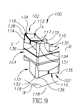
Further reference is made to Figures 8-11, depicting various views of the
cutting
insert 100, according to an embodiment of the present invention. The cutting
insert 100 has a
longitudinal insert axis A extending perpendicular to an insert transverse mid
plane P. The mid
plane P is defined by intersecting transverse insert axes B, C which are
perpendicular to each
other and also to the longitudinal insert axis A. The cutting insert 100 has
two end surfaces 102
and a peripheral surface 104 extending therebetween. The end surfaces 102 are
located on
opposite sides of the mid plane P, face in opposite directions and are
intersected by the
longitudinal insert axis A.
The cutting insert 100 includes two insert portions 106, each insert portion
106 located
on an opposite side of the mid plane P. In each insert portion 106, a cutting
protrusion 110
extends longitudinally from one of the end surfaces 102 in the direction of
the mid-plane P.
Each cutting protrusion 110 has a rear surface 115, an oppositely facing
relief surface 114 and a
rake surface 112. The rake surface 112 faces in a direction away from the mid
plane P and
generally in a direction of the longitudinal insert axis A and the relief
surface 114 faces in a
direction away from the longitudinal insert axis A. A main cutting edge 116 is
formed at the
intersection of the rake surface 112 and the relief surface 114. In a
particular embodiment, as
shown in the drawings of the present application, each main cutting edge 116
has two angled
sub-edges 117, forming a V-shape main cutting edge 116. Each rake surface 112
may further
- 4 -
CA 02924419 2016-03-15
WO 2015/063756
PCT/1L2014/050874
have two angled sub faces 120, forming a V-shape rake surface 112. Each insert
portion 106
includes a clamping recess 108 formed along the rear surface 115 of the
cutting protrusion 110,
(i.e., on the opposite side of the cutting protrusion 110 than the relief
surface 114). In some
embodiments, the clamping recess 108 may be located adjacent to the mid plane
P.
With particular reference to Figure 9, each main cutting edge 116 extends
between two
main cutting edge ends 136. A corner cutting edge 131 extends from the main
cutting edge
end 136 towards a corner cutting edge extremity 132. A secondary cutting edge
134 extends
from the corner cutting edge extremity 132 along the respective rake surface
112, transversely to
the main cutting edge 116.
The main cutting edge ends 136 of each main cutting edge 116 may be projected
in a
direction parallel to the insert axis A, and the line connecting these
projections is indicated in
Figure 9 as an edge projection 118. The edge projections 118 of both of the
main cutting
edges 116 form a non-zero first angle a therebetween. Thus, both of the
cutting protrusions 110
are similar to one another, located on opposite sides of the mid plane P and
positioned at a first
angle a relative to one another. In some embodiments the first angle a may be
in the range
of 30 450 . In particular embodiments, the first angle a may be a 900 angle.
Furthermore, the rake surface 112 of each cutting protrusion 110 is located on
an
opposite end surface 102 of the cutting insert 100 (i.e., on a different one
of the end surfaces 102,
and on different sides of the mid plane P). It would be appreciated that the
cutting insert 100 has
an elongated form, with one longitudinal dimension, parallel to the insert
axis A, and two smaller
dimensions, transverse to the longitudinal dimension (e.g., extending along
the edge
projections 118).
With particular reference to Figure 8, the peripheral surface 104 of the
cutting insert 100
has two abutment recesses 122, each extending longitudinally away from a
respective clamping
recess 108 towards the opposite end surface 102. The abutment recesses 122 are
positioned to
face away from the insert axis A. In particular, each of the abutment recesses
122 is positioned
to face a different direction away from the insert axis A. Each abutment
recess 122 has at least
one insert abutment surface 124, for abutment against a respective surface in
the insert
pocket 156, as elaborated herein below. The abutment recess 122 may have two
insert abutment
surfaces 124 thereon, forming an abutment angle 13 therebetween (indicated in
Figure 8). In a
particular embodiment, the abutment angle 0 may be a 120 angle. Each abutment
recess 122
- 5 -
CA 02924419 2016-03-15
WO 2015/063756
PCT/1L2014/050874
may extend on both sides of the mid plane P such that the abutment recesses
122 overlap in the
longitudinal direction along the longitudinal insert axis A. However, the
clamping recesses 108
may not overlap along the longitudinal insert axis A.
As seen in the figures, the cutting insert 100, though indexable, is mirror
asymmetric
about the mid plane P and is rotationally asymmetric about the longitudinal
insert axis A as well
as the two intersecting transverse insert axes B, C which define the mid plane
P. Thus, the
cutting insert has symmetry only upon a rotation of 3600 (or multiples
thereof) about any of its
axes A, B and C.
An insert clamping surface 130 extends obliquely in each clamping recess 108,
from the
adjacent abutment recess 122 towards the adjacent rear surface 115. In a side
view of the cutting
insert 100, as shown for example in Figures 6 and 10, each of the insert
clamping surfaces 130
forms a clamping angle y with the insert axis A. In some embodiments, the
clamping angle y
may be an acute angle. In particular embodiments, the clamping angle y may be
in the range of
60 - 80 .
Referring back to Figures 1-7, each insert pocket 156 of the cutting tool 150
has a
pocket abutment surface 158, a pocket clamping surface 160 and a pocket
support surface 162.
When the cutting insert 100 is located within the insert pocket 156, the
pocket abutment
surface 158 receives the insert abutment surface 124 of one of the abutment
recesses 122 of the
cutting insert 100. The pocket clamping surface 160 receives the insert
clamping surface 130 of
one of the clamping recesses 108 of the cutting insert 100. The pocket support
surface 162
receives one of the rake surfaces 112 of the cutting insert 100. The insert
pocket 156 further
includes first and second pocket fixing surfaces 170, 171. The first pocket
fixing surface 170
extends from the pocket abutment surface 158 in a direction away from the
outer surface 155 of
the cutting tool body 152. The second pocket fixing surface 171 is located
opposite to, and faces
the first pocket fixing surface 170. The insert pocket has a fastening bore
174 located adjacent to
the pocket fixing surfaces 170, 171, and extending in a direction away from
the outer surface 155
of the cutting tool body 152.
The cutting tool 150 further includes a clamping member 164 for fastening the
cutting
insert 100 against the insert pocket 156. The clamping member 164 has an
elongated shape, with
a member clamping surface 166 at a forward end thereof, and first and second
member fixing
surfaces 172, 173 located rearwardly from the member clamping surface 166. The
clamping
- 6 -
CA 02924419 2016-03-15
WO 2015/063756
PCT/1L2014/050874
member 164 also has a through hole 176 passing there through, extending along
and passing
between the member fixing surfaces 172, 173.
When the cutting insert 100 is placed in the insert pocket 156, the clamping
member 164 is placed with the member clamping surface 166 facing the insert
clamping
surface 130, and a fastening screw 178 between the clamping member 164 and the
insert
pocket 156. The fastening screw 178 is threaded in the through hole 176 of the
clamping
member 164, and in the fastening bore 174 of the insert pocket 156. The
fastening screw 178
may be actuated with a key inserted via an opening of the through hole 176 of
the clamping
member 164.
When the fastening screw 178 is fastened (e.g., as shown in the partially
transparent
Figures 5 and 6), the clamping member 164 is tightened to the insert pocket
156 such that the
clamping member fixing surfaces 172, 173 contact the respective pocket fixing
surfaces 170, 171, and the member clamping surface 166 presses against an
operative one of the
insert clamping surfaces 130 of the cutting insert 100. The member clamping
surface 166
thereby applies a clamping force F on the operative insert clamping surface
130, to ensure firm
clamping of the cutting insert 100 to the insert pocket 156. The cutting
insert 100 is thus devoid
of a clamping through hole, and it is attached to the insert pocket 156 by
external clamping only,
applied by the clamping member 164. Because of the clamping angle y between
the operative
insert clamping surface 130 and the insert axis A, the force F has a force
component aimed
towards the holder body 152, thereby retaining the cutting insert 100 forced
towards the holder
body 152.
The fastening screw 178 may have two spaced apart threaded portions 180, for
threadingly engaging respective threaded surfaces along the through hole 176
and the fastening
bore 174. One of the threaded portions 180 of the fastening screw 178 is for
left-hand threading
while the other threaded portion 180 is for right-hand threading (i.e.,
opposite threading
directions for attaching the clamping member 164 to the insert pocket 156). In
another
embodiment, the fastening screw may have a threaded portion and a screw head,
the threaded
portion engaging a respective threaded portion in the fastening bore 174, and
the screw head
adapted to press against a respective surface in the through hole 176. It is
noted that the pocket
fixing surfaces 170, 171 are constructed to prevent movement of the clamping
member 164
transversely to the through bore 176.
- 7 -
CA 02924419 2016-03-15
WO 2015/063756
PCT/1L2014/050874
When the cutting tool 150 is in an operational configuration, i.e., when the
cutting
insert 100 is mounted in the insert pocket 156 (Figures 1, 3 and 5-7), one of
the cutting
protrusions 110 is operational, while the other cutting protrusion 110 is non-
operational. Since
the rake surfaces 112 of the cutting protrusions 110 are located on different
end surfaces 102 of
the cutting insert 100, metal chips removed from the work piece by the cutting
edges of the
operational cutting protrusion 110 are formed as far away as possible from
cutting edges of the
non-operative cutting protrusion 110. Thereby contact is avoided between the
cutting edges of
the non-operative cutting protrusion 110 and the removed metal chips, such
contact which may
damage the cutting edges of the non-operative cutting protrusion 110.
As elaborated above, the end surfaces 102 and the peripheral surface 104 of
the cutting
insert 100 according to the present invention have a plurality of irregular
surfaces, recesses,
corners, intersections, and the like. Therefore, the production of such a
cutting insert 100 may be
achieved by injection molding, as producing such a cutting insert 100 by press
molding would
likely be more difficult.
When the cutting insert 100 is viewed along the mid-plane P, facing one of the
relief
surfaces 114 (e.g., Figures 7 and 11), an edge width D extending between the
corner cutting edge
extremities 132, is the largest dimension of the cutting insert 100
perpendicular to the
longitudinal insert axis A. Thus, the cutting insert 100 may perform metal
cutting, such as
slotting, along the entire edge width D, without obstruction of the non-
operative cutting
protrusion 110.
The cutting tool 150 depicted in Figures 1-7 is a rotary tool having a central
axis of
rotation R, and the outer surface 155 of the cutting tool body 152 is the
circumferential surface
of the rotary tool. In the rotary tool, the tool body 152 is coupled with a
tool shank 168
extending along the axis of rotation R. It would be appreciated that the
present invention could
be equally implemented in other types of cutting tools, other than rotary
cutting tools.
While the present invention has been described with reference to one or more
specific
embodiments, the description is intended to be illustrative as a whole and is
not to be construed
as limiting the invention to the embodiments shown. It is appreciated that
various modifications
may occur to those skilled in the art that, while not specifically shown
herein, are nevertheless
within the scope of the invention.
- 8 -