Note: Descriptions are shown in the official language in which they were submitted.
CA 02924615 2016-03-16
-1 -
TOOTH IMPLANT
BACKGROUND OF THE INVENTION
1. Field of Invention
The present invention relates to tooth implants in general and in particular
to a
method and apparatus for
2. Description of Related Art
The present invention is directed to an endosseous (endosteal) dental implant
and a method of implantation thereof. Most endosteal dental implants are
generally made of a body of elongated shape installed in a recess formed in
the jawbone and they have a means for anchoring the implant within the bone
as well as a means for receiving a prosthetic tooth. Generally, endosteal
dental implants are placed by drilling an implant hole into the bone and
inserting the implant into the prepared cavity by tapping and/or screwing.
Many different types of endosteal dental implants are known in the prior art.
In particular, commonly many dental implants are formed of an insert which is
installed in the user's jaw and abutment which is screwed to the insert. A cap
may then be installed over the abutment. Such caps are commonly
permanently secured to the abutment by adhering the cap over the abutment
including the abutment screw which is used to secure the abutment to the
insert. Therefore, in order to remove the implant, the entire cap must be
removed or a hole must be drilled through the cap to access the abutment
screw. Both of these procedures will require a new cap to be prepared or the
old one repaired, which may difficult to provide an identical biting surface
to
the original cap. Disadvantageously, such bores must then thereafter be filled
with a temporary or permanent filling material. The use of such a filling
material within the bore is that that filling material must first be removed
in
order to extract the implant for future assessment or work on the patient and
the filling material adds additional time and debris to the procedure. As
such,
the aim of the present invention is to provide and implant that makes it
CA 02924615 2016-03-16
-2-
possible to address the cited drawbacks of known types of endosteal dental
implants.
SUMMARY OF THE INVENTION
According to a first embodiment of the present invention there is disclosed an
apparatus for replicating a tooth within a user's mouth comprising a threaded
insert receivable with a bore in a wearer's jaw, the threaded insert having a
first connector associated therewith and a tooth implant having a second
connector. The first and second connectors are frictionally engageable with
each other to retain the tooth implant within the user's mouth.
One of the first or second connectors may be rotationally fixed relative to
each
other. One of the first or second connectors may comprise a central cavity.
The other of the first or second connectors may comprise a retaining post
slidably receivable within the central cavity wherein the retaining post has
an
outline corresponding to the central cavity.
The central cavity may comprise a blind bore. The blind bore may include a
keyed portion. The keyed portion may include a non-cylindrical shape. The
keyed portion may comprise a groove extending longitudinally along the
retaining post. The blind bore may include a retaining portion.
The retaining portion may comprise a tubular bore having at least one
widened region. The retaining portion may include a plurality of biased
fingers
extending into the central cavity at a location corresponding to a groove
around the retaining post. The central cavity may be located within an insert
sleeve receivable within the threaded insert.
The apparatus may further comprise a washer between the insert and the
tooth implant. The washer may be compressible. The apparatus may further
comprise a flexible sleeve between the post and the cavity.
CA 02924615 2016-03-16
-3-
Other aspects and features of the present invention will become apparent to
those ordinarily skilled in the art upon review of the following description
of
specific embodiments of the invention in conjunction with the accompanying
figures.
BRIEF DESCRIPTION OF THE DRAWINGS
In drawings which illustrate embodiments of the invention wherein similar
characters of reference denote corresponding parts in each view,
Figure 1 is an exploded view of a tooth implant according to a first
embodiment of the present invention.
Figure 2 is a cross-sectional view of the threaded insert of the
implant of
Figure 1.
Figure 3 is across-sectional view of the tooth insert and threaded
insert as
assembled together.
Figure 4a is a top view of the alternative embodiments of the insert cavity
opening.
Figure 4b is a top view of the alternative embodiments of the insert
cavity
opening.
Figure 4c is a top view of the alternative embodiments of the insert
cavity
opening.
Figure 4d is a top view of the alternative embodiments of the insert
cavity
opening.
Figure 5 is a cross-sectional view of a tooth implant according to a
first
embodiment of the present invention.
Figure 6 is a bottom view of an opening in the tooth insert of Figure 5.
Figure 7 is an exploded view of a tooth implant according to a first
embodiment of the present invention.
Figure 8 is detailed perspective view of the retaining post of
Figure 7
Figure 9 is a cross sectional view of the tooth implant of Figure 7
DETAILED DESCRIPTION
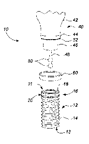
Referring to Figure 1, an apparatus for replacing a tooth according to a first
embodiment of the invention is shown generally at 10. Turning to Fig. 1, the
CA 02924615 2016-03-16
-4-
apparatus 10 comprises an threaded insert 12 adapted to be installed within
the jaw of a patient and a tooth insert 40 which is slidably received within
the
threaded insert 12.
The threaded insert 12 comprises a substantially cylindrical member
extending between top and bottom ends, 11 and 13, respectively with a
threaded exterior 14 proximate to the bottom end 13 and a top shoulder
portion 16 proximate to the top end 11. The shoulder portion 16 includes a
top platform 18 and an annular groove 20 therearound as will be more fully
described below. The threaded insert 12 is preferably made from zirconia, but
may be made from any other suitable dental implant material as are
commonly known. The threaded insert 12 is inserted into a bore in a patient's
jaw (not shown) with the bottom end 13 first and thereafter screwed in such
that the only visible part of the threaded insert 12 is the shoulder portion
16.
The top platform 18 includes a bore 22 therethrough into the interior of the
threaded insert 12 with a retaining lip 24 extending therefrom towards a
center
of the bore 22.
=
As shown in 2, the threaded insert 12 is lined with an insert sleeve 30
wherein
the insert is held in place by the retaining lips 24. The insert sleeve 30 is
formed of a substantially cylindrical member having outer dimensions
corresponding to the dimensions of the bore 22. The insert includes a central
cavity 32 therein having a top keyed portion 33 and bottom retaining portion
34. The top keyed portion 33 prevents the tooth insert 40 from rotating
relative thereto while the retaining portion retains the tooth insert within
the
cavity as will be more fully described below. The insert sleeve 30 is formed
of
any suitable material, such as, by way of non-limiting example, Teflon and is
slidably received within the bore 22. The insert sleeve 30 and/or bore 22 may
also include longitudinal ridges (not shown) to prevent relative rotation
between the two.
The keyed portion 33 of the cavity 32 has a non-circular shape so as to
provide surface which will engage the tooth insert and prevent rotation
CA 02924615 2016-03-16
-5-
therebetween. As illustrated in Figures 4a through 4d, cross-section of the
keyed portion may be selected to be any suitable shape, such as, by way of
non-limiting example, octagonal 33b as illustrated in Figure 4b, hexagonal 33a
and 33c as illustrated in Figures 4a and 4c, torx 33d as illustrated in Figure
4d
or any other suitable non-circular shape, such as, by way of non-limiting
example, oval, triangular, rectangular, irregular or the like. Optionally, the
keyed portion 33 of the cavity may also include a ridge 72 extending
therealong as illustrated in Figure 6 adapted to fit a corresponding slot in
the
retaining post.
The retaining portion 34 comprises a narrowed portion of the cavity having a
substantially cylindrical profile. Retaining portion 34 includes at least one
widened region 36 located therealong. As illustrated, the retaining portion 34
may include two widened regions 36 although it will be appreciated that one
or more than two may also be used. The widened regions 36 may be
substantially spherical as illustrated although other cross-sectional profiles
may be used as well.
With reference to Figure 1, the tooth insert 40 comprises a top body 42
corresponding to the tooth which is to be replaced. The top body 42 may be
formed of any suitable means as are commonly known in the art for creating
replicas of missing or extracted teeth. The tooth insert 40 also includes a
platform 44 which is secured to the bottom of the top body 42. The platform
44 is formed of any suitable material, such as, by way of non-limiting
example,
zirconia. Extending from a lower edge of the platform 44 is a key 46 having
an outline corresponding to the keyed portion 33 of the insert sleeve 30.
Furthermore, a retaining post 48 extends below the keyed portion 33 in a
position and size corresponding to the retaining portion 34 of the insert. In
particular, the retaining post 48 has an outer cylindrical shape corresponding
to the retaining portion 34 with widened flanges 50 located therealong as
positions corresponding to the widened regions 36 of the insert sleeve 30.
The width of the widened flanges 50 is selected to be greater than the
diameter of the main portions of the retaining portions 34 so as to retain the
CA 02924615 2016-03-16
-6-
widened flanges 50 within the widened regions 36 and thereby prevent
unwanted removal of the tooth implant as will be more fully described below.
As illustrated, the tooth insert 40 may also include an o-ring 52 or other
suitable seal around the bottom outside edge of the platform 44. Optionally,
the platform 44 may include a silicon sleeve 60 adapted to be received
therearound as will be more fully described below.
In operation, the threaded insert 12 is threadably installed within a bore in
a
patient's jaw according to known methods. Thereafter, the insert sleeve 30 is
installed within the bore 22 thereof. The orientation of the keyed portion 33
of
the cavity may then be checked utilizing methods known in the prior art, such
as the use of an indicator cap. From the orientation of the keyed portion 33
and the tooth to be replaced, the tooth insert 40 may be prepared to
correspond to the tooth to be replaced and with the keyed portion 46 and
retaining post 48 positioned relative to the top body 42 to position the tooth
as
desired. Once prepared, the silicon sleeve 60 may be installed around the
platform 44 and rolled up to expose the bottom edge thereof. The tooth insert
40 may then be inserted into the cavity 32 by aligning the keyed portion 46 of
the tooth insert 40 with the keyed portion 33 of the cavity 32. The retaining
post 48 is then pressed into the retaining portion 34 of the cavity such that
the
material of the insert sleeve 30 is deformed to permit the widened flanges 50
to be positioned into the widened regions 36 of the cavity. Such a position is
illustrated in Figure 3 wherein the o-ring 52 is positioned between the
platform
44 of the tooth insert 40 and the top platform 18 of the threaded insert 12.
Thereafter the sleeve 60 may be rolled down to cover the gap between the
tooth insert and the threaded insert 12 such that a bottom ridge 62 on the
silicon sleeve is engaged within the annular groove 20.
Optionally as illustrated in Figure 5, the tooth insert 40 may include the
central
cavity 32 wherein the retaining post 48 extends from the threaded insert 12.
As illustrated in Figure 5, the retaining post 48 may include an annular
groove
74 therearound wherein the central cavity 32 includes a plurality of inwardly
biased fingers 76 extending therefrom at a position adapted to engage within
CA 02924615 2016-03-16
-7-
the groove 74 and retain the tooth insert thereon. As illustrated in Figure 5,
the apparatus may optionally include a silicone washer 70 or other suitable
compression cushioning device between the threaded insert 12 and the tooth
insert 40.
Turning now to Figures 7 through 9, an optional embodiment of the present
invention is illustrated in which as separate retaining post 90 is provided as
a
separate element which may be secured to the threaded insert 12. In
particular, the threaded insert 12 may include a threaded central cavity 32
extending thereinto corresponding to a threaded post 92 extending from the
bottom of the retaining post 90. The assembly of Figures 7 through 9 also
includes a tooth insert 110 with a cavity 112 thereinto sized to be received
upon the retaining post 90 with a gasket sleeve 100 therebetween.
As illustrated in Figure 8, the retaining post 90 may include a rounded top
end
94 and an outwardly flared bottom end 96. As illustrated in Figure 7, the
bottom may have an outwardly outer surface which is oriented at an angle
generally indicated at 98 of between 20 and 45 degrees below horizontal, the
purpose of which will be more fully described below. The retaining post 90
may have a substantially circular cross section with one or more optional
groove 84 extending longitudinally along one side thereof for providing
resistance to rotation of the tooth insert 40. The groove 84 may optionally
include secondary groove 86 therein proximate to a bottom end thereof, the
purpose of which will be more fully described below. An optional
identification
of the retaining post 89 may also be included thereon, such as by way of non-
limiting example, a serial number, bar code or the like.
The gasket sleeve 100 may be formed of any suitable material, such as
Teflon or the like so as to be flexible. The thickness of the gasket sleeve
100 is selected to be greater than the difference between the radius of the
cavity 32 and the retaining post 90 so as to cause an interference fit
therebetween, such as approximately 0.0004 inches (10 microns). As
illustrated in Figure 9, the gasket sleeve 100 may optionally include a
thicker
CA 02924615 2016-03-16
-8-
portion 102 corresponding to the groove 84 extending along the retaining
post.
In operation, after the threaded insert 12 is located within the jaw of the
patient according to known methods, the retaining post 90 is threadably
secured onto the threaded insert 12 by threadably connecting the threaded
post 92 onto the threaded cavity 32. Thereafter, the tooth insert 110 may be
test fitted onto the retaining post 90 for alignment and height. The height of
the tooth insert 110 may be adjusted by removing material from the bottom
114 of the tooth insert. Once the alignment and height of the tooth insert 110
is correct the gasket sleeve 100 may be inserted into the cavity 112 and
retained therein by a light cement after which the alignment of the tooth
insert
110 within the mouth of the patient may again be checked and adjusted. By
removing material from the bottom 114 of the tooth insert or adjusting the
orientation of the gasket sleeve 100 within the cavity 112. Once the
orientation and height of the tooth insert 110 is acceptable, a key 88 is then
positioned under the gasket sleeve at a position corresponding to the
secondary groove 86 and the tooth insert 110 pressed over the retaining post
90 until the key 88 is positioned within the secondary groove 86 so as to
extrude the gasket sleeve 100 into the groove 84 and secondary groove 86
thereby retaining the tooth insert 110 on the retaining post 90. When a tooth
insert 110 is desired to be removed, one or more wedges 120 may be forced
between the bottom 114 of the tooth insert 110 and the flared bottom end 96
of the retaining post 90 so as to separate the two after which the tooth
insert
may be pulled off the retaining post.
While specific embodiments of the invention have been described and
illustrated, such embodiments should be considered illustrative of the
invention only and not as limiting the invention as construed in accordance
with the accompanying claims.