Note: Descriptions are shown in the official language in which they were submitted.
CA 02924739 2016-03-18
WO 2015/040553
PCT/IB2014/064591
1
DESCRIPTION
APPARATUS AND METHOD FOR PACKING A PRODUCT IN A
CONTAINER COMPRISING AN EXTERNAL BODY AND AN INTERNAL
BAG.
Technical field
This invention relates to an apparatus and a method for packing a product
in a container. More specifically, this invention relates to an apparatus and
a method for packing an infusion or extraction product in a container,
advantageously a single-use capsule, comprising a bag configured with
fluted sidewalls.
Background art
There are prior art apparatuses for packing coffee in a respective
container to be used in infusion machines, wherein the container is of the
type comprising an external body, and an internal bag, in particular
configured with fluted sidewalls, and containing coffee.
The prior art apparatuses comprise, basically, a frame for supporting
means for feeding the container and means for making and inserting the
bag inside the external body of the container; which are of the compact
type and comprise a single station, or means, for cutting a portion of
material for bags by means of a corresponding circular blade and a piston
for pushing the portion of material for bags into a hopper for forming the
bag with fluted sidewalls and then into an external body of the container,
which is located below the forming hopper on the means for feeding the
containers.
A drawback of these prior art machines is the inability to perfectly shape
the fluted sidewalls of the bag, which results in subsequent problems for
sealing the bag to the external body of the container and the making of
packages with a quality poor or which must be rejected, with consequent
economic losses and possible stoppages in the packing operations of the
2
apparatus.
More specifically, in these prior art apparatuses, it is necessary to use
corresponding and complex devices for arranging the bag inside the
external body of the ,container, after it has been shaped and positioned
using prior art making and inserting means.
Moreover, in these prior art machines a device is used for making and
inserting the bag which is excessively complex, difficult to assembly and
complicated in terms of maintenance and repairs.
Disclosure of the invention
This invention therefore proposes a new solution as an alternative to the
solutions known up to now and, more specifically, proposes to overcome
one or more of the above mentioned drawbacks and/or problems and/or to
meet one or more of the needs felt in the trade or inferable from the
1.5 above.
An apparatus and a method is therefore provided for packing an infusion
or extraction product in a container comprising a bag configured with fluted
sidewalls,
With an apparatus and a method according to the invention it is possible to
uncouple the step of making the bag from that of inserting the bag inside
an external body of the container, thus achieving the possibility of
performing repairs, maintenance and tests in an easier fashion and also
providing devices which perform the operations in a less complicated and
more reliable manner, with obvious advantages in terms of productivity
and the quality of the product.
Furthermore, with an apparatus and a method according to the invention it
is possible to form the bag configured with fluted sidewalls in a precise
and safe manner.
Moreover, in multi-row apparatuses it is possible to obtain high cutting
efficiencies, that is, minimising the waste material.
This invention further provides a device for making a bag configured with
Date Recue/Date Received 2021-03-10
3
fluted siciewalls,
Brief description of the drawings
These and other innovative aspects are set out in the appended claims
and the technical features and advantages are also apparent from the
detailed description which follows of a preferred, advantageous
embodiment of it which must be considered purely as a non-limiting
example. The description is made with reference to the accompanying
drawings, in which
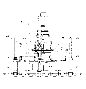
io - Figure 1 is a front view of a preferred embodiment of the apparatus
according to the invention;
- Figure 2 is a schematic perspective view of a zone for forming and
inserting bags of the preferred embodiment of the apparatus according to
the invention;
15 Figure 3 is a lateral view of the side of the upstream head of the
preferred
embodiment of the apparatus according to the invention;
- Figure 4 is a schematic top plan view of the zone for making and
inserting bags;
- Figure 5 is a schematic front view, partly in cross section, relative to
an
70 operating condition of the making means, with some components omitted
for reasons of clarity;
- Figure 6 is a partial cross section similar to that of Figure 5 and
relative to
a different operating condition of the making means, with some
components omitted for reasons of clarity;
25 - Figure 7 is a schematic lateral view showing a zone of accompaniment
of
the bags being formed in the preferred embodiment of an apparatus
according to the invention,
Detailed description of preferred embodiments of the invention
30 The accompanying drawings, in a preferred embodiment of the invention,
iliustrate an apparatus 10 for packing a product in a container to be used
Date Recue/Date Received 2021-03-10
CA 02924739 2016-03-18
WO 2015/040553
PCT/IB2014/064591
4
in respective infusion machines to obtain a corresponding beverage,
preferably in the form of coffee or a coffee-based beverage, in particular to
obtain a filter coffee. Advantageously, the container is a single-use
capsule for infusion or extraction beverages.
This container is of the type comprising an external supporting body 11,
preferably in the general shape of truncated cone, which is designed to
house and retain inside it a respective bag 13, in particular configured with
fluted sidewalls, which is in turn designed to contain a dose of product,
and which is preferably made of a suitable porous or filtering material, for
example filter paper.
More specifically, the external body 11 for supporting the container is
suitably shaped so that it can be located in corresponding shaped seats of
the infusion machine, during the operation for infusion of the beverage.
In turn, the bag 13 comprises a base, preferably circular, from which a
peripheral wall extends, flared in a direction transversal to the base and
shaped with pleats and obtained using a plurality of longitudinal fold lines.
The apparatus 10 comprises means 14 for feeding the external body 11 or
the container being set up, movable along a feed direction A, along a
respective operating path between different operating stations of the
apparatus. The feed means 14 are preferably in the form of an endless
conveyor belt 141, with articulated sectors, which is rotatable on
respective end wheels, of which only one denoted by the numeral 142 is
illustrated in the accompanying drawings.
As illustrated, the endless conveyor belt 141 defines a plurality of cavities
or recesses 143 for housing and supporting a respective external body 11
of the container.
More specifically, there are a plurality of parallel rows of recesses 143
along the feed direction A (in the embodiment illustrated there are six
parallel rows) for simultaneous and parallel feeding of a plurality of
external bodies 11 or containers being set up.
The apparatus 10 also comprises, in sequence along the feed direction A,
CA 02924739 2016-03-18
WO 2015/040553
PCT/IB2014/064591
a station 16 for making and inserting the bag 13 inside the external body
11 of the container, a joining station 18 to join, in particular to seal, the
bag
13 to the external body 11 of the container, a filling station 20 to fill the
bag
with a dose of product and a closing station 21 (schematically illustrated in
5 Figure 1) for closing the external body with a closing sheet.
The apparatus 10 also comprises a fixed frame 12 which supports the
feeding means 14, the station 16 for making and inserting the bag 13, the
joining station 18, the filling station 20 and the closing station 21.
Advantageously, the station 16 for making and inserting the bag 13
comprises at least one operating unit 160 for making and inserting the bag
13 which comprises, respectively, a device 161 for making the bag 13, a
device 162 for inserting the bag 13 inside the external body 11 of the
container, and a device 163 for conveying the bag 13 from the making
device 161 to the inserting device 162.
Advantageously, the apparatus 10 comprises a first and a second
operating unit 160, 160 for making and inserting the bag 13 comprising,
respectively, a first and a second device 161 for making the bag 13, a first
and a second device 162 for inserting the bag 13 inside the external body
11 of the container, and a first and a second device 163 for conveying the
bag 13 from the first and second making device 161 to the first and
second inserting device 162, respectively.
In this way, it is possible to uncouple the operation of making the bags
from the operation of inserting the bag inside the external body of the
container, which is advantageous in terms of the quality of performing the
operations and simplifies the construction and maintenance of the devices
used.
More specifically, it is possible to obtain a bag, formed with fluted
sidewalls, which presents a better shape, as will become clearer as this
description continues, and also to obtain a better insertion of the bag
inside the external body of the container, thereby being able to omit
corresponding devices for arranging and adjusting the bag inside the
CA 02924739 2016-03-18
WO 2015/040553
PCT/IB2014/064591
6
external body of the container, as was the case with the machines
according to the prior art.
In practice, the respective devices 161, 161 for making the bag, and the
respective devices 162, 162 for inserting the bag 13 inside the external
body 11 of the container are spaced from each other along the feed
direction A and, more specifically, are longitudinally spaced from each
other.
More specifically, in the first operating unit 160, located upstream of the
second operating unit 160 along the feed direction A, the first device 162
for inserting the bag 13 inside the external body 11 of the container is
provided upstream relative to the first device 161 for making the bag along
the feed direction A.
Conversely, in the second operating unit 160, located downstream of the
first operating unit 160 along the feed direction A, the second device 162
for inserting the bag 13 is provided downstream relative to the second
device 161 for making the bag along the feed direction A.
Advantageously, the first and second units 160, 160 for making and
inserting the bag 13 inside the external body 11 of the container operate
on a single strip 15 of filter material.
More specifically, the first and second units 160, 160 for making and
inserting the bag 13 are adjacent to each other along the feed direction A
and transversally offset, more specifically transversely offset by a row of
recesses 143.
As may be inferred in particular from Figure 3, the supporting frame 12
comprises an intermediate wall 121, in particular which extends
longitudinally and which separates drives 9 of the apparatus 10 from the
operating stations of the apparatus.
With reference to Figure 1, the numeral 151 denotes rollers for driving the
belt 15 of filter material to, and from, the operating unit 160.
More specifically, the first unit 160 for making and inserting the bags 13
operates on first external bodies 11 of the containers, whilst the second
CA 02924739 2016-03-18
WO 2015/040553
PCT/IB2014/064591
7
unit 160 for making and inserting the bags 13 operates on second external
bodies 11 of the containers, the first external bodies 11 of the containers
being offset relative to the second external bodies 11 of the containers in
the feed direction A, in particular transversely to the feed direction A.
Correspondingly, as will become clearer as this description continues,
respective parts or components of the first and second operating unit 160,
160 for making and inserting the bags 13 are offset from each other
transversely to the feed direction A.
More specifically, as illustrated, the first operating unit 160 operates on
first three external bodies 11, whilst the second unit 160 operates on
second three external bodies 11, which, however, are positioned on
interposed, or offset, rows relative to the rows of the first three external
bodies 11 on which the first unit 160 operates.
In practice, the respective making and inserting unit 160, 160 feeds the
corresponding bags to the respective first external bodies 11 which are
located, in the feed direction A, upstream and to the second external
bodies 11 which are located, in the same feed direction A, downstream.
As may be well inferred from Figure 4, the first and second devices 161,
161 for making the bags 13 of the first and second units 160, 160 are
provided mutually adjacent so as to separate, in particular to cut, from a
single strip 15 of filter material corresponding portions 17, in particular
disc
or circular-shaped, for making corresponding bags 13.
Advantageously, the devices 161, 161 for making the bags 13 cut, in the
strip 15 of filter material, respective portions 17 for the bag 13, which are
offset from each other, in particular along a direction transversal to the
feed direction A. In this way, it is possible to obtain a better use of the
strip
15 with advantageous saving of material.
More specifically, advantageously, the devices 161, 161 for making the
bag of the first and second units 160, 160 comprise respective means
1610 for cutting respective portions 17 for the bag 13, the cutting means
1610 being positioned in such a way as to make, respectively, first
CA 02924739 2016-03-18
WO 2015/040553
PCT/IB2014/064591
8
portions 17 and second portions 17. The first portion 17 and the second
portions 17 are spaced along the feed direction A and offset from each
other along a direction transversal to the feed direction A.
The cutting means 1610 of the first making devices 161 of the first
operating unit 160 are positioned substantially aligned along a first axis
Y1, advantageously perpendicular to the feed direction A of the external
bodies 11, whilst the cutting means 1610 of the second making devices
161 of the second operating unit 160 are positioned substantially aligned
along a second direction Y2, parallel to the first direction Y1,
advantageously perpendicular to the feed direction A.
Consequently, the first portions 17 made by the cutting means 1610 of the
first making devices 161 of the first operating unit 160 have centres which
lie on the first direction Y1, and the second portions 17 for the bag made
by cutting means 1610 of the second making devices 161 of the second
operating unit 160 have centres which lie on the second direction Y2,
respectively.
Advantageously, the first direction Y1 and the second direction Y2 are
spaced by less than the diameter of a portion 17 for the bag.
Generally speaking, in alternative embodiments not illustrated, the cutting
means 1610 may be designed to make portions 17 having a shape
different from the circular shape. In these alternative embodiments, the
cutting means 1610 of the first making device 161 make first non-circular
portions 17 aligned along the first direction Y1, whilst the cutting means
1610 of the second making device 161 make second non-circular portions
17 aligned along the second direction Y2, the first direction Y1 and the
second direction Y2 being spaced less than a maximum dimension along
the feed direction A of the non-circular portions 17.
In general, providing the cutting means 1610 of the first operating unit 160
and the cutting means 1610 of the second operating unit 160 offset
transversely to the feed direction A makes it possible to minimize the
waste. In other words, it is possible to make portions 17 on the strip 15
CA 02924739 2016-03-18
WO 2015/040553
PCT/IB2014/064591
9
spaced at less than the distance between two successive external bodies
11 positioned on the same row of the feed means 14.
In this way, it is possible to use a strip 15 with reduced transversal
dimensions and, at the same time, use the strip 15 in an optimum manner
also in the feed direction A.
More in detail, the cutting means 1610 comprise a blade, or punch, 1611,
advantageously circular, which acts in conjunction with a counter-blade, or
die, 1612.
The die 1612 is advantageously located at an upper end of the forming
means, advantageously a forming hopper 1613, in which the portion 17 for
the bag 13 is pushed by pushing means to be shaped with fluted
sidewalls. Advantageously, the pushing means comprise a corresponding
piston 1614. The piston 1614 is movable coaxially to the respective punch
1611.
The device 161 for making the bag 13 comprises at least one piston 1614
designed to engage a face, in particular an upper face, of the portion 17
for the bag and to push the portion 17 for the bag in the corresponding
forming means, advantageously in the forming hopper 1613.
Advantageously, the device 161 for making the bag 13 comprises
accompanying means, which act in conjunction with the pushing means, to
accompany the portion 17 for the bag through the corresponding forming
means 1613.
More specifically, the accompanying means comprise an additional piston
1615 designed to engage with a face, in particular a lower face, of the
portion 17 for the bag. The additional piston 1615 is designed to
accompany the portion 17 for the bag through the forming hopper 1613.
In practice, retaining the portion 17 for the bag between opposite means
during insertion into the forming means 1613 prevents the portion 17 from
remaining retained, or fixed, on one side, thereby resulting in bags which
are deformed or not fully formed, as is the case with the machines
according to the prior art.
CA 02924739 2016-03-18
WO 2015/040553
PCT/1B2014/064591
More specifically, the additional piston 1615 is movable between a raised
position, in which it extends inside the forming hopper 1613, and a
lowered position, to transfer the bag 17, with fluted sidewalls, to the
conveying device 163.
5 The additional piston 1615 is moved in phase coordination with the piston
1614 for conveying the portion 17 gradually inside the forming means
1613.
In other words, the additional piston 1615 is moved in phase coordination
with the piston 1614 for clamping for forcing the portion 17 inside the
10 forming means, or forming hopper 1613.
During the forming step, the portion 17 is retained by, and between, the
pushing means and the accompanying means, advantageously between
the piston 1614 and the additional piston 1615.
The forming hopper 1613 comprises suitable projections for folding the
portion 17 with fluted sidewalls.
As may be inferred, the additional piston 1615, whilst accompanying the
portion 17, moving vertically, passes through a corresponding seat 1631 of
the conveying means 163 located below the forming hopper 1613.
In the lowered position, illustrated in Figure 6, the additional piston 1615
is
under the corresponding seat 1631 of the conveying means 163, not
interfering with the conveying means 163 which transfer the bags 13
towards the inserting means 162.
Advantageously, as illustrated, the conveying device 163 moves in a
horizontal plane. Advantageously, the horizontal plane is parallel to a
plane on which the external bodies 11 of the containers lie, that is, above
the means 14 for feeding the external bodies 11 and beneath the forming
hopper 1613.
The conveying device 163 comprises an endless supporting belt 1632,
carried by corresponding drive and transmission pulleys 1633, the endless
supporting belt 1632 supporting a plurality of seats 1631, which are
designed to be positioned, alternately, at the making means 161 and the
11
inserting means 162. The endless supporting belt 1632 moves the plurality of
seats 1631 on a
horizontal plane parallel with the feed direction A, that is, above the feed
means 14 of the external
bodies 11 and below the forming hopper 1613.
More in detail, the respective seat 1631 of the conveying means 163 comprises
a corresponding
through hole for housing the bag 13, suitably sized for retaining the
respective bag 13 by
interference.
As mentioned, the apparatus illustrated in the drawings comprises a first
conveying device 163
and a second conveying device 163, which 10 comprise, respectively, a first
and a second endless
supporting belt 1632, rotating in opposite directions, on a horizontal plane,
above the feed means
14. Alternatively, the endless supporting belts rotate in the same direction,
with an adjustment in
the distance between directions or lines Y1 and Y2 to provide necessary
clearance. Each endless
supporting belt 1632 supports at least one seat 1631. Advantageously, each
belt supports a
plurality of seats 1631.
More specifically, the first endless supporting belt 1632 supports a first
series of seats 1631 and
the second endless supporting belt 1632 supports a second series of seats
1631.
Advantageously, the first series of seats 1631 conveys the bags 13 from the
first making device
161 of the first operating unit 160 upstream of the feed direction A at the
first inserting device 162,
whilst the second series of seats 1631 conveys the bags 13 from the second
making device 161 of
the second operating unit 160 downstream of the feed direction A at the second
device 162 for
inserting the bag.
Advantageously, the first and the second device 162, 162 for inserting bag 13
inside the external
body 11 of the container comprise relative first and second means for engaging
and pushing the
bag formed with fluted sidewalls inside the respective external body 11 of the
container.
Advantageously, the means for engaging and pushing the bag formed with fluted
sidewalls inside
the respective body 11 of the container comprise respective pushers, for
example respective pistons
passing through the respective seat 1631 supporting the conveying devices 163.
The engaging
Date Recue/Date Received 2021-03-10
CA 02924739 2016-03-18
WO 2015/040553
PCT/1B2014/064591
12
and pushing means are also designed to pass through a corresponding
tubular body 1622 provided between the respective supporting seat 1631
of the conveying devices 163 and the housing and supporting seat 143 of
the feed means 14.
As illustrated, the means for engaging and pushing the bags formed with
fluted sidewalls inside the respective external body of the container are
carried by a corresponding and shared frame 1623, which is driven by a
corresponding crank mechanism 1624.
In the embodiment illustrated, the first and second engaging and pushing
means each comprise three pushers 1621.
In turn, the pushers 1621 are driven along vertical directions, to push the
bags 13 from the top downwards inside a respective external body 11.
Advantageously, the pushers 1621 of the first and second engaging and
pushing means are positioned on rows transversal to the feed direction A
of the containers. More specifically, the pushers 1621 of the first engaging
and pushing means are positioned along a first row upstream of the
respective first device 161 for making the bag 13, whilst the pushers
1621of the second engaging and pushing means are positioned along a
second row downstream of the respective second device 161 for making
the bag 13.
More specifically, the pushers 1621 of the first row are positioned in
alternating rows of seats 143, and the pushers 1621 of the second row are
positioned in alternating rows of seats 143 which are different from those
of the first row of pushers 1621.
In other words, a first half of external bodies present on an articulated
sector of the endless conveyor belt 141 are fed with a respective bag 13
from the first row of pushers 1621, whilst a second half of containers
present on the articulated sector of the endless conveyor belt 141 are fed
with a respective bag 13 from the second row of pushers 1621.
According to the invention, a method is also provided for packing an
infusion or extraction product in a container, advantageously a single-use
CA 02924739 2016-03-18
WO 2015/040553
PCT/1B2014/064591
13
capsule for infusion or extraction beverages, comprising an external body
11 and a bag 13 made of suitable porous and/or filter material and
configured with fluted sidewalls.
The method according to the invention comprises the steps of feeding a
plurality of external bodies 11 of containers according to a plurality of rows
parallel inside respective seats 143 of means 14 for feeding along a feed
direction A. feeding a strip 15 of filter material; - obtaining, by cutting,
from
the strip of filter material a plurality of portions 17 designed to make a bag
with fluted sidewalls; - folding the portions 17 to form corresponding bags
13 with fluted sidewalls at a device 161 for making the bag 13; - inserting
the bags 13 in corresponding seats 1631 of a conveying device 163; -
moving the seats 1631, upstream or downstream of the device 161 for
making the bag 13 with respect to the feed direction A, for positioning the
bags 13 above corresponding external bodies 11; and inserting the bags
13 inside corresponding external bodies 11 housed inside the respective
seats 143 of the feed means 14.
Advantageously, the step of folding the portions 17 to form corresponding
bags 13 configured with fluted sidewalls comprises clamping the portions
17 between pushing means, for example a piston 1614 designed to
engage an upper face of the portion 17 and engaging means, for example
an additional piston 1615, designed to engage a lower face of the portion
17 and force the portion 17 clamped in this way inside forming means, for
example a forming hopper 1613.
Advantageously, the step of obtaining, by cutting, from the strip 15 of filter
material a plurality of portions 17 designed to make a bag 13 with fluted
sidewalls comprises obtaining, by cutting, first portions 17 aligned along a
first direction Y1 and second portions 17)aligned along a second direction
Y2, parallel to the first direction Y1.
Advantageously, the first Y1 and the second Y2 direction are mutually
parallel and transversal to the feed direction A.
As indicated above, it is possible to obtain, by cutting, first portions 17
and
CA 02924739 2016-03-18
WO 2015/040553
PCT/1B2014/064591
14
second portions 17 from a same strip 15 of filter material. Advantageously,
the first portions 17 are offset relative to the second portions 17 along a
direction at right angles to the feed direction A.
Advantageously, the method comprises inserting the bags 13 obtained
from the first portions 17 inside first external bodies 11 and the bags 13
obtained from the second portions 17 inside second external bodies 11,
the first external bodies 11 being offset along the feed direction A relative
to the second external bodies 11.
Advantageously, the first external bodies 11 are positioned upstream of
the second external bodies 11.
The invention described above is susceptible of industrial application. It
would be obvious to one skilled in the art that several changes and
modifications can be made to the invention without departing from the
spirit and scope of the invention, described in depth above. It is also easy
to imagine further embodiments of the invention comprising one or more of
the features described herein. Moreover, it will be understood that all the
details of the invention may be substituted for technically equivalent
elements.