Note: Descriptions are shown in the official language in which they were submitted.
CA 02925025 2016-03-21
1
ITEM OF SEATING FURNITURE
The invention relates to an item of seating furniture with a
sitting surface which is mounted on a frame structure and which
can be lifted from a lower position to an upper position by
means of a lifting device.
In order to make it easier for older persons or persons with
impaired mobility to sit down on an item of seating furniture or
to get up from an item of seating furniture devices have become
known in which the sitting surface of the item of seating
furniture is adjustable in height.
From WO 2011/144507 Al an item of seating furniture of this
type with such an aid for standing up is known in which spring
elements are arranged in the chair legs. When standing up the
sitting surface is raised as a result of the spring force and
tilted forwards which makes it easier to leave the item of
seating furniture. Sitting down in the item of seating furniture
is also made more comfortable.
This item of seating furniture has become well established
in practice in order to make it possible for persons with
restricted mobility to sit down and stand up by themselves.
Compared with this, the aim of the present invention is to
create a cost-effectively manufacturable item of seating
furniture of the type described in the introduction, in which
the natural course of movement during standing up or sitting
down is supported with simply designed means.
In accordance with the invention the lifting device has a
scissors mechanism with at least two limb parts which can pivot
relative to each other, wherein an actuator acts on at least one
of the limb parts.
Accordingly, for raising the sitting surface the item of
seating furniture according to the invention comprises a
scissors mechanism which has at least two limb parts which can
be pivoted about a common pivot axis. The limb parts are
arranged between the frame structure and the sitting surface so
CA 02925025 2016-03-21
2
that the sitting surface can be moved between the lower position
and the upper position by means of the limb parts. To support
the standing up movement, the scissors mechanism arranged
preferably under the sitting surface is connected to an actuator
so that the sitting surface is lifted with the aid of the
actuator. In the lower position of the sitting surface the limb
parts are arranged at a first smaller angle and in the upper
position at a second, greater angle with regard to each other.
With this the natural course of movement when standing up from
the seating furniture can be advantageously supported.
Furthermore, entry to the item of seating furniture is
facilitated. If the user sits on the raised sitting surface and
then displaces his/her weight backwards, the sitting surface is
moved into the lower position. The lower position of the sitting
surface is therefore set up as the sitting position, whereas the
upper position of the sitting surface is designed as the getting
on or getting off position. With the aid of the scissors
mechanism a simply designed aid for standing up and sitting down
is created in an advantageous manner which has also proven to be
particularly stable and reliable. In addition, the item of
seating furniture can be produced at comparatively low cost
through which the distribution of barrier-free seating furniture
can be promoted.
Envisaged as the actuator in accordance with a particularly
preferred embodiment is a spring element, which is pre-stressed
in the lower position and acts in the direction of the upper
position. Alternatively, an electric motor, more particularly a
spindle motor can be envisaged as the actuator.
In accordance with a particularly preferred embodiment the
spring element can be arranged in at least two different angular
positions. Accordingly the angle of contact between the spring
element and the associated limb part can be changed through
pivoting the spring element. In this way the force transmission
onto the scissors mechanism can be advantageously adjusted.
CA 02925025 2016-03-21
3
Preferably the spring element can be locked in the at least two
angular positions.
In order to be able to adjust the lifting device to the
weight of a user, it is of advantage if the pre-stressing of the
spring element can be set in order to adjust the lifting force
acting on the sitting surface. The pre-stressing of the spring
element can, in particular, be adjusted by changing the
compression of the spring element which compression is present
in the lower position of the sitting surface. Hence, the pre-
stressing of the spring element can be adjusted as a function of
the weight of the user, through which the lifting force acting
on the sitting surface can be influenced.
For force transmission between the spring element and the
sitting surface it is beneficial if the one end of the spring
element is supported in a spring bearing connected to the limb
part and the other end of the spring element is supported in a
counter-bearing connected to the frame structure. To adjust the
spring force the bearing positions of the spring element can be
moved towards each other, through which the compression of the
spring element and thereby the spring force can be set.
Particularly preferable is an embodiment in which the spring
bearing is connected to the corresponding limb part of the
scissors mechanism in an articulated manner so that the angular
position of the spring element can be varied. Here, it is
particularly beneficial if the bearing positions of the spring
element are moved closer or further away from each other during
pivoting of the spring element so that the spring force of the
spring element can be changed accordingly.
To adjust the angular position of the spring element and to
set the lifting force, it is of advantage if a least one control
element is arranged between the counter-bearing of the spring
element and the frame structure wherein the length of the
control element can be varied. Through changing the length of
the control element, the angular position of the spring element
and the pre-stressing of the spring element can be adjusted in
CA 02925025 2016-03-21
4
order to adapt the lifting force acting on the sitting surface
during the standing up movement to the weight of the user.
To achieve the change in length of the control element it is
beneficial if the spring element is connected to at least one
control element for adjusting the angular position of the spring
element and for setting the lifting force.
Here it is beneficial if the control element has at least
two parts, which can be adjusted in the longitudinal direction
in relation to each other, more particularly of a gas spring or
of a threaded rod element. The parts of the control element can
on the one hand be connected to each other via a thread. This
embodiment has the advantage that the angular position of the
spring element can be adjusted continuously. Alternatively the
control element can have a manually releasable snap connection
between the parts, which has at least two snap positions at a
distance from each other in the longitudinal direction. The
control element can also be in the form of a gas spring.
According to a preferred embodiment the control element is
arranged between the counter-bearing of the spring element and
the frame structure.
Alternatively the control element can be connected in an
articulated manner to a connection arm which is connected in an
articulated manner to the counter-bearing and the frame
structure.
In order to simulate the natural course of movement when
standing up or sitting down it is beneficial if the components
of the lifting device, more particularly the limb parts of the
scissors mechanism, are arranged in such a way that the lifting
force between the lower and the upper position of the sitting
surface is essentially constant, irrespective of the angular
position of the spring element. Advantageously in this way,
irrespective of the angular position of the spring element an
essentially constantly acting force is achieved between the
lower position and the upper position. Depending on the
embodiment the lifting force can be influenced by various
CA 02925025 2016-03-21
parameters, which include, in particular, the point of contact
of the spring element on the associated limb part, the length
relationship between the limb parts, the arrangement of the
pivot axis between the limb parts and the length of the spring
5 element. The individual parameters can be coordinated with
regard to each other through routine experimental work so that
the essentially constant force is achieved independently of the
angular position of the spring element.
To transmit a lifting force to the sitting surface it is
beneficial if the spring element has a helical spring. In the
lower position of the sitting surface the helical spring is
present in a compressed state. Preferably the compression of the
helical spring can be adjusted by changing the angular position
of the spring element in order to match the lifting force on the
sitting surface to the weight of the user. Through releasing the
helical spring the limb part attached thereto is pushed upwards
so that the limb parts are pivoted with regard to each other in
order to move the sitting surface into the upper position.
Preferably the spring element is connected to a damper
element, more particularly a gas pressure spring or an oil
damper, wherein the damper element is preferably arranged inside
the spring element. With the aid of the damper element, in
particular the lifting of the sitting surface is dampened, which
reliably prevents the user being jolted out of the item of
seating furniture. In this way, a particularly simple and safe
design of the item of seating furniture can be achieved.
In order to fix the sitting surface in a predefined
position, it is beneficial if the damper element can be blocked
for locking the sitting surface. Preferably the damper element
can be blocked in any position of the sitting surface, but more
particularly in the lower position of the sitting surface. This
embodiment has the advantage that the sitting surface can also
be fixed when no weight is acting on the sitting surface.
For the manual blocking and release of the damper element it
is beneficial if the blockable damper element is connected via a
CA 02925025 2016-03-21
6
connection, more particularly a tension cable, with an
activating device, preferably in the area of an arm rest.
In accordance with a preferred embodiment the sitting
surface is designed in one part, wherein in the upper position
the sitting surface is arranged essentially horizontally or
arranged to slope forwards.
In accordance with a further preferred embodiment the one
limb part engages on a front sitting area and the other limb
part on a rear sitting area of the sitting surface, wherein the
front and rear sitting area are connected to each other in an
articulated manner. In this embodiment of the invention it is
preferably envisaged that the front edge of the front sitting
area of the sitting surface is rounded in design.
If the front and rear sitting area in the lower position of
the sitting surface are essentially arranged in one plane,
wherein the front sitting area in the upper position of the
sitting surface is inclined downwards towards the rear sitting
area, sitting down and standing up can be facilitated further.
In the upper position the rear sitting area is preferably
arranged horizontally or tilted slightly forward from the
horizontal.
In order to allow for pivoting of the limb parts when
lifting or lowering the sitting surface, at least one of the
limb parts is preferably connected in an articulated manner to a
crank lever which is mounted on the frame structure via an
articulated joint. In this way blocking of the limb parts can be
prevented in a particularly simple way. Alternatively, at least
one of the limb parts could be borne in a guide connected with
the frame structure.
To transfer particularly high lifting forces to the sitting
surface it is advantageous if the scissors mechanism, preferably
on the opposite longitudinal sides of the sitting surface, has
at least two pairs of limb parts that can be pivoted with regard
to each other.
CA 02925025 2016-03-21
7
In accordance with a particularly user-friendly embodiment,
chair legs with castors are provided which castors are each
connected to a braking device for blocking the castors. In this
way the item of seating furniture can be moved in a particularly
simple manner. With the aid of the braking device the item of
seating furniture can be fixed in its position, which is of
particular advantage if the person wants to sit down in or wants
to stand up from the item of seating furniture. It is
particularly preferable if the at least one braking device
interacts with the height position of the sitting surface in
such a way that the braking device is automatically brought into
the blocked state as soon as the sitting surface has been raised
a predetermined distance from the lower position. According to
an alternative embodiment it is envisaged that the item of
seating furniture is fitted with a brake lever that can be
operated by the user. On operating the lever a tension cable
extending into the castors is activated and releases the braking
device there.
The invention will be described in more detail below by
means of a preferred example of the embodiment shown in the
drawings, to which, however, it is not restricted. In detail, in
the drawings:
Fig. 1 shows a side view in partial cross-section of an item
of seating furniture in accordance with the invention, with a
scissors mechanism to raise the sitting surface, wherein a
spring element acting on the scissors mechanism is arranged in a
first angular position corresponding to a first, lesser lifting
force;
Fig. 2 shows a view of the item of seating furniture in fig.
1 from the front;
Fig. 3 shows a side view of the item of seating furniture in
accordance with fig. 1, 2 with the sitting surface lowered;
Fig. 4 shows a view of the item of seating furniture
according to the invention corresponding to fig. 1 with the
sitting surface raised wherein to increase the lifting force
CA 02925025 2016-03-21
8
acting on the sitting surface the spring element is pivoted into
a second angular position corresponding to a second, greater
lifting force.
Fig. 5 shows a view of the seating furniture shown in fig. 4
with the sitting surface lowered;
Fig. 6 shows a view of a preferred embodiment of the item of
seating furniture in which the spring and/or damping element is
connected via a tension cable to an activating device in the
area of an arm rest of the item of seating furniture; and
Figs. 7 to 11 show views of an item of seating furniture
corresponding to figs. 1 to 5 in an alternative form of
embodiment of the invention.
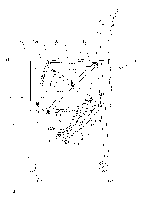
In fig. 1 to 3 an item of seating furniture 10 is shown
which comprises a frame structure 1, a backrest 11, arm rests 12
and a sitting surface 13. According to figs. 1, 2 the sitting
surface 13 of the item of seating furniture 10 is arranged in a
raised, or upper, position, which makes it easier for an
impaired person to get up from the item of seating furniture 10
or to sit down in the item of seating furniture 10. According to
fig. 3 the sitting surface 13 of the item of seating furniture
10 is arranged in a lowered or lower position which corresponds
to the essentially horizontal sitting position. To move the
sitting surface 13 between the lower position (cf. fig. 3) and
the upper position (cf. figs. 1, 2) the sitting surface 13 is
connected to a lifting device with which the natural course of
movement when standing up or sitting down is supported.
As can also be seen from figs. 1 to 3, a scissors mechanism
14 is provided as the lifting device and acts between the
underside of the sitting surface 13 and the frame structure 1.
The scissors mechanism 14 has at least one pair of interacting
limb parts 14a, 14b, wherein in the shown embodiment a further,
identical, pair of limb parts 14a', 14b' is provided. The limb
parts 14a, 14b and/or 14a', 14b' are hinged on opposite
longitudinal sides of the sitting surface 13.
CA 02925025 2016-03-21
9
As can also be seen from figs. 1 to 3, the limb parts 14a,
14b are arranged so that they can be pivoted with regard to each
other. For this, the limb parts 14a, 14b are pivotably arranged
about a common axle 2 which is arranged approximately centrally
on the limb parts 14a, 14b. In order to allow the pivoting of
the limb parts 14a, 14b during the raising and lowering of the
sitting surface 13, the one limb part 14a is connected via an
articulated joint 2' to a crank lever 14c which, via an
articulated joint 2", is mounted on the frame structure 1.
As can also be seen from figs. 1 to 3, the limb part 14b of
the scissors mechanism 14 is connected with a spring element 16a
which in the lower position of the sitting surface 13 (cf. fig.
3) is pre-stressed so that the sitting surface 13 can be moved
from the lower position into the upper position (cf. Fig. 1, 2)
with the support of the spring element 16a. In the shown
embodiment the spring element 16a is in the form of a helical
spring which will be decompressed during the movement of the
sitting surface 13 into the upper position. For force
transmission to the limb part 14b the one end of the spring
element 16a is held in a spring bearing 22 connected to limb
part 14b, and the other end of the spring element 16a is held in
a counter-bearing 23 connected with the frame structure 1.
As can also be seen from the drawing, the spring element 16a
can be arranged in at least one first angular position (cf.
figs. 1 to 3) and in a second angular position (cf. Fig. 4, 5)
different to the first angular position. By changing the angular
position of the spring element 16a, on the one hand the angle of
contact of the spring element 15a on the limb part 14b, and also
the pre-stressing of the spring element 16a can be adjusted,
through which the lifting force on the sitting surface 13 can be
matched to the weight of the user. For this, between the
counter-bearing 23 of the spring element 16a and the frame
structure 1 a control element 15 is arranged which can be
adjusted in length in order to adapt the angular position of the
spring element 16a and to set the lifting force. In the shown
CA 02925025 2016-03-21
embodiment the control element 15 has two parts 15a, 15b which
can be adjusted longitudinally with regard to each other,
wherein the one part 15b is connected in an articulated manner
to the frame structure 1 and the other part 15a is connected in
5 an articulated manner to the counter-bearing 23. In addition,
the counter-bearing 23 is attached in an articulated manner to
the frame structure 1 by means of a connection arm 15'.
As can also be seen from the drawing, the spring element 16a
can be pivoted from the first, more obtuse angular position
10 shown in figs. 1 to 3, into the second, more acute, angular
position shown in fig. 4, 5. To pivot the spring element 16a,
the parts 15a and 15b of the control element 15 are manually
pushed into each other. According to figs. 1 to 6, parts 15a,
15b form a gas spring. By adjusting the control element 15 the
distance, dependent on the length of the control element 15,
between the spring bearing 22 and the counter-bearing 23 is
shortened, through which the pre-stressing of the spring element
16a and thus the lifting force acting on the sitting surface 13
is increased. In this way the resulting lifting force can be
specifically set via the angular position of the spring element
16a. The various components of the lifting device, more
particularly the limb parts 14a, 14b, 14a', 14b' of the scissors
mechanism 14 are arranged and connected to each other in such a
way that the lifting force between the upper and the lower
position of the sitting surface 13 is essentially constant -
irrespective of the angular position of the spring element 16a.
As can also be seen from figs. 1 to 5, the spring element
16a interacts with a damper element 16b which is preferably in
the form of a gas pressure spring or oil damper. The damper
element 16b is arranged inside the spring element 16a. In the
shown embodiment the damper element 16b has a cylinder 162b
within which a piston rod 162a moves.
As can be seen from fig. 6, the damper element 16b in the
shown embodiment can be blocked, so that if required the sitting
surface 13 can be locked in a predetermined height position. For
CA 02925025 2016-03-21
11
locking or releasing, the blockable damper element 16b is
connected via a connection 223, for example a tension cable,
extending within a chair leg 6, to an activating device 231,
which in the shown example of embodiment is located in a front
end area of the arm rest 12. The movement of the activating
device 231 is transmitted via the connection 233 to a lever 232
with articulated joint 234. The lever 232 presses against a
corresponding activating element of the damper element 16b,
through which the blocking of the piston rod 162a relative to
the cylinder 162b is released. In the blocked stated of the
damper element 16b, lifting of the sitting surface 13 can be
advantageously prevented, if, for example, the person using the
item of seating furniture 10 leans forwards to pick up an object
from the floor and therefore takes the load off the sitting
surface 13.
As can also be seen from fig. 1 to 5, the one limb part 14a
is connected in an articulated manner via a profile part 3 to a
front sitting area 13a and the other limb part 14b is connected
in an articulated manner via a profile part 4 to a rear sitting
area 13b of the sitting surface 13. The front 13a and the rear
sitting area 13b are pivotably connected to each other via a
joint 5. Through this further relieving of impaired persons can
be achieved when they are sitting down. In the shown embodiment
the front sitting area 13a has a front edge which is bent
downwards. Additionally, the front sitting area 13a is much
narrower than the rear sitting area 13b.
As can also be seen from figs. 1 to 5, in the lower position
of the sitting surface 13 the front 13a and the rear sitting
area 13b are essentially arranged in one plane. Linking of the
front 13a and/or rear sitting area 13b via the limb parts 14a,
14b takes place in that the front sitting area 13a in the upper
position of the sitting surface 13 is arranged inclined
downwards with regard to the rear sitting area 13b. In the upper
position the rear sitting area 13b is also lightly tilted down
with regard to the horizontal.
CA 02925025 2016-03-21
12
As can also be seen from figs. 1 to 5 the item of seating
furniture 10 has four chair legs 6, which are each provided with
castors 17a, 17b for rolling the item of seating furniture 10 on
a floor surface. Here it is envisaged that the front castors 17a
are designed to be laterally pivotable, whereas the rear castors
17b are not laterally pivotably, but, instead, are each provided
with a braking device 18. In order to prevent the item of
seating furniture 10 rolling away backwards when a person is
sitting down or standing up, the braking device 18 is provided
which can block or release the rear castors 17b depending on the
setting. For this a manually operated braking lever can be
provided with which the braking device 18 can be locked or
unlocked.
In an alternative embodiment (not shown), it is envisaged
that the braking device 18 is automatically blocked when the
sitting surface 13 is raised by a predetermined distance, for
example 40 mm, from the lower sitting position. In this way the
item of seating furniture 10 is secured against an unintentional
(backwards) movement, whereas at the same time a movement
forwards can take place without perceptible resistance.
In figs. 7 to 11 an alternative embodiment of the invention
is shown in which in the following only the differences with
regard to the embodiment according to figs. 1 to 6 are
described. In this embodiment the control element 15 also has
parts 15a, 15b which can be adjusted with regard to each other,
but which together form a threaded rod element. The threaded rod
element can be adjusted with a hand wheel or an Allen key in
order to match the angular position of the spring element 16 to
the weight of the user.