Note: Descriptions are shown in the official language in which they were submitted.
AUTOMATED WORKFLOW CAPTURE FOR ANALYSIS AND ERROR
REPORTING IN A DRILLING APPLICATION
CROSS-REFERENCE TO RELATED APPLICATIONS
[0001] The present application claims the benefit of U.S. Provisional Patent
Application No. 61/889,872, filed on October 11,2013, titled "Method to
Capture the Oil
and Gas Field Workflows to Improve the Software".
BACKGROUND
0 1. Field of the Disclosure
[0002] The present disclosure relates generally to applications related to
activities
performed at a well site in a petroleum field, and more particularly, to
applications for
managing and reporting data related to the activities at a well site.
2. Discussion of the Related Art
[0003] Modern drilling operations may involve hundreds of activities that are
performed at the site of a well or drilling rig in a petroleum field. There
are various
software tools/applications being utilized today that assist in the recovery
of
hydrocarbons. Examples of such "drilling applications" include, but are not
limited to,
the OpenWells and OpenWells Mobile for Workovers information management and
reporting systems available from Landmark Graphics Corporation ("Landmark") of
Houston, Texas. Such applications may be used, for example, to manage and
track all of
the drilling and completion activities at a single well site or across the
entire field.
[0004] Currently, user feedback regarding the use of a drilling application
generally
requires an end-user to manually collect/document the information and report
the
information via email, phone, or using a separate online reporting system. For
example, a
user of a drilling application may report software bugs using a third-party
reporting tool,
which requires the user to report a defect in the drilling application by
manually
documenting the steps that may be used to reproduce the problem.
1
CA 2925093 2017-09-18
CA 02925093 2016-03-22
WO 2015/054155 PCT/US2014/059347
BRIEF DESCRIPTION OF THE DRAWINGS
[0005] Illustrative embodiments of the present disclosure are described in
detail below
with reference to the attached drawing figures, which are incorporated by
reference
herein and wherein:
[0006] FIG. 1 illustrates an exemplary network environment suitable for
practicing an
embodiment of the present disclosure;
[0007] FIG. 2 illustrates an exemplary client device in the network
environment of FIG.
1 for enabling automated workflow capture in a drilling application;
[0008] FIG. 3 illustrates an exemplary workflow for a user-initiated operation
related to
a well site activity, in which the user's interactions with a drilling
application are tracked
over a series of interactive windows displayed in a GUI of the drilling
application;
[0009] FIG. 4 is a process flowchart of an exemplary method for enabling
automated
workflow capture in a drilling application; and
[0010] FIG. 5 is a block diagram illustrating an exemplary computer system for
implementing the disclosed embodiments.
2
CA 02925093 2016-03-22
WO 2015/054155 PCT/1JS2014/059347
DETAILED DESCRIPTION
[00111 Embodiments of the present disclosure relate to automated workflow
capture in
a drilling application. While the present disclosure is described herein with
reference to
illustrative embodiments for particular applications, it should be understood
that
embodiments are not limited thereto. Other embodiments are possible, and
modifications
can be made to the embodiments within the spirit and scope of the teachings
herein and
additional fields in which the embodiments would be of significant utility.
Further, when
a particular feature, structure, or characteristic is described in connection
with an
embodiment, it is submitted that it is within the knowledge of one skilled in
the relevant
art to effect such feature, structure, or characteristic in connection with
other
embodiments whether or not explicitly described.
[00121 It would also be apparent to one of skill in the relevant art that the
embodiments,
as described herein, can be implemented in many different embodiments of
software,
hardware, firmware, and/or the entities illustrated in the figures. Any actual
software
code with the specialized control of hardware to implement embodiments is not
limiting
of the detailed description. Thus, the operational behavior of embodiments
will be
described with the understanding that modifications and variations of the
embodiments
are possible, given the level of detail presented herein.
[0013] In the detailed description herein, references to "one embodiment," "an
embodiment," "an example embodiment," etc., indicate that the embodiment
described
may include a particular feature, structure, or characteristic, but every
embodiment may
not necessarily include the particular feature, structure, or characteristic.
Moreover, such
phrases are not necessarily referring to the same embodiment. Further, when a
particular
feature, structure, or characteristic is described in connection with an
embodiment, it is
submitted that it is within the knowledge of one skilled in the art to effect
such feature,
structure, or characteristic in connection with other embodiments whether or
not
explicitly described.
[0014] As used herein, the term "workflow" may refer to a series of actions
that are
taken by a user ancUor a client application executable at a computing device
of the user
for completing an operation or function provided by the client application. In
one
example, the client application may be a drilling application, and the
operation may be
related to an activity performed at a well site for the exploration and/or
production of
3
CA 02925093 2016-03-22
WO 2015/054155 PCT/US2014/059347
hydrocarbons from a reservoir in a petroleum field. A single operation may
include, for
example, a sequence of steps that are to be completed by the user as part of
an interactive
workflow involving a series of interactions between the user and the
application. As will
be described in further detail below, embodiments of the present disclosure
enable such a
workflow to be captured automatically, e.g., while the user is interacting
with a graphical
user interface (GUI) of the application.
100151 The term "drilling application" is used herein to refer to any
application
program used by personnel in a petroleum field for the exploration,
development, and/or
production of subsurface hydrocarbon deposits (e.g., oil and natural gas) from
one or
more reservoirs in the field. Such a drilling application may be used by, for
example, a
supervisor of a drilling rig or other personnel associated with an oilfield
service provider
to manage and track various drilling and completion activities at one or more
well sites in
the field. Examples of such activities include, but are not limited to,
cementing, casing,
perforations, pipe tally, stimulation, and other activities related to the
operation and
maintenance of a drilling rig and the wellbore equipment used therein.
[0016] As stated above, the collection of information pertaining to workflows
in an oil
and gas field traditionally has been a manual process. For example, a
conventional
information reporting system may require a user to document individual
activities on a
daily basis and report the documented information via email or an online
interface of the
reporting system. In contrast with such conventional systems, the disclosed
embodiments
provide systems and techniques for automatically monitoring or tracking a
workflow of a
user within a drilling application in relation to an operation initiated by
the user via a
graphical user interface (GUI) of the drilling application.
[0017] In one example, a rig supervisor may use a drilling application
executable at a
tablet or other type of mobile device to collect data and generate reports
regarding an
activity on a drilling rig. Even if the user is able to generate the desired
report, the user
may have had a very difficult time in completing the task. By using the
disclosed
embodiments, the monitoring/tracking mechanism can automatically capture or
record the
user's interactions with the drilling application as part of a workflow for
the particular
operation (e.g., report generation) initiated by the user within the
application. This may
include, for example, recording, among other things, all of the user's
interactions with
4
CA 02925093 2016-03-22
WO 2015/054155 PCT/US2014/059347
respect to one or more user control elements of the GUI of the drilling
application while
the operation is performed.
[0018] As will be described in further detail below, such a
monitoring/tracking
mechanism may be used to capture workflow data related to the actions
performed by the
user via the GUI of the drilling application as well as those performed by the
drilling
application. Such workflow data may be analyzed to improve the usability and
quality of
the drilling application. For example, the recorded user-interactions and
captured data
may be viewed (or "replayed") and analyzed by support personnel for suggesting
possible
workarounds for application execution errors or other software issues that may
be
encountered during the workflow. A similar workflow analysis also may be
performed
by an application developer for determining potential modifications that may
be made to
the application in order to improve the workflow and the user experience,
e.g., by
providing the user with a more intuitive interface. In this way, the automated
workflow
capture techniques disclosed herein may provide an automated user feedback and
error
reporting mechanism for obtaining useful information related to the workflows
in a
drilling application, which can be used to implement new application features
and/or
support existing ones.
[0019] The disclosed embodiments and advantages thereof are best understood by
referring to FIGS. 1-5 of the drawings, with like reference numerals being
used for like
and corresponding parts of the various drawings. Other features and advantages
of the
disclosed embodiments will be or will become apparent to one of ordinary skill
in the art
upon examination of the following figures and detailed description. It is
intended that all
such additional features and advantages be included within the scope of the
disclosed
embodiments. Further, the illustrated figures are only exemplary and are not
intended to
assert or imply any limitation with regard to the environment, architecture,
design, or
process in which different embodiments may be implemented.
[0020] FIG. 1 illustrates an example of a network environment 100 suitable for
practicing an implementation of the subject technology. As shown in FIG. 1,
network
environment 100 includes client devices 110a, 110b, and 110c ("client devices
110a-c")
and a computing system 130. Computing system 130 may include, for example, one
or
more computing devices 132 (e.g., one or more servers) and one or more
computer-
5
CA 02925093 2016-03-22
WO 2015/054155 PCT/US2014/059347
readable storage devices 134 (e.g., one or more databases). Client devices
110a-c may
communicate with computing system 130 via a network 120.
100211 Each of client devices 110a-c can be any type of any type of computing
device
having at least one processor and a memory in the form of a computer-readable
storage
medium for storing data and instructions that can be read and executed by the
processor.
Such a computing device may also include an input interface for receiving user
input or
commands via a user input device (e.g., a mouse, QWERTY or T9 keyboard, touch-
screen, or microphone). The computing device may also include an output
interface for
outputting or presenting information via a display coupled to or integrated
with the
device. In some implementations, the input and output interface may be
combined into a
single input/output (1/0) interface. Examples of such a computing device
include, but are
not limited to, a desktop computer, a laptop computer, a smartphone, a tablet,
a personal
digital assistant (PDA), a network appliance, a media player, a navigation
device, an
email device, or a combination of any these data processing devices or other
data
processing devices.
100221 Similarly, computing device 132 can be implemented using any type of
computing device capable of sending and receiving data to and from any of
client devices
110a-c via network 120. In an embodiment, computing device 132 may be a type
of
server. Examples of such a server may include, but are not limited to, a web
server, an
application server, a proxy server, and a network server. In some
implementations,
computing device 132 may represent a group of computing devices in a server
farm.
[0023] Thus, network environment 100 may represent, for example, a distributed
client/server system in which computing device 132 is communicatively coupled
to each
of client devices 110a-c via network 120. Network 120 in this example may be
any type
of network or combination of networks for carrying data communications. Such a
network may include, for example and without limitation, a local area network,
a medium
area network, and/or a wide area network, such as the Internet. In some
implementations,
client devices 110a-c may communicate with computing device 132 via a private
network
(e.g., an "intranet") associated with a particular company or organization.
Computing
device 132 also may be communicatively coupled to storage device 134, e.g.,
via the
private network. Storage device 134 may be one or more data stores or
databases used to
store any type of data accessible by computing device 132. Such data may
include, for
6
CA 02925093 2016-03-22
WO 2015/054155 PCT/US2014/059347
example, workflow data captured at each of client devices 110a-c based on
interactions
between a user and a client application executable at each device, as will be
described in
further detail below.
[0024] In the example shown in FIG. 1, client devices 110a-c represent various
types of
computing devices in which the disclosed automated workflow capture techniques
may
be implemented. Client device 110a may be, for example, a smartphone. Client
device
110b may be, for example, a desktop computer or workstation. Client device
110c may
be, for example, a tablet or other type of handheld computer. The users of
client devices
110a-c may be associated with, for example, an oilfield services company
responsible for
managing hydrocarbon exploration and production operations in a petroleum
field. For
example, client devices 110a-c may be different computing devices used by
company
personnel to collect data and generate reports related to various activities
conducted at a
well site in the field.
[0025] In an embodiment, a client application executable at each of client
devices 110a-
c may enable a user (e.g., a rig supervisor) to initiate an operation related
to a particular
activity conducted at the well site. For example, the user may initiate the
operation by
selecting a corresponding option from a menu displayed within a GUI of the
client
application, as will be described in further detail below. As described above,
the client
application may be a drilling application used to perform one or more
operations related
to one or more activities conducted at a well site, e.g., on a drilling rig.
Such an operation
may be, for example and without limitation, a data collection and reporting
operation
related to a particular activity conducted at the well site. The collected
data or report
generated therefrom may be transmitted to computing device 132 via network
120.
Computing device 132 may store the received well site data or report within
storage
device 134, e.g., as part of a centralized repository for managing such
information.
[0026] Also, as will be described in further detail below, the drilling
application
executable at each of client devices 110a-c may provide an automated workflow
capture
functionality for automatically monitoring or tracking the interactions of the
user with the
application (e.g., via the GUI thereof). Data for a workflow related to the
user-initiated
operation may be captured at each device in real-time based on the
monitoring/tracking.
For example, such a monitoring/tracking mechanism can log the workflow in a
log file or
other data file generated based on the monitored/tracked user interactions.
The workflow
7
CA 02925093 2016-03-22
WO 2015/054155 PCT/US2014/059347
log may include, for example, a record of all of the monitored/tracked
interactions of the
user starting from when the application was launched at the client device or
the operation
was initiated by the user via an introductory screen or page initially
displayed by the
client application upon startup.
[0027] In an embodiment, the workflow log file may be automatically uploaded
to a
support site or service hosted at computing device 132 via network 120. For
example, the
drilling application executable at each of devices 110a-c may be configured to
transmit
the log file to a specified Internet Protocol (IP) address for enabling a
member of a
technical support group to review and analyze the workflow based on the
information in
the log file. Alternatively, the log file may be sent manually by the user via
email. In
an embodiment, the log file or captured data may be encrypted or encoded in a
secure
data format that is accessible to only authorized personnel and thereby
prevent
unauthorized access or disclosure of sensitive information that may be
included within
the file.
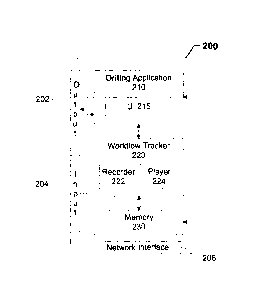
[0028] FIG. 2 is a block diagram of an exemplary client device 200 for
enabling the
automated workflow capture functionality disclosed herein. Client device 200
may
represent, for example, any of client devices 110a-c of FIG. 1, as described
above. As
shown in FIG. 2, client device 200 includes an output interface 202, an input
interface
204, a network interface 206, a drilling application 210, a workflow tracker
220, and a
memory 230. While not shown in FIG. 2, it should be appreciated that client
device 200
may include additional components for implementing the automated workflow
capture
functionality described herein and that these other components are not shown
in FIG. 2
for ease of explanation and discussion.
[0029] In an embodiment, a user may initiate or launch drilling application
210 via an
operating system interface executable at client device 200. The user may
interact with
drilling application 210 as it executes at client device 200 via a GUI 215.
GUI 215 may
be displayed or presented on a display of client device 200 via output
interface 202. GUI
215 may include, for example, an interactive content window for displaying
different
types of content (e.g., text and/or graphics). GUI 215 may also include
various user
interface (UI) controls or other elements, which may be displayed along with
the content
in the interactive content. The user may use an input device (e.g., a touch-
screen, mouse,
keyboard, or other type of user input device) to interact with any of the
displayed UI
8
CA 02925093 2016-03-22
WO 2015/054155 PCT/11S2014/059347
controls or elements of GUI 215 to initiate an operation related to a
particular well site
activity or perform different actions related to the initiated operation
within drilling
application 210.
[0030] In an embodiment, the user-initiated operation may involve multiple
steps or
actions that may need to be performed in order for the operation to be
completed. For
example, the steps/actions may be performed over a series of interactive pages
or screens
that may be presented or displayed via GUI 215 (e.g., within the interactive
window).
Each interactive page/screen in the series may correspond to one or more steps
of a
workflow for initiating and completing the operation within drilling
application 210.
Each step of the workflow may in turn correspond to an action performed by the
user
within one of the pages displayed via GUI 215. In an embodiment, the workflow
may
also include steps/actions performed by drilling application 210. Some of the
actions of
drilling application 210 may be performed, for example, in response to one or
more
actions of the user via GUI 215, e.g., with respect to a UI element or control
within a
page displayed via GUI 215.
[0031] FIG. 3 illustrates an example of a workflow 300 in which the steps for
initiating
and completing an operation related to a well site activity are performed over
a series of
pages displayed via a GUI (e.g., GUI 215) of a drilling application (e.g.,
drilling
application 210), as described above. The operation in this example may be a
data
collection and report generation operation for a well stimulation activity
performed at the
well site. The operation may involve, for example, collecting data related to
the
stimulation activity and generating a report for the activity based on the
collected well
site data. However, it should be noted that embodiments of the present
disclosure are not
intended to be limited thereto and that the disclosed embodiments may be
applied to any
operation related to any of the various activities that may be performed at a
well site.
[0032] As shown in FIG. 3, workflow 300 includes a series of interactive pages
310,
320, 330, and 340, and the user may perform one or more actions within each
page of the
series. The initial action performed by the user at the start of workflow 300
may be
initiating the operation by appropriately selecting an option 312
corresponding to the
stimulation activity from a list or menu of options for different well site
activities
displayed within interactive page 310. Additional actions performed by the
user within
successive pages may include, for example, interacting with one or more UT
elements or
9
CA 02925093 2016-03-22
WO 2015/054155 PCT/US2014/059347
controls that may be provided within a page. Such user interactions may
include, for
example, the entry of text or other type of data into one or more data fields
and selection
of one or more user options via a menu or other type of UI control displayed
within the
page. Other types of UI controls that may be provided within an interactive
page may
include, for example, navigation control buttons for navigating between
different
interactive pages (e.g., proceeding to the next page in the series or
returning to the
preceding page). Also, button controls for canceling or discontinuing the
operation prior
to completion of the operation may also be provided within each page.
[0033] Completion of the operation in this example may correspond to the
generation
of a report in a final step that may be performed by the user via interactive
page 340. The
final step may be, for example, the user's selection of a button 342 for
invoking the report
generating feature via interactive page 340. Thus, the user-initiated
operation and
workflow 300 may be considered "concluded" or "terminated" when, for example,
the
user cancels or otherwise discontinues the operation, e.g., by closing or
exiting the
drilling application at the client device. The user may cancel or discontinue
the operation
at any stage of the workflow, e.g., after one or more actions/steps are
performed but prior
to the completion of the final step.
[0034] It should be noted that while only four interactive pages are shown in
FIG. 3, the
disclosed embodiments are not intended to be limited thereto and that workflow
300 may
include additional pages depending on the particular operation initiated by
the user and/or
the actions performed or options selected by the user within each interactive
page of the
workflow for that operation. For example, one or more additional interactive
pages may
be displayed via the GUI based on the user's selection of a control button 344
for
specifying the stimulation activity in this example is a multi-stage treatment
stimulation
and adding details for each stage of the treatment.
[0035] Referring back to FIG. 2, workflow tracker 220 may automatically
monitor or
track the interactions between the user and drilling application 210 as part
of a workflow
(e.g., workflow 300 of FIG. 3) related to the user-initiated operation at
client device 200,
as described above. The monitored/tracked interactions may be based in part on
input
received from the user via input interface 204 with respect to one or more UI
controls or
elements of GUI 215. While workflow tracker 220 is shown separately from
drilling
application 210 in FIG. 2, workflow tracker 220 may be implemented as a
component of
CA 02925093 2016-03-22
WO 2015/054155 PCTfUS2014/059347
drilling application 210 in an embodiment of the present disclosure. For
example, the
disclosed monitoring/tracking mechanism may be integrated into the processor-
executable code or instructions of drilling application 210. Alternatively,
workflow
tracker 220 may be implemented as a separate application executable at client
device 200,
which may be configured to monitor or track the interactions between the user
and
drilling application 210 via an application programming interface (API) of
drilling
application 210 for enabling the automated tracking features.
[0036] In an embodiment, workflow tracker 220 may use a recorder 222 for
capturing
data for the workflow based on the interactions between the user and drilling
application
210. The workflow data may be captured starting from, for example, the point
that the
operation is initiated by the user (e.g., via interactive page 310 of FIG. 3,
as described
above) and continuing until the operation is determined to have been completed
or
otherwise concluded or discontinued. As described above, the user may have
abandoned
or discontinued the operation by closing the application prior to the
completion of the
operation (e.g., prior to the generation of the report via interactive page
340 of FIG. 3).
Alternatively, the operation may have concluded or terminated as a result of
an runtime
error that occurred in the client application during the workflow and prior to
completion
of the operation. The captured data may be stored in memory 230. The stored
workflow
data in memory 230 may be retrieved at a later time and used to perform an
analysis of
the workflow.
[0037] In an embodiment, recorder 222 may be configured to record video data,
e.g.,
capture data that may be used to replay the workflow in the form of a video
showing GUI
215 and the user's interactions with GUI 215. In some implementations, such
video data
may include a series of screenshots captured by recorder 222 on a periodic
basis. For
example, the captured screenshots may represent successive image frames of a
workflow
video captured/recorded by recorder 222 at predetermined frame rate. However,
it should
be appreciated that any of various techniques may be used to capture or record
video data
for the workflow.
[0038] In an embodiment, workflow tracker 220 may include a player 224 for
presenting a visual reproduction of the workflow based on the captured data.
In some
implementations, drilling application 210 may provide a local playback feature
enabling a
user of client device 200 to replay the workflow by playing back the recorded
video
11
CA 02925093 2016-03-22
WO 2015/054155 PCT/US2014/059347
and/or screenshots. In an example, player 224 may invoke a built-in media
player of
drilling application 210 that allows the user to view the recorded workflow
video and/or
screenshots within an interactive window of GUI 215. Alternatively, a separate
media
player may be used for viewing of the recorded video and/or screenshots. The
separate
media player may be, for example, specially configured to be able to playback
the
recorded video and/or screenshots (e.g., includes proprietary codecs).
However, it should
be appreciated that any media player application installed and executable at
the user's
computing device may be used to playback the recorded video and/or screenshots
based
on the captured workflow data as described herein.
[0039] Additionally or alternatively, the captured and/or stored workflow
data may be
transmitted via network communication interface 206 over a network (e.g.,
network 120
of FIG. 1, as described above) to a remote computing device (e.g., computing
device 132
of FIG. 1) for enabling workflow analysis by a user of the remote device or
providing
technical feedback for supporting the application. The remote computing device
may
include a version of drilling application 210 and player 224 (e.g., running in
a "test"
mode) with a remote playback feature for replaying the recorded workflow based
on the
data received from client device 200 via the network. As described above, the
user of the
remote computing device may be, for example, an application developer and
results of
the workflow analysis performed by the user may be used to implement new
features for
the drilling application or improve existing features thereof. In another
example, the user
of the remote computing device may be an applications engineer or support
specialist,
who may be able to watch a replay of the first user's workflow and determine
exactly
what the first user was trying to do in the field.
[0040] In an embodiment, the captured workflow data may be sent automatically
to the
remote computing device by workflow tracker 220 in response to an error event
detected
during the execution of drilling application 210 at client device 200, as
described above.
Alternatively, the workflow data may be transmitted in response to a support
request
initiated by the user of client device 200 (via GUI 215) upon encountering an
issue with
drilling application 210 during the workflow. For example, if the user
encounters an
issue or an error occurs when entering data or while updating the well
information to a
remote server over the network, recorder 222 can log the captured workflow in
a log file
or other data file. As described above, the log file may be automatically
uploaded (e.g.,
12
CA 02925093 2016-03-22
WO 2015/054155 PCT/US2014/059347
in an encrypted data format) to a particular IP address for enabling an
authorized support
team member to review the actions/steps of the workflow that lead to the
issue/error
event, as described above.
[0041] FIG. 4 is a flowchart of an exemplary method 400 for automatically
capturing a
workflow in a drilling application. For purposes of discussion, method 400
will be
described using network environment 100 and client device 200 of FIGS. 1 and
2,
respectively, as described above. However, method 400 is not intended to be
limited
thereto. As shown in FIG. 4, method 400 includes steps 402, 404, 406, and 408
for
capturing and storing data for the workflow at a first computing device (e.g.,
client device
110a, 110b, or 110c of FIG. 1 or client device 200 of FIG. 2), in accordance
with an
embodiment. In an embodiment, method 400 also includes step 414 for
transmitting the
captured workflow data from the first device to a second computing device
(e.g.,
computing device 132 of FIG. 1). As will be described in further detail below,
method
400 may optionally include steps 410 and 412 for waiting to receive an
indication of an
event at the first computing device before transmitting the captured workflow
data to the
second computing device.
[0042] Method 400 begins in step 402, which includes receiving input from a
first user
initiating a selected operation via a GUI of a drilling application executable
at the first
computing device (e.g., client device 200 of FIG. 2). As described above, the
first user
may use an input device (e.g., touch-screen of the first computing device) to
interact with
the GUI to select the operation to be initiated from a list or menu of options
for initiating
operations related to different activities conducted at a well site.
[0043] In step 404, the interactions between the first user and the drilling
application
are automatically tracked as the operation initiated by the first user is
performed at the
first computing device. In some implementations, the tracking may begin as
soon as the
drilling application is initiated or launched at the computing device, e.g.,
as part of the
startup process or immediately thereafter (e.g., in response to the user's
initiation of the
operation via the GUI of the drilling application. In an embodiment, the user
may have to
perform a number of actions for completing the operation over a series of
interactive
pages or windows displayed within the GUI, as described above. In an
embodiment, step
404 may include tracking how the user interacts with each interactive page or
window in
the series. Examples of the user interactions that may be tracked include, but
are not
13
CA 02925093 2016-03-22
WO 2015/054155 PCT/US2014/059347
limited to, menu selection, data entry order, user interaction with view
controls (e.g.,
whether the user scrolls up, down, left, or right), and the user interaction
with navigation
controls (e.g., how the user navigates or moves between one interface window
to
another).
[0044] In addition to the user's actions, the actions or behavior (e.g.,
resource usage) of
the drilling application may be tracked as the operation is performed at the
first
computing device. Examples of actions of the drilling application that may be
tracked
include, for example, data storage and retrieval functions performed by the
drilling
application, e.g., in response to the input received from the user via the
GUI. For
example, if the user initiates an operation to create a new report via the
GUI, actions
performed by the drilling application, e.g., checking in a memory of the first
computing
device for an existing report or data stored for a previously created report,
may also be
tracked automatically. Examples of additional actions or application behavior
that may
be tracked include, but are not limited to, the application's response to a
user request.
Such responses may include, for example and without limitation, application
crashes or
critical runtime errors (e.g., causing the application to exit and debugging
information to
be produced), performance issues that may arise during application execution
(e.g., due to
excessive resource utilization), and any error conditions that may occur due
to incorrect
data entry (e.g., if information is entered by the user in an incorrect
format, such as the
wrong date format, wrong measurement units, or wrong code due to caps lock
being
turned on).
[0045] In step 406, data for a workflow related to the initiated operation is
captured
based on the tracked interactions. As described above, the steps of the
workflow may
correspond to the actions performed by the first user or the drilling
application as the
operation is performed at the first computing device. In step 408, the
captured workflow
data may be stored in a memory of the first computing device. The memory may
be a
local storage device or computer-readable storage medium coupled to or
integrated with
the first computing device. Alternatively, the memory may be a remote data
store or
database (e.g., database 134 of FIG. 1, as described above) accessible to the
first
computing device via a network (e.g., network 120 of FIG. 1, as described
above).
[0046] In an embodiment, method 400 may proceed to step 414, in which the
workflow
data is transmitted from the first computing device to the aforementioned
second
14
CA 02925093 2016-03-22
WO 2015/054155 PCT/US2014/059347
computing device via the network. The transmission of the workflow data to the
second
device may enable the workflow from the first device to be analyzed at the
second device
by a second user (e.g., an application developer or technical support
personnel). The
workflow data may be transmitted, for example, in real-time or on a periodic
basis while
the operation is being performed at the first computing device and as the data
is captured
in step 406 and/or stored in step 408. Alternatively, the workflow data may be
stored at
the first computing device and transmitted to the second computing device upon
determining that the operation has been completed or otherwise concluded and
is no
longer being performed at the first computing device.
[0047] In a further embodiment, method 400 may also include steps 410 and 412,
as
noted above. Thus, rather than proceeding directly to step 414 after step 408,
method 400
may proceed to step 410, which includes waiting to receive an indication that
the
operation has been completed or otherwise concluded. In an embodiment, the
indication
may be in the form of an event indicating that an error has occurred during
execution of
the drilling application and while the operation is being performed at the
first computing
device. In an example, step 410 may include automatically detecting the
occurrence of
such an error event at the first computing device. In a further example, step
410 may also
include detecting the occurrence of other types of events including, for
example and
without limitation, an event indicating that the operation has been cancelled
prior to
completion or that the drilling application has stopped executing at the first
computing
device (e.g., the first user has closed or exited the drilling application).
In an
embodiment, the indication may be in the form of input from the first user
initiating a
command to transmit the captured workflow data to the second computing device.
Such
a command may be provided, for example, as part of a technical support feature
of the
drilling application. The command may be initiated by the first user via, for
example, a
GUI of the drilling application upon encountering an issue while the user-
initiated
operation is being performed.
[0048] FIG. 5 is a block diagram of an exemplary computer system 500 for
implementing the disclosed embodiments. The system may be any type of
computing
device such as, but not limited to, a desktop computer, a laptop, tablet, and
smartphone.
Still, in certain embodiments, the disclosed embodiments may be implemented
remotely
CA 02925093 2016-03-22
WO 2015/054155 PCT/US2014/059347
on server device that is in network communication with computing device that
is
executing a drilling application.
[0049] Generally, in one embodiment, the system 500 includes, among other
components, a processor 501, main memory 502, secondary storage unit 504, an
input/output interface module 506, and a communication interface module 508.
The
processor 501 may be any type or any number of single core or multi-core
processors
capable of executing instructions for performing the features and functions of
the
disclosed embodiments.
[0050] The input/output interface module 506 enables the system 500 to receive
user
input (e.g., from a keyboard and mouse) and output information to one or more
devices
such as, but not limited to, printers, external data storage devices, and
audio speakers.
The system 500 may optionally include a separate display module 510 to enable
information to be displayed on an integrated or external display device. For
instance, the
display module 510 may include instructions or hardware (e.g., a graphics card
or chip)
for providing enhanced graphics, touchscreen, and/or multi-touch
functionalities
associated with one or more display devices.
[0051] Main memory 502 is volatile memory that stores currently executing
instructions/data or instructions/data that are prefetched for execution. The
secondary
storage unit 504 is non-volatile memory for storing persistent data. The
secondary
storage unit 504 may be or include any type of data storage component such as
a hard
drive, a flash drive, or a memory card. In one embodiment, the secondary
storage unit
504 stores the computer executable code/instructions and other relevant data
for enabling
a user to perform the features and functions of the disclosed embodiments.
[0052] For example, in accordance with the disclosed embodiments, the
secondary
storage unit 504 stores the executable code/instructions corresponding to a
drilling
application 520. In addition, the secondary storage unit 504 may store the
executable code/instructions for performing the above-described
monitoring/tracking
application 522. The executable code/instructions associated with the drilling
application
520 and monitoring/tracking application 522 are then loaded from the secondary
storage
unit 504 to main memory 502 during execution by the processor 501 for
performing the
disclosed embodiments. As depicted in the diagram, the executable
code/instructions for
performing the above-described monitoring/tracking application 522 may be a
separate
16
CA 02925093 2016-03-22
WO 2015/054155 PCT/US2014/059347
application/software module from the drilling application 520. As stated
above, in one
embodiment, the two applications may interact/communicate via application
programming interfaces. Alternatively, in certain embodiments, the executable
code/instructions for performing the above-described monitoring/tracking
application 522
may be integrated into the executable code/instructions of the drilling
application 520.
[0053] In certain embodiments, the system 500 includes a network communication
interface module 508 for enabling communication with a communications network
530.
For example, the network interface module 508 may include a network interface
card
and/or a wireless transceiver for enabling the system 500 to send and receive
data through
the communications network 530 and/or directly with other devices. The
communications network 530 may be any type of network including a combination
of
one or more of the following networks: a wide area network, a local area
network, one or
more private networks, the Internet, a telephone network such as the public
switched
telephone network (PSTN), one or more cellular networks, and wireless data
networks.
The communications network 530 may include a plurality of network nodes (not
depicted) such as routers, network access points/gateways, switches, DNS
servers, proxy
servers, and other network nodes for assisting in routing of
data/communications between
devices.
[0054] In some embodiments, the system 500 may interact with one or more
servers
534 or databases 532 (e.g., Landmark's Engineer's Data ModelTM database) for
performing the automated workflow capture functionality disclosed herein. For
instance,
the system 500 may query the database 532 to retrieve well data or other
information
associated with a drilling site.
[0055] Accordingly, advantages of the disclosed embodiments include: (1)
automatic
recording and playback of workflows used in the oil and gas field; (2)
eliminate the
requirement of a user having to manually write a description of the workflow
to explain
what he was doing or was attempting to do with the application; (3) the
monitoring/tracking mechanism can be integrated in all the drilling
applications to
improve quality and usability; (4) reduce errors and saves time reporting bugs
and
usability issues; and (5) provide a visual representation of the workflow
using the
playback features.
17
CA 02925093 2016-03-22
WO 2015/054155 PCT/US2014/059347
[0056] The foregoing methods and systems disclosed herein are particularly
useful for
enabling automated workflow capture in a drilling application. In one
embodiment of the
present disclosure, a computer-implemented method for automated workflow
capture in a
drilling application includes: receiving, via a GUI of a client application
executable at a
first computing device, input from a first user initiating an operation
related to an activity
at a well site; automatically tracking interactions between the first user and
the client
application as the operation initiated by the first user is performed at the
first computing
device, based in part on the input received from the first user via the GUI of
the client
application; capturing data for a workflow related to the operation based on
the tracking,
the captured workflow data including a record of the interactions between the
first user
and the client application while the operation is performed; and storing the
captured
workflow data in a memory of the first computing device.
[0057] In a further embodiment, the captured workflow data includes a record
of the
client application's actions as the operation is performed at the first
computing device. In
yet a further embodiment, the operation initiated by the first user is
performed based on
input received from the first user via a series of interactive pages displayed
within the
GUI, each interactive page in the series including a plurality of user control
elements. In
yet a further embodiment, the captured workflow data includes a record of the
first user's
interactions with respect to one or more of the plurality of user control
elements within
one or more of the interactive pages in the series. In yet a further
embodiment, the
plurality of user control elements include a playback control for viewing a
replay of the
workflow in the form of a video showing the recorded interactions of the first
user with
respect to the plurality of user control elements within one or more of the
interface pages
displayed within the GUI of the client application. In yet a further
embodiment, the
above-described method further includes transmitting the captured workflow
data from
the first computing device via a communication network to a second computing
device
for enabling workflow analysis to be performed by a second user at the second
computing
device. In yet a further embodiment, the captured workflow data is
automatically
transmitted to the second computing device in response to receiving an
indication that the
client application has stopped performing the operation. In yet a further
embodiment, the
indication is based upon a detection of an error occurring while the operation
is being
performed. In yet a further embodiment, transmitting the captured workflow
data
includes generating a workflow log file at the first computing device based on
the
18
CA 02925093 2016-03-22
WO 2015/054155 PCT/US2014/059347
captured workflow data and transmitting the generated workflow log file from
the first
computing device via the communication network to the second computing device.
The
workflow log file enables the second user at the second computing device to
view a
replay of the workflow including the interactions between the first user and
the client
application at the first computing device. In yet a further embodiment, the
workflow log
file is transmitted to the second computing device in an encrypted format
accessible only
to authorized users including the second user at the second computing device.
100581 In another embodiment of the present disclosure, a system for automated
workflow capture in a drilling application includes at least one processor and
a memory
coupled to the processor including processor readable instructions stored
therein, which
when executed by the processor configures the processor to perform a plurality
of
functions, including functions to: receive, via a GUI of a client application
executable at
a first computing device, input from a first user initiating an operation
related to an
activity at a well site; automatically track interactions between the first
user and the client
application as the operation initiated by the first user is performed at the
first computing
device, based in part on the input received from the first user via the GUI of
the client
application; capture data for a workflow related to the operation based on the
tracking,
where the captured workflow data includes a record of the interactions between
the first
user and the client application while the operation is performed; and store
the captured
workflow data in a memory of the first computing device.
100591 In yet another embodiment of the present disclosure, a computer
readable
storage medium has instructions stored therein, which when executed by a
processor
configures the processor to perform a plurality of functions, including
functions to:
receive, via a GUI of a client application executable at a first computing
device, input
from a first user initiating an operation related to an activity at a well
site; automatically
track interactions between the first user and the client application as the
operation
initiated by the first user is performed at the first computing device, based
in part on the
input received from the first user via the GUI of the client application;
capture data for a
workflow related to the operation based on the tracking, where the captured
workflow
data includes a record of the interactions between the first user and the
client application
while the operation is performed; and store the captured workflow data in a
memory of
the first computing device.
19
CA 02925093 2016-03-22
WO 2015/054155 PCT/US2014/059347
[0060] While specific details about the above embodiments have been described,
the
above hardware and software descriptions are intended merely as example
embodiments
and are not intended to limit the structure or implementation of the disclosed
embodiments. For instance, although many other internal components of the
system 500
are not shown, those of ordinary skill in the art will appreciate that such
components and
their interconnection are well known.
[0061] In addition, certain aspects of the disclosed embodiments, as outlined
above,
may be embodied in software that is executed using one or more processing
units/components. Program aspects of the technology may be thought of as
"products" or
"articles of manufacture" typically in the form of executable code and/or
associated data
that is carried on or embodied in a type of machine readable medium. Tangible
non-
transitory "storage" type media include any or all of the memory or other
storage for the
computers, processors or the like, or associated modules thereof, such as
various
semiconductor memories, tape drives, disk drives, optical or magnetic disks,
and the like,
which may provide storage at any time for the software programming.
[0062] Additionally, the flowchart and block diagrams in the figures
illustrate the
architecture, functionality, and operation of possible implementations of
systems,
methods and computer program products according to various embodiments of the
present disclosure. It should also be noted that, in some alternative
implementations, the
functions noted in the block may occur out of the order noted in the figures.
For
example, two blocks shown in succession may, in fact, be executed
substantially
concurrently, or the blocks may sometimes be executed in the reverse order,
depending
upon the functionality involved. It will also be noted that each block of the
block
diagrams and/or flowchart illustration, and combinations of blocks in the
block diagrams
and/or flowchart illustration, can be implemented by special purpose hardware-
based
systems that perform the specified functions or acts, or combinations of
special purpose
hardware and computer instructions.
[0063] The above specific example embodiments are not intended to limit the
scope of
the claims. The example embodiments may be modified by including, excluding,
or
combining one or more features or functions described in the disclosure.
[0064] As used herein, the singular forms "a", "an" and "the" are intended to
include
the plural forms as well, unless the context clearly indicates otherwise. It
will be further
CA 02925093 2016-03-22
WO 2015/054155 PCT/US2014/059347
understood that the terms "comprise" and/or "comprising," when used in this
specification and/or the claims, specify the presence of stated features,
integers, steps,
operations, elements, and/or components, but do not preclude the presence or
addition of
one or more other features, integers, steps, operations, elements, components,
and/or
groups thereof. The corresponding structures, materials, acts, and equivalents
of all
means or step plus function elements in the claims below are intended to
include any
structure, material, or act for performing the function in combination with
other claimed
elements as specifically claimed. The description of the present disclosure
has been
presented for purposes of illustration and description, but is not intended to
be exhaustive
or limited to the embodiments in the form disclosed. Many modifications and
variations
will be apparent to those of ordinary skill in the art without departing from
the scope and
spirit of the disclosure. The illustrative embodiments described herein are
provided to
explain the principles of the disclosure and the practical application
thereof, and to enable
others of ordinary skill in the art to understand that the disclosed
embodiments may be
modified as desired for a particular implementation or use. The scope of the
claims is
intended to broadly cover the disclosed embodiments and any such modification.
21