Note: Descriptions are shown in the official language in which they were submitted.
CA 02925191 2016-03-29
TRANSDERMAL PORATOR AND PATCH SYSTEM
AND METHOD FOR USING SAME
Field of the Invention
[0001] This invention relates to a system and method for transdermal
delivery of
drugs or other perrneants through the skin of a subject More particularly,
this
invention relates to a system and method for the creation of small holes or
perforations or mieropores in a biological membrane of the subject and the
subsequent
transdermal delivery of drugs or other permeants into the subject via the
formed
micropores.
Background
[0002] The stratum corneurn is chiefly responsible for the barrier
properties of
skin. Thus, it is this layer that presents the greatest barrier to transdermal
flux of
drugs or other molecules into the body and of analytes out of the body. The
stratum
corneum, the outer horny layer of the skin, is a complex structure of compact
keratinized cell remnants separated by lipid domains. Compared to the oral or
gastric
mucosa, the stratum comeum is much less permeable to molecules either external
or
internal to the body. The stratum corneum is formed from keratinocytes, which
comprise the majority of epidermal cells that lose their nuclei and become
corneocytes. These dead cells comprise the stratum corrieum, which has a
thickness
of only about 10-30 microns and protects the body from invasion by exogenous
substances and the outward migration of endogenous fluids and dissolved
molecules.
The stratum comeum is continuously renewed by shedding of comeum cells during
desquamination and the formation of new comeum cells by the keratinization
process.
Historically, the majority of drugs have been delivered orally or by
injection.
However, neither the oral or injection route is well-suited for continual
delivery of
drugs over an extended period of time. Further, the injection method of
1
CA 02925191 2016-03-29
administration is inconvenient and
[0003] uncomfortable; additionally, needles continue to pose a hazard after
their
use. Therefore, transdermal drug delivery to the body has been a popular and
efficacious method for delivering a limited number of permeants into an
organism.
[0004] To enhance transdermal drug delivery, there are known methods for
increasing the permeability of the skin to drugs. For example, U.S. Pat. No.
5,885,211 is directed to thermal microporation techniques and devices to form
one or
more micropores in a biological membrane and methods for selectively enhancing
outward flux of analytes from the body or the delivery of drugs into the body.
PCT
WO 00/03758, published Jan. 27, 2000, is directed to methods and apparatus for
forming artificial openings in a selected area of a biological membrane using
a
pyrotechnic element that, when triggered, explodes in a controlled fashion so
that the
micro-explosion produces the artificial opening in the biological membrane to
a
desired depth and diameter. PCT W098/29134, published Jul. 9, 1998 discloses a
-method of enhancing the permeability of a biological membrane, such as the
skin of
an animal, using microporation and an enhancer such as a sonic,
electromagnetic,
mechanical, thermal energy or chemical enhancer. Methods and apparatus for
delivery or monitoring using microporation also are described in PCT WO
99/44637,
published Sep. 10, 1999; U.S. Pat. No. 6,022,316; PCT WO 99/44508, published
Sep.
10, 1999; PCT WO 99/44507, published Sep. 10, 1999; PCT WO 99/44638,
published Sep. 10, 1999; PCT WO 00/04832, published Feb. 3, 2000; PCT WO
00/04821, published Feb. 3, 2000; and PCT WO 00/15102, published Mar. 23,
2000.
[0005] There remains a need for improved methods and devices for
transdermal
delivery of permeants such as, for example, drugs, bio-active compositions,
and the
like.
SUMMARY
[0006] According to one embodiment of the invention, a system and method
for
transdermal permeant delivery of at least one permeant into a tissue membrane
of a
subject is provided. In one aspect, the transdermal permeant delivery system
comprises a disposable substrate, a first release liner, and a patch that is
selectively
removable from a top surface of the first release liner. The substrate defines
a
poration area that is configured for forming micropores in the tissue membrane
of the
2
CA 02925191 2016-03-29
( a disposable substrate having an upper substrate surface and
defining a
poration area;
a first release liner having a top surface and an opposed bottom surface,
wherein at least a portion of the bottom surface of the first release liner is
connected
to the upper substrate surface; and
a patch that is selectively removable from the top surface of the first
release
liner, comprising:
a backing layer having an upper surface and an opposed lower surface;
and
a reservoir mounted thereon a portion of the lower surface of the
backing layer and configured for releaseably containing the at least one
permeant;
wherein, in a connected position, a first portion of the backing layer is
releaseably
mounted thereto the top surface of the first release liner in spaced
registration with the
poration area of the substrate, and wherein, in the connected position, a
second
portion of the backing layer is folded back into a folded position, in which
the lower
surface of the second portion of the backing layer faces outwardly away from
the
upper substrate surface of the substrate.
In accordance with another aspect of the invention, there is provided a
transdermal permeant delivery system for delivery of at least one permeant
into a tissue
membrane of a subject, comprising:
a disposable substrate having an upper substrate surface and defining a
poration area, the disposable substrate comprising a filament array having a
plurality
of filaments that are disposed in the poration area, wherein each filament is
configured for forming a micropore in the tissue membrane;
a first release liner having a top surface and an opposed bottom surface,
wherein at least a portion of the bottom surface of the first release liner is
connected
to the upper substrate surface; and
2a
CA 02925191 2016-03-29
a patch that is selectively removable from the top surface of the first
release
liner, comprising:
a backing layer having an upper surface and an opposed lower surface;
and
a reservoir mounted thereon a portion of the lower surface of the
backing layer and configured for releaseably containing the at least one
permeant;
wherein, in a connected position, a first portion of the backing layer is
releaseably
mounted thereto the top surface of the first release liner in spaced
registration with the
poration area of the substrate, and wherein, in the connected position, a
second
portion of the backing layer is folded back into a folded position, in which
the lower
surface of the second portion of the backing layer faces outwardly away from
the
upper substrate surface of the substrate.
In accordance with another aspect of the invention, there is provided a
transdermal permeant delivery system for delivery of at least one permeant
into a tissue
membrane of a subject, comprising:
a disposable substrate having an upper substrate surface and defining a
poration area, the disposable substrate comprising a filament array having a
plurality
of filaments that are disposed in the poration area, wherein each filament is
configured for forming a micropore in the tissue membrane;
a first release liner having a top surface and an opposed bottom surface,
wherein at least a portion of the bottom surface of the first release liner is
connected
to the upper substrate surface; and
a patch that is selectively removable from the top surface of the first
release
liner, comprising:
a backing layer having an upper surface and an opposed lower surface;
and
2b
CA 02925191 2016-03-29
a reservoir mounted thereon a portion of the lower surface of the
backing layer and configured for releaseably containing the at least one
permeant;
wherein, in a connected position, at least a portion of the backing layer of
the patchis
releaseably mounted thereto the top surface of the first release liner in
spaced
registration with the poration area of the substrate.
[0007] According to one embodiment of the invention, a system and method
for
transdermal permeant delivery of at least one permeant into a tissue membrane
of a
subject is provided. In one aspect, the transdermal permeant delivery system
comprises a disposable substrate, a first release liner, and a patch that is
selectively
removable from a top surface of the first release liner. The substrate defines
a
poration area that is configured for forming micropores in the tissue membrane
of the
subject. In another aspect, at least a portion of a bottom surface of the
first release
liner is connected _to an upper substrate surface of the substrate. In a
further
exemplary aspect, the patch comprises a backing layer and a reservoir mounted
thereon a portion of a lower surface of the backing layer that is configured
for
releaseably containing the at least one permeant. In a connected position, in
which
the patch is mounted to the first release liner, a first portion of the
backing layer is
releaseably mounted thereto the top surface of the first release liner in
spaced
registration with the poration area of the substrate. In another aspect, a
second portion
of the backing layer is folded back about a fold into a folded position when
the patch
is in the connected position such that the lower surface of the second portion
of the
backing layer faces outwardly away from the upper substrate surface of the
substrate.
Other apparatus, methods, and aspects and advantages of the invention will
be discussed with reference to the Figures and to the detailed description of
the
preferred embodiments.
BRIEF DESCRIPTION OF THE FIGURES
[0008] The accompanying drawings, which are incorporated in and constitute
a
part of this specification, illustrate several aspects described below and
together with
the description, serve to explain the principles of the invention. Like
numbers
represent the same elements throughout the figures.
3
CA 02925191 2016-03-29
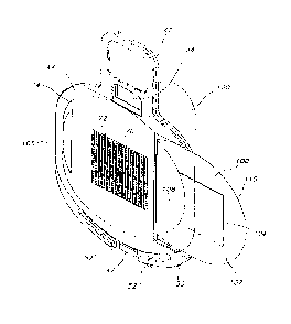
[0009] FIG. 1 is a perspective view of a transdermal permeant delivery
system
showing a first embodiment of a transdermal patch of the present invention
mounted
thereon an embodiment of a disposable substrate.
[0010] FIG. 2 is a perspective view of an exemplary embodiment of an
applicator
of the present invention.
[0011] FIG. 3 is perspective view of the delivery system of Figure 1
releasably
connected to the applicator of Figure 2.
[0012] FIG. 4 is an exploded view of the first embodiment of the
transdermal
patch of Figure 1.
[0013] FIG. 5 is an exploded view of a second embodiment of the transdermal
patch of the present invention.
[0014] FIG. 6 is an exploded view of a third embodiment of the transdermal
patch
of the present invention.
3a
CA 02925191 2016-03-29
100151 FIG. 7 is an exploded view of an embodiment of the substrate of the
transdermal delivery system, showing a ridge extending outwardly from the
upper
substrate surface.
[00161 FIG. 8 is a top elevational view of the substrate of Figure 7.
[0017] FIG. 9 is a bottom elevational view of the substrate of Figure 8.
[00181 FIG.10 is a top elevational view of one embodiment of a filament
array.
[0019] FIG. 11 is an enlarged cross sectional view of the filament array
taken
across line 11 of Figure 10.
100201 FIG. 12 is a perspective view of the filament array of Figure 10.
[0021] FIG. 13 is a cross-sectional view of the filament taken across line
13 of
Figure 12.
[0022] FIGS. 14A-C are schematic views of exemplary balanced filament
arrays.
[0023] FIG. 15 is a schematic, partly sectional view of an exemplary means
for
forming micropores in a tissue membrane.
[0024] FIG. 16 is a schematic view of an electrode assembly of the means
for
forming micropores M a tissue membrane of Figure 15.
[0025] FIG. 17 is a perspective schematic view of the transdermal permeant
delivery system of Figure 1 shown connected to the skin of the subject prior
to the
poration of the skin of the subject.
[0026] FIG. 18 is a perspective schematic view of the transdermal permeant
delivery system showing the transdermal patch being separated from a portion
of the
transdermal permeant delivery system after poration of the subject's skin.
[0027] FIG. 19 is a perspective schematic view of the transdermal patch
positioned in registration with the porated area of the subject's skin.
[0028] FIG. 20 is an exploded view of a fourth embodiment of the
transdermal
patch of the present invention.
[0029] FIG. 21 is an exploded view of a fifth embodiment of the transdermal
patch of the present invention.
[00301 FIG. 22 is a perspective schematic view of the transdermal permeant
delivery system of Figure 21 showing the transdermal patch after being
separated
from a portion of the transdermal permeant delivery system after poration of
the
subject's skin.
4
CA 02925191 2016-03-29
[0031] FIG. 23 is a perspective schematic view of the transdermal permeant
delivery system showing the transdermal patch after the reservoir of the patch
is
folded into registration with the formed micropores.
[0032] FIG. 24 is a perspective schematic view of the transdermal permeant
delivery system showing removable portions of the transdermal permeant
delivery
system being separated from the transdermal patch.
[0033] FIG. 25 shows an exemplary schematic of an applicator circuit.
[0034] FIG. 26 shows an exemplary schematic of an exemplary power circuit
for
the applicator.
[0035] FIG. 27 shows an exemplary schematic of a bias power block diagram.
[0036] FIG. 28 shows an exemplary schematic of a microprocessor block
diagram.
[0037] FIG. 29 shows an exemplary schematic of a vacuum circuit block
diagram.
[0038] FIG. 30 schematically illustrates an exemplary a top level
behavioral flow
diagram of the applicator.
DETAILED DESCRIPTION OF THE INVENTION
[0039] The present invention can be understood more readily by reference to
the
following detailed description, examples, drawing, and claims, and their
previous and
following description. However, before the present devices, systems, and/or
methods
are disclosed and described, it is to be understood that this invention is not
limited to
the specific devices, systems, and/or methods disclosed unless otherwise
specified. It
is also to be understood that the terminology used herein is for the purpose
of
describing particular aspects only and is not intended to be limiting.
[0040] The following description of the invention is provided as an
enabling
teaching of the invention in its best, currently known embodiment. To this
end, those
skilled in the relevant art will recognize and appreciate that many changes
can be
made to the various aspects of the invention described herein, while still
obtaining the
beneficial results of the present invention. It will also be apparent that
some of the
desired benefits of the present invention can be obtained by selecting some of
the
features of the present invention without utilizing other features.
Accordingly, those
who work in the art will recognize that many modifications and adaptations to
the
present invention are possible and can even be desirable in certain
circumstances and
are a part of the present invention. Thus, the following description is
provided as
illustrative of the principles of the present invention and not in limitation
thereof.
CA 02925191 2016-03-29
[0041] As used throughout, the singular forms "a," "an," and "the" include
plural
referents unless the context clearly dictates otherwise. Thus, for example,
reference
to "a filament" can include two or more such filaments unless the context
indicates
otherwise.
100421 Ranges can be expressed herein as from "about" one particular value,
and/or to "about" another particular value. When such a range is expressed,
another
aspect includes from the one particular value and/or to the other particular
value.
Similarly, when values are expressed as approximations, by use of the
antecedent
"about," it will be understood that the particular value forms another aspect.
It will be
further understood that the endpoints of each of the ranges are significant
both in
relation to the other endpoint, and independently of the other endpoint.
100431 As used herein, the terms "optional" or "optionally" mean that the
subsequently described event or circumstance may or may not occur, and that
the
description includes instances where said event or circumstance occurs and
instances
where it does not.
100441 As used herein, a "tissue membrane" can be any one or more epidermal
layers of a subject. For example, in one aspect, the tissue membrane is a skin
layer
that includes the outermost layer of the skin, i.e., the stratum corneum. In
an
alternative aspect, a skin layer can include one or more backing layers of the
epidermis, commonly identified as stratum granulosurn, stratum malpighii, and
stratum germinativum layers. It will be appreciated by one of ordinary skill
in the art
that there is essentially little or no resistance to transport or to
absorption of a
permeant through the backing layers of the epidermis. Therefore, in one aspect
of the
present invention, an at least one formed pathway in a skin layer of a subject
is a
pathway in the stratum come= layer of a subject. Further, as used herein,
"stratum
comeum" refers to the outermost layer of the skin, consisting of from about 15
to
about 20 layers of cells in various stages of drying out. The stratum corneum
provides a barrier to the loss of water from inside the body to the external
environment and from attack from the external environment to the interior of
the
body. Still further, as used herein, "tissue membrane" can refer to an
aggregate of
cells of a particular kind, together with their intercellular substance, that
forms a
structural material. At least one surface of the tissue membrane must be
accessible to
the device. As noted above, the preferred tissue membrane is the skin. Other
tissues
suitable for use with this invention include mucosal tissue and soft organs.
6
CA 02925191 2016-03-29
[0045] As used herein, the term, "subcutaneous fluid" can include, without
limitation, moisture, plasma, blood, one or more proteins, interstitial fluid,
and any
combination thereof. In one aspect, a subcutaneous fluid according to the
instant
invention is a moisture source comprising water.
[0046] As used herein, "poration," "microporation," or any such similar
term
means the formation of a small hole or crevice (subsequently also referred to
as a
"micropore") in or through the tissue or biological membrane, such as skin or
mucous
membrane, or the outer layer of an organism to lessen the barrier properties
of this
biological membrane for the passage of at least one permeant from one side of
the
biological membrane to the other for select purposes. Preferably the hole or
"micropore" so formed is approximately 1-1000 microns in diameter and extends
into
the biological membrane sufficiently to break the barrier properties of the
stratum
comeum without adversely affecting the underlying tissues. It is to be
understood that
the term "micropore" is used in the singular form for simplicity, but that the
device of
the present invention may form multiple artificial openings. Poration could
reduce
the barrier properties of a biological membrane into the body for selected
purposes, or
for certain medical or surgical procedures. For the purposes of this
application,
"poration" and "microporation" are used interchangeably and mean the same
thing.
[0047] A "microporator" or "porator" is a component for a microporation
device
capable of microporation. Examples of a microporator or porator include, but
are not
limited to, a filament capable of conductively delivering thermal energy via
direct
contact to a biological membrane to cause the ablation of some portion of the
membrane deep enough to form a micropore, an optically heated topical
dye/absorber
layer, an electromechanical actuator, a microlancet, an array of microneedles
or
lancets, a sonic energy ablator, a laser ablation system, a high-pressure
fluid jet
puncturer, and the like. As used herein, "microporator" and "porator" are used
interchangeably.
[0048] As used herein, "penetration enhancement" or "permeation
enhancement"
means an increase in the permeability of the biological membrane to a drug,
bio-
active composition, or other chemical molecule, compound, particle or
substance
(also called "permeant"), Le., so as to increase the rate at which the drug,
bio-active
composition, or other chemical molecule, compound or particle permeates the
biological membrane_
7
CA 02925191 2016-03-29
[0049] As used herein, "enhancer," "chemical enhancer," "penetration
enhancer,"
"permeation enhancer," and the like includes all enhancers that increase the
flux of a
permeant, analyte, or other molecule across the biological membrane, and is
limited
only by functionality. In other words, all cell envelope disordering compounds
and
solvents and any other chemical enhancement agents are intended to be
included.
Additionally, all active force enhancer technologies such as the application
of sonic
energy, mechanical suction, pressure, or local deformation of the tissues,
iontophoresis or electroporation are included. One or more enhancer
technologies
may be combined sequentially or simultaneously. For example, a chemical
enhancer
may first be applied to permealize the capillary wall and then an
iontophoretic or
sonic energy field may be applied to actively drive a permeant into those
tissues
surrounding and comprising the capillary bed.
[0050] As used herein, "transdermal" means passage of a permeant into and
through the biological membrane.
[0051] As used herein, the term "permeant," "drug," "permeant composition,"
or
"pharmacologically active agent" or any other similar term are used
interchangeably
to refer to any chemical or biological material or compound suitable for
transdermal
administration by the methods previously known in the art and/or by the
methods
taught in the present invention, that induces a desired biological or
pharmacological
effect, which may include but is not limited to (1) having a prophylactic
effect on the
organism and preventing an undesired biological effect such as an infection,
(2)
alleviating a condition caused by a disease, for example, alleviating pain or
inflammation, and/or (3) either alleviating, reducing, or completely
eliminating the
disease from the organism. The effect may be local, such as providing for a
local
anesthetic effect, or it may be systemic. Such substances include broad
classes of
compounds normally, delivered into the body, including through body surfaces
and
membranes, including skin. In general, for example and not meant to be
limiting,
such substances can include any drug, chemical, or biological material that
induces a
desired biological or pharmacological effect. To this end, in one aspect, the
permeant
can be a small molecule agent. In another aspect, the permeant can be a
macromolecular agent. In general, and without limitation, exemplary permeant
include, but are not limited to, anti-infectives such as antibiotics and
antiviral agents;
analgesics and analgesic combinations; anorexics; antihelininthics;
antiarthritics;
antiasthmatic agents; anticoagulant; anticonvulsants; antidepressants;
antidiabetic
8
CA 02925191 2016-03-29
agents; antidiarrheals; antihistamines; antiinflammatory agents; antimigraine
preparations; antinauseants; antineoplastics; antiparkinsonism drugs;
antipruritics;
antipsychotics; antipyretics; antispasmodics; anticholinergics;
sympathomimetics;
xanthine derivatives; cardiovascular preparations including potassium and
calcium
channel blockers, beta-blockers, alpha-blockers, and antiarrhythmics;
antihypertensives; diuretics and antidiuretics; vasodilators including general
coronary,
peripheral, and cerebral; central nervous system stimulants; vasoconstrictors;
cough
and cold preparations, including decongestants; hormones such as estradiol and
other
steroids, including corticosteroids; hypnotics; immunosuppressives; muscle
relaxants;
parasympatholytics; psychostimulants; sedatives; and tranquilizers.
[0052] The devices and methods of the instant invention can also be used to
transdermally deliver peptides, polypeptides, proteins, or other
macromolecules
known to be difficult to convey across the skin with existing conventional
techniques
because of their size. These macromolecular substances typically have a
molecular
weight of at least about 300 Daltons, and more typically, in the range of
about 300 to
40,000 Daltons. Examples of polypeptides and proteins which may be delivered
in
accordance with the present invention include, without limitation, antibodies,
LHRH,
LIERH analogs (such as goserelin, leuprolide, buserelirt, ttiptorelin,
gonadorelin,
napharelin and leuprolide), insulinotropin, calcitonin,
octreotide, endorphin, TRH, NT-36 (chemical name: N-U(s)-4-oxo-2-azetidinyl]-
carbonyl]-L-histidyl-L-prolinamide), liprecin, pituitary hormones (e.g., HGH,
HMG,
HCG, desmopressin acetate, etc.), follicle luteoids, alpha-ANF, growth factor
such as
releasing factor (GFRF), beta-MSH, OH, somatostatin, bradykinin, somatotropin,
platelet-derived growth factor, asparaginase, bleomycin sulfate, chymopapain,
cholecystoldnin, chorionic gonadotropin, corticotropin (ACTH), erythropoietin,
epoprostenol (platelet aggregation inhibitor), glucagon, hirudin and hirudin
analogs
such as hirulog, hyaluronidase, interleukin-2, menotropins (urofollitropin
(FSH) and
LH), oxytocin, streptokinase, tissue plasminogen activator, urokinase,
vasopressin,
desmopressin, ACTH analogs, ANP, ANP clearance inhibitors, angiotensin IT
antagonists, antidiuretic hormone agonists, antidiuretic hormone antagonists,
bradyldnin antagonists, CD4, ceredase, CSI's, enkephalins, FAB fragments, IgE
peptide suppressors, IGF-1, neurotrophic factors, colony stimulating factors,
parathyroid hormone and agonists, parathyroid hormone antagonists,
prostaglandin
antagonists, cytokines, lympholcines, pentigetide, protein C, protein S, renin
9
CA 02925191 2016-03-29
inhibitors, thymosin alpha-1, thrombolytics, TNF, GCSF, EPO, PTH, heparin
having
a molecular weight from 3000 to 12,000 Daltons, vaccines, vasopressin
antagonist
analogs, interferon-alpha, -beta, and -gamma, alpha-I antitrypsin
(recombinant), and
TGF-beta genes; peptides; polypeptides; proteins; oligonucleotides; nucleic
acids; and
polysaccharides.
[0053] Further, as used herein, "peptide", means peptides of any length and
includes proteins. The terms "polypeptide" and "ofigopeptide" are used herein
without any particular intended size limitation, unless a particular size is
otherwise
stated. Exemplary peptides that can be utilized include, without limitation,
oxytocin,
vasopressin, adrenocorticotrophic hormone, epidermal growth factor, prolactin,
luliberin or luteinising hormone releasing hormone, growth hormone, growth
hormone releasing factor, insulin, somatostatin, glucagon, interferon,
gastrin,
tetragastrin, pentagastrin, urogastroine, secretin, calcitonin, enkephalins,
endorphins,
angiotensins, renin, bradykinin, bacitracins, polymixins, colistins, tymcidin,
gramicidines, and synthetic analogues, modifications and pharmacologically
active
fragments thereof; monoclonal antibodies and soluble vaccines. It is
contemplated
that the only limitation to the peptide or protein drug which may be utilized
is one of
functionality.
100541 Examples of peptide and protein drugs that contain one or more amino
groups include, without limitation, anti-cancer agents, antibiotics, anti-
emetic agents,
antiviral agents, anti-inflammatory and analgesic agents, anesthetic agents,
anti-
ulceratives, agents for treating hypertension, agents for treating
hypercalcemia, agents
for treating hyperlipidemia, etc., each of which has at least one primary,
secondary or
tertiary amine group in the molecule, preferably, peptides, proteins or
enzymes such
as insulin, calcitonin, growth hormone, granulocyte colony-stimulating
factor(G-
CSF), erythropoietin (EPO), bone morphogenic protein (BMP), interferon,
interleukin, platelet derived growth factor (PDGF), vascular endothelial
growth factor
(VEGF), fibroblast growth factor (F'GF), nerve growth factor (NGF), urokinase,
etc.
can be mentioned. Further examples of protein drugs include, without
limitation,
insulin, alpha-, beta-, and gamma-interferon, human growth hormone, alpha- and
beta- 1-transforming growth factor, granulocyte colony stimulating factor (G-
CSF),
granulocyte macrophage colony stimulating factor (G-MCSF), parathyroid hormone
(PTH), human or salmon calcitonin, glucagon, somatostatin, vasoactive
intestinal
peptide (VIP), and LHRH analogs.
CA 02925191 2016-03-29
100551 As used herein, an "effective" amount of a pharmacologically active
agent
means an amount sufficient to provide the desired local or systemic effect and
performance at a reasonable benefit/risk ratio attending any medical
treatment. An
"effective" amount of a permeation or chemical enhancer as used herein means
an
amount selected so as to provide the desired increase in biological membrane
permeability, the desired depth of penetration, rate of administration, and
amount of
drug delivered.
100561 Embodiments of the present invention are described below with
reference
to block diagrams and flowchart illustrations of methods, apparatuses (i.e.,
systems)
and computer program products according to an embodiment of the invention. It
will
be understood that each block of the block diagrams and flowchart
illustrations, and
combinations of blocks in the block diagrams and flowchart illustrations,
respectively,
can be implemented by computer program instructions. These computer program
instructions may be loaded onto a general purpose computer, special purpose
computer, or other programmable data processing apparatus to produce a
machine,
such that the instructions which execute on the computer or other programmable
data
processing apparatus create a means for implementing the functions specified
in the
flowchart block or blocks.
[0057] These computer program instructions may also be stored in a computer-
readable memory that can direct a computer or other programmable data
processing
apparatus to function in a particular manner, such that the instructions
stored in the
computer-readable memory produce an article of manufacture including computer-
readable instructions for implementing the function specified in the flowchart
block or
blocks. The computer program instructions may also be loaded onto a computer
or
other programmable data processing apparatus to cause a series of operational
steps to
be performed on the computer or other programmable apparatus to produce a
computer-implemented process such that the instructions that execute on the
computer
or other programmable apparatus provide steps for implementing the functions
specified in the flowchart block or blocks.
[0058] Accordingly, blocks of the block diagrams and flowchart
illustrations
support combinations of means for performing the specified functions,
combinations
of steps for performing the specified functions and program instruction means
for
performing the specified functions. It will also be understood that each block
of the
block diagrams and flowchart illustrations, and combinations of blocks in the
block
11
CA 02925191 2016-03-29
diagrams and flowchart illustrations, can be implemented by special purpose
hardware-based computer systems that perform the specified functions or steps,
or
combinations of special purpose hardware and computer instructions.
[0059] Referring to the figures, the present invention for a transdermal
penneant
delivery system comprises a system and method for painlessly creating
microscopic
holes, i.e., micropores, from about 1 to about 1000 microns in diameter in the
biological membrane of a subject, such as, for example, and not meant to be
limiting,
the stratum comeum of human skin. The system allows for a rapid and painless
method of eliminating the barrier function of the stratum comeum to facilitate
the
transcutaneous transport of therapeutic substances into the body via the
formed
micropores when applied topically to the poration site.
[0060] In one embodiment, the transdermal permeant delivery system 10
comprises an applicator 20, a substrate 40 that comprises a portion of a means
for
forming at least one micropore, and a registerable patch 100 that is
configured to
contain at least one permeant. In one aspect, the applicator 20 comprises a
body 22
that defines an interior cavity 24 and a portion of the means for forming at
least one
micropore. In this exemplary aspect, the portion of the means for forming at
least one
micropore of the applicator 20 can comprise a controller 26 comprising driving
electronics such as, for example, an electrical circuit board and a power
source, such
as, for example a battery. In this aspect, the controller 26 is positioned
within the
interior cavity of the body. In an exemplary aspect, the controller is
configured to
provide a stimulus to the means for fbrming the at least one micropore that is
positioned therein the substrate 40 to initiate formation of the at least one
micropore
upon user command. In alternative aspects, the stimulus can comprise an
electrical
driving current, such as, for example and not meant to be limiting, a pulsed
electrical
current, a RF pulse, and the like, when an actuator button 28 is actuated by a
user of
the system. Optionally, the controller 26 is configured to provide a thermal
pulse
when the actuator button is pressed.
[0061] In a further aspect, the applicator 20 comprises an interface 30
that is
configured for securely and releasably mounting the substrate 40 thereto. The
applicator interface can comprise an anode 31 and a cathode 32 that are in
electrical
communication with respective portions of the means for forming the at least
one
micropore when the substrate is mounted to the interface. In one aspect, the
anode
and cathode extend outwardly from the interface 30 of the applicator.
Optionally, the
12
CA 02925191 2016-03-29
anode and the cathode can be pins that extend from the interface of the
applicator to
from two exposed electrodes.
[0062] In another aspect, the applicator 20 can further comprise a source
of
vacuum 33, such as, for example, a vacuum pump. In this aspect, it is
contemplated
that the interface 30 defines a first port 34 that is in communication with
the source of
vacuum. Further, the interface 30 of the applicator 20 can comprise a gasket
36
mounted about the first port of the interface. Optionally, the interface can
define a
second port 35 that is in communication with a vacuum sensor 37. In this
aspect, it is
contemplated that the respective first and second ports are surrounded by the
gasket.
[0063] The substrate 40 of the system can comprise an upper substrate
surface 42,
a lower substrate surface 44 and a defined poration area 46. In one aspect,
the
poration area defines an area on the upper substrate surface 42 upon which at
least a
portion of a means for forming at least one micropore is positioned. Thus, in
operation, the micropores formed by the system of the present invention will
be
confined to those portions of the tissue membrane that underlie the poration
area of
the substrate.
[0064] In one aspect, the substrate 40 can have at least one male tab 46
that
extends outwardly from a peripheral edge portion 50 of the substrate. Further,
a
portion of the peripheral edge of the substrate can comprise at least one bias
element
52. In one exemplary aspect, the at least one bias element 52 comprises at
least one
partial leaf spring member 52', 52" that is positioned to articulate generally
within the
plane of the substrate. Optionally, the at least one male tab can be
positioned on the
peripheral edge of the substrate such that is positioned generally between a
pair of
bias elements. In a further aspect, the substrate defines an opening 54 that
is
positioned generally opposite to the at least one bias element and,
optionally,
generally opposite to the at least one male tab 46. In this aspect, the
interface 30 of
the applicator 20 comprises a lip 38 and at least one slot 39 that are
configured to
operatively engage the respective at least one bias element and the at least
one male
tab of the substrate. In a further aspect, the interface 30 comprises a male
finger 41
that extends outwardly from the face of the interface. In this aspect, the
male finger
can be positioned generally opposite to the at least one slot 39. One skilled
in the art
will appreciate that the cooperative relationship between the at least one
bias element
52, the at least one male tab 46, and the opening 54 of the substrate 40 and
the lip 38,
13
CA 02925191 2016-03-29
the at least one slot 39, and the male finger 41 of the interface facilitates
a user's
ability to easily mount and remove the substrate from the interface of the
applicator.
[0065] In a further aspect, the substrate 40 defines a conduit 56 that
extends
between the lower and upper substrate surfaces. In this aspect, one open end
58 of the
conduit is defined on the poration area 46 that is formed on the upper
substrate
surface 42 of the substrate. In another aspect, the substrate 40 defines at
least one
channel 60 on the upper substrate surface 42. It is contemplated that the at
least one
channel will be formed therein the poration area of the substrate. In this
aspect, the at
least one channel 60 is in fluid communication with the conduit. When the
substrate
40 is mounted to the interface 30, the open end 59 of the conduit defined on
the lower
substrate surface 44 is configured to be positioned in fluid communication
with the
port 34 of the interface. In one operational aspect and as one skilled in the
art will
appreciate, the gasket 36 helps to form a fluid tight seal between the
respective first
and second ports of the applicator 20 and the conduit 56 of the substrate when
the
source of vacuum 33 is actuated.
[0066] Optionally, the substrate 40 can comprises a ridge 41 defined on the
upper
substrate surface 42 that, in one embodiment, extends generally outwardly from
the
upper substrate surface. In one aspect, the ridge extends peripherally about
at least a
portion of the poration area of the substrate. In a further exemplary aspect,
the ridge
is continuous and substantially surrounds the poration area. In use, the
exemplary
ridge can act as a sealing member formed between the biological membrane and
the
substrate when the source of vacuum is actuated and communicated to the
poration
area via the conduit and the channels. Thus, the ridge can aid in minimizing
the
amount of vacuum required to draw the biological membrane into substantial
conformal contact with the means for forming at least one micropore that is
positioned therein the poration area.
[0067] In a further aspect, the substrate 40 can optionally define a female
depression 48 on a portion of the upper substrate surface that extends from a
portion
of the peripheral edge of the substrate inwardly toward the poration area of
the
substrate. In this aspect, the edges of the female depression in the upper
substrate
surface can form the ridge 41. Optionally, at least a portion of the ridge 41
of the
female depression 48 can be spaced a predetermined distance from the poration
area
46 of the substrate. In another aspect, the female depression can be
substantially
planar.
14
CA 02925191 2016-03-29
[0068] In alternative aspects, the means for forrning at least one
micropore
comprises at least one filament that can comprise, for example and not meant
to be
limiting, a wire conductor, a deposited conductive material, a machined
conductive
material, a laser conductive material, an adhesive foil, an electroplated
material, a
screen-printed material, and etched conductive material, and the like. In a
further
aspect the at least one filament can comprise a filament array having a
plurality of
filaments. Various methodologies for forming filament arrays suitable for use
in the
system of the present invention are described in U.S. Pat. Nos. 6,692,456 and
7,141,034 to Eppstein, etal..
[0069] Optionally, the means for forming at least one micropore can
comprise, for
example and not meant to be limiting, a filament capable of conductively
delivering
thermal energy via direct contact to the tissue biological membrane to cause
the
ablation of some portion of that membrane deep enough to form the micropore, a
probe element capable of delivering electrical energy via direct contact to a
tissue
membrane to cause ablation of some portion of said membrane deep enough to
form
the micropore, an electro-mechanical applicator, a microlancet, an array of
micro-
needles or lancets, a sonic energy ablator, a laser ablation system, and a
high-pressure
fluid jet puncturer as described in U.S. Pat. Nos. 5,885,211 to Eppstein,
etal.,
6,527,716 to Eppstein, et al., and pending U.S. Published Applications Nos.
11/081,448.
[0070] In a further exemplary aspect and as shown in Figures 10-14C, the
means
for forming at least one micropore comprises a filament array 70 that has a
plurality
of filaments 72 formed therein. In this aspect, each filament 72 is configured
for
conductively delivering thermal energy via direct contact to the tissue
biological
membrane to cause the ablation of some portion of that membrane deep enough to
form the micropore.
[0071] In one exemplary aspect, the filament array 70 is mounted to a
portion of
the upper substrate surface 42. Optionally, an adhesive layer 73 can be
mounted to a
portion of the upper substrate surface and is configured to allow for the
mounting of
the electrically isolated portions of the filament array, i.e, the adhesive
layer 73 is
interposed between the upper substrate surface and portions of the
electrically isolated
portions of the filament array. In this aspect, it is contemplated that the
adhesive layer
73 defines a pair of openings that are configured to allow the passage of the
anode 31
CA 02925191 2016-03-29
and cathode 32 when the substrate is connected to the applicator. In
operation, the
adhesive layer 73, is connected to a portion of the bottom surface of the
respective
electrically isolated portions of the filament array and the portion of the
upper
substrate surface. This connection is configured to minimize possible vacuum
loss
through the ports 45 in the substrate that extend from the lower substrate
surface
(which are described in more detail below) when vacuum is supplied to the
substrate.
[0072] In another aspect, the substrate 40 can further comprise a backing
74 that
is configured to mount to and overlie at least a portion of the top surface 71
of the
filament array such that a portion of the filament array in the poration area
46 is
exposed. In this aspect, the filaments 72 are exposed such that they can be
brought
into intimate contact with body tissue. In another aspect, the backing 74 can
act to
electrically isolate portions of the filament array. In a further aspect, the
substrate can
comprise an adhesive layer 76 that is disposed between the backing and the
filament
array.
[0073] In another exemplary aspect, the filament array is substantially
enclosed in
the substrate. One would appreciate however that in this aspect, the portion
of the
filament array in the poration area is exposed. As noted above, the filaments
are
exposed such that they can be brought into intimate contact with body tissue.
[0074] In a further aspect, the filament array 70 can be, for example and
not
meant to be limiting, a bi-clad foil 80 comprising a conductive layer 82 and a
resistive
layer 84. In one aspect, the materials that the bi-clad foil is formed from
can
comprise, for example but not limited to: conductive material such as
aluminum,
copper, silver, gold, carbon, bronze, false bronze, or the like, and resistive
material
such as titanium, titanium nitride, tantalum, tantalum nitride, chromium, a
carbon
compound, tungsten, manganese, nichrom, nickel, platinum, evanohm,
polysilicon,
stainless steel, or the like. In one exemplary aspect, the bi-clad foil 80
comprises a
conductive layer of copper and an underlying resistive layer of stainless
steel.
[0075] In one exemplary aspect, the filament array 70 can be formed by a
photochemical wet etching process in which an etch resist, for example and not
meant
to be limiting, a positive or negative acting liquid, dryfilm or powder
resist, is
selectively applied to the bi-clad foil via conventional methods, such as, for
example,
liquid coating, lamination, electrodeposition, and the like. The resist-coated
foil is
then exposed to UV light through a negative or positive photo-tool, creating
the
16
CA 02925191 2016-03-29
desired pattern. Exposed areas are cross-linked and etch-resistant, whereas
non-
exposed areas can be removed to expose the foil for etching.
[0076] In one example, the etching is a two-step process. In the first
step, for an
exemplary stainless steel/copper hi-clad foil, both metals of the bi-clad foil
are etched
simultaneously. In this aspect, all features on the stainless steel side of
the bi-clad foil
are etched to specification and features on the copper side are etched
partially. The
second etching step etches the conductive copper traces to specification and
substantially removes all of the copper residues from the backside of the
filaments.
At the completion of the second etching step, the filaments are formed
substantially of
the stainless steel material, which are highly resistant. In one aspect, the
etching
process results in the removal of all of the material from between the
filaments, and
can optionally produce some undercutting of the relatively wide feeder traces.
[0077] Optionally, an optical machining station, or other suitable
micromachining
techniques such as diamond milling, electron beam etching, or the like,
selectively
removes portions of the conductive layers and resistive layer of the bi-clad
foil to
create a pattern of feeder traces and filaments. The use of a laser may be
advantageous in some applications as it only requires one step and can be
designed to
form the programmed patterns rapidly in the resistive layer, as this layer is
typically
thinner than the conductive layer, and/or more photo-absorbent. Optionally, an
adhesive film can be applied to any layer, and a laser machining station used
to
remove material to form a mask for etching. In another aspect, an adhesive
film can
be applied to the bi-clad foil and a laser machining station is used to remove
material
to form a mask for etching the desired pattern in the bi-clad foil below the
exposed
portions of the mask.
[0078] In a further aspect, and without limitation, the bi-clad foil 80 can
be
produced by a cold-rolling, low-pressure process, by reduction-cold rolling,
by
reduction-hot rolling, explosion-bonding, plating, and the like. The bi-clad
foil can be
between about 10 pm to about 300 pm in a thickness (t) dimension, including
additional nominal thicknesses of 20, 30, 40, 50 ,60 ,70,.80, 90, 100, 110,
120, 130,
140, 150, 160, 170, 180, 190, 200, 210, 220, 230, 240, 250, 260, 270, 280, and
290
itm, with 105 pm being one preferred thickness. In one aspect, it is
contemplated that
the filaments are substantially uniform. Optionally, the filaments can be non-
uniform.
Further, it is contemplated that the filaments have a substantially similar
thermal
mass. In one exemplary aspect, the width (w) of each filament 72, transverse
to the
17
CA 02925191 2016-03-29
longitudinal axis of the filament, can range between about 30 to 150 Am,
including
additional nominal widths of 35, 40, 35, 50, 55, 65, 70, 75, 80, 85, 90, 95,
100, 105,
110, 115, 120, 125, 130, 135, 140, and 145 Am, with a range of between about
45 and
55 jam or between 115 and 125 Am being preferred. Similarly, in another
exemplary
aspect, each filament 74 has a length (/) extending along the longitudinal
axis of the
filament, of between about 200 to 700 ttm, with additional lengths of 250,
300, 350,
400, 450, 500, 550, 600, and 650 pm, with 500 p.m being preferred.
[0079] Optionally, the layer of stainless steel can comprise between about
5 to
about 25 percent of the thickness of the hi-clad foil, including additional
amounts as
6%, 7%, 8%, 9%, 10%, 11%, 12%, 13%, 14%, 15%, 16%, 17%, 18%, 19%, 20%,
21%, 22%, 23%, and 24%, and including any range of thickness percentages
derived
from these values.
[0080] In a further aspect and referring to Figures 14A-14C, the filament
array 70
comprises means for distributing energy to the filaments of the filament
array. In one
exemplary aspect, the means for distributing energy to the filaments comprises
at least
one electrical bank 86. Optionally, the at least one electrical bank comprises
a
plurality of electrical banks 86', 86". In this aspect, each electrical bank
has
associated filaments 72. In one aspect of the means for distributing energy,
the
poration area 46 has a first portion and an opposite and/or mirrored second
portion in
which portions of each respective electrical bank are positioned in both the
first and
second portions of the poration area. In this example, the banks are
geometrically
shaped so that filaments of one bank are present in both "halves" or portions
of the
active poration area. It will be appreciated that alternative geometrically
shaped
banks 86 can be used such that the respective banks are distributed between
respective
portions of the active poration area. One skilled in the art will note that
the use of
such electrical banks makes the filament array 70 less sensitive to small
differences in
the individual filament composition and dimensions
[0081] In another aspect, the substrate 40 defines a pair of ports 45 in
the lower
substrate surface 44 that expose respective electrically isolated portions of
the
filament array. In one aspect, the ports 45 are configured to accept the anode
31 and
cathode 32 of the applicator 20 when the substrate is mounted to the interface
30 of
the applicator such that the anode and cathode are in contact with the
respective
electrically isolated portion of the filament array. Thus, the filament array
70 can be
placed in electrical communication with the applicator 20 when the substrate
40 is
18
CA 02925191 2016-03-29
received onto the interface 30 so that electrical energy can be passed from
the
applicator, via the anode and cathode and the respective banks 86, to each of
the
filaments 72 of the filament array 70.
[0082] In a further exemplary aspect and as shown in Figures 15 and 16, the
means for forming at least one micropore comprises a plurality of paired
electrodes.
In this aspect, each pair of electrodes are configured for delivering
electrical energy
via direct contact to the tissue biological membrane to cause the electrical
ablation of
some portion of that membrane deep enough to form the micropore. For example,
U.S. Patent Nos. 5,885,211, 6,148,232, 6,615,079, and 6,711,435,
describe methods and
devices for applying electrical energy between two or more of a plurality of
electrodes, which are applied to a subject's skin, in order to cause ablation
of the
tissue in an area between the respective electrodes.
[0083] In one exemplary aspect, the means for forming at least one
micropore
further comprises a control unit 90 that is attachable to the plurality of
electrodes,
which is preferably fixed to a suitable area of a subject's skin. The means
for forming
at least one micropore can administer an active substance through the normally
substantially-impermeable stratum comeum layer of the skin by passing a
controlled
electric current between the plurality of electrodes, which ablates the
stratum comeum
and generates micro-channels through which the substance can pass.
[0084] In one aspect, when means for forming at least one micropore drives
current through the stratum comeum, the affected tissue is heated resistively,
so that
the tissue is ablated by the total energy dissipated therein when a sufficient
quantity of
energy has passed therethrough in a short time period. The ablation creates
the
desired micropores in the form of micro-channels in the tissue. In an
additional
aspect, the application of a current to a small area of the skin leads to
formation of
micro-channels that can be sized to allow for even large molecules to pass
relatively
freely, without the necessity of ionizing or polarizing the molecules, and
without
causing pain or substantial trauma to the dermis and epidermal tissue
underlying the
stratum comeum.
[0085] In one aspect, the control unit 90 comprises a switching unit 91, a
battery
92 (such as a lithium coin cell battery), and an optional user-interface
comprising
buttons 93 and a sensible signal generator 94, which may comprise a display
and/or a
19
CA 02925191 2016-03-29
buzzer. In one exemplified aspect, the buttons 93 initialize and terminate
delivery of
the active substance.
[0086] Figure 16 shows an array 95 of electrodes 96 that comprises sixteen
electrodes. It is of course contemplated that the array might be smaller,
while in
others the array might be larger, for example 50x50 or even more, so as to
enable a
greater amount of the active substance to be delivered_ In the illustrated
aspect, the
electrodes 96 in this embodiment are preferably organized into eight electrode
pairs
97, such that most of the charge leaving one electrode in a pair goes to the
other
electrode in that respective pair and generally does not go to electrodes in
an adjacent
pair of electrodes. In one aspect, electrode pairs 97 can be densely packed in
order to
maximize the transdermal transfer rate. For example and not meant to be
limiting, the
density may range from 4-100 electrode sets/cm2_ In a further aspect, each
electrode
pair typically generates at least one micro-channel before a threshold of
current or
total charge transfer is passed, in response to which, the switching unit 91
causes
current to the electrode pair to be terminated or reduced.
[0087] Preferably, the spacing between electrodes in each electrode pair is
smaller
than about 0.1 min, although, for example and not meant to be limiting, it may
range
from between about 0.1 mm to about 0.3 mm. Generally, the distance between the
respective electrodes of an electrode pair is set such that a desired electric
field
penetration depth is achieved. In one example, the desired electric field
penetration
depth is substantially of the same magnitude as the thickness of the stratum
comeum,
so that the current mostly does not enter epidermal tissue underlying the
stratum
c,omeum. In this exemplary aspect, maintaining the electrode spacing between
about
0.01 mm and about 0.1 mm, including additional spacing of 0.02, 0.03, 0.04,
0.05,
0.06, 0.07, 0.08, and 0.09 mm, generates micro-channels therein the stratum
comemn
while substantially reducing damage, sensation and/or pain in the innervated
dermis
and in the epidermal tissue below the stratum corneum.
[0088] At any point in the skin in a vicinity of two electrodes placed
thereon, the
electric field generated between the electrodes can be viewed as having
fundamentally
two components: a component perpendicular to the skin, which generally causes
current flow perpendicular to the skin; and a lateral component, which
generally
causes current flow parallel to the skin surface. An electric field at the
base of the
stratum corneurn having a relatively large lateral component generates current
flow
predominantly in the stratum comeum, with relatively little current flow into
the
CA 02925191 2016-03-29
underlying epidermal tissue. Thus, in one aspect, tissue ablation can be
restricted to
occur mostly in the stratum comeum However, it is contemplated that the means
for
forming at least one micropore can be used to form micropores, i.e., micro-
channels
in this example, that extend to a desired penetration depth below the stratum
corneum
layer.
10089] In a further aspect, the electrode array is disconnected from the
switching
unit or power source at substantially the same time as ablation of the stratum
comeum
is completed. In one aspect, the switching unit 91 can monitor current flow to
the
electrodes 96 and selectively terminates the flow to one or more electrodes
upon a
determination that ablation of the underling tissue has occurred. In this
exemplary
aspect, the current flow to all of the electrodes in the array is
substantially terminated
upon a determination by the switching unit 91 that the underlying tissue under
the
electrode array has been ablated.
100901 In yet another aspect, the substrate 40 can dRfine at least one
female
depression 140 that is defined on the lower substrate surface 44. In this
aspect, the at
least one of female depression is configured to cooperate with a series of
depressible
elements 142 mounted on the interface 30 of the applicator 20. The depressible
elements are in communication with the controller board of the applicator. In
one
exemplary aspect, there are three depressible elements such that, in an
exemplary
operation, if a substrate having two female depressions is mounted to the
interface,
only one of the depressible elements of the applicator would be depressed. In
this
example, the depression of only one of the three depressible elements would
electrically communicate to the controller board the respective size of the
poration
area of the substrate that is mounted on the interface. One would appreciate
that, in
this example, selective depression of the depressible elements can communicate
varying sizes of the poration area of the respective substrate.
[0091] In a further aspect of the invention, the delivery system 10 further
comprises a first release liner 110 that has a top surface 112 and an opposed
bottom
surface 114. In one aspect, at least a portion of the bottom surface of the
first release
liner is connected to a portion of the upper substrate surface 42. In another
aspect, the
system can comprise an adhesive layer 116 positioned therebetween the upper
surface
of the substrate 40 and the bottom surface 114 of the first release liner to
connect the
substrate 40 to the first release liner 110. In one aspect, an edge portion of
first
release liner is spaced a predetermined distance from the poration area of the
21
CA 02925191 2016-03-29
substrate. Optionally, the edge portion of the first release liner is
positioned
substantially adjacent to a portion of the ridge formed on the upper substrate
surface.
In this aspect, if the substrate defines the female depression in the upper
substrate
surface, the adhesive layer can be positioned adjacent a portion of the ridge
of the
female depression and the edge portion of the first release liner can also be
positioned
adjacent the portion of the ridge. In a further aspect, the patch 100 is
selectively
removable from the top surface 112 of the first release liner.
[0092] In a further aspect, the patch 100 can comprise a backing layer 102
and a
reservoir 104 mounted to a portion of the backing layer. The reservoir 104 is
configured for releaseably containing the at least one permeant for delivery
into the
tissue membrane of the subject via the formed micropores. In one aspect, the
reservoir 104 is mounted on a portion of a lower surface 106 of the backing
layer 102.
As shown in the figures, in a connected position, a first portion 107 of the
backing
layer 102 is releaseably mounted to the top surface 112 of the first release
liner in
spaced registration with the poration area 76 of the substrate 40. Further, in
the
connected position, a second portion 108 of the backing layer 102 is folded
back into
a folded position. As one skilled in the art will appreciate, the lower
surface 106 of
the second portion 108 of the backing layer faces outwardly away from the
upper
substrate surface 42 of the substrate in the folded position.
[0093] In a further aspect, the patch 100 can comprise a skin adhesive
layer 103
disposed on at least a portion of the lower surface 106 of the backing layer
of the
patch such that the patch can be selectively releasably mounted to the tissue
membrane of the subject. In another aspect, the delivery system 10 can further
comprise a second release liner 120 that is releaseably mountable to a portion
of the
skin adhesive layer 103 that is disposed thereon the second portion of the
backing
layer. Optionally, an adhesive anchor layer 105, such as, for example, double-
sided
adhesive and the like, can be mounted onto a portion of the filament array
backing
layer 74. In this aspect, the second release liner can be releaseably mounted
to a
portion of the skin adhesive layer 103 and the adhesive anchor layer.
[0094] The second release liner 120 provides a releasable cover that
protects the
otherwise exposed portion of the skin adhesive layer during storage. In this
aspect, it
is contemplated that the force required to remove the second release liner 120
from
the skin adhesive layer 103 would be less than the force required to remove
the first
portion 107 of the backing layer 102 from the top surface of the first release
liner.
22
CA 02925191 2016-03-29
Thus, the second release liner 120 can be removed from the patch 100 to expose
the
folded over portion of the skin adhesive layer 103 without separating the
patch 100
from the top surface 112 of the first release liner 110. In one aspect, a slit
122 can be
defined therein a portion of the second release liner 120 so that the second
release
liner can be readily grasped and removed without imparting undo force to the
underlying structure, i.e., without separating the patch 100 from the top
surface 112 of
the first release liner 110.
[0095] In a further aspect, the top surface 112 of the first release liner
can have a
release coating disposed thereon. The release coating can be any conventional
release
coating comprising, for example and not meant to be limiting, silicone,
platinum-
catalyzed silicone, fluorosilicone, perfluorocarbon-based polymer, and the
like.
[0096] In the connected position, in another aspect, the first portion 107
of the
backing layer 102 is positioned in folded registration with the porafion area
76 of the
substrate 40. As exemplified in the figures, the fold can be spaced a
predetermined
distance from the poration area. In one aspect, an edge of the reservoir 104
can be
spaced substantially adjacent to the fold. Optionally, the reservoir can be
spaced a
predetermined distance from the fold. In the exemplified aspects, the
reservoir is
positioned in registration with the fold.
[0097] Referring now to Figures 4-6, a portion of the first portion 107 of
the
backing layer 102 underlies the second portion 108 of the backing layer in the
connected position. In a further aspect, the system 10 can comprise a support
member
130 that is positioned on portions of the upper surface 105 of the backing
layer 102.
In one aspect, the support member 130 has an edge surface 132. Further, in yet
another aspect, the support member 130 can be releaseably mounted onto
portions of
the upper surface 105 of the backing layer such that, in the connected
position, the
support member 130 is positioned between the upper surface 105 of the second
portion 108 of the backing layer 102 and a portion of the upper surface 105 of
the first
portion 107 of the backing layer 102.
[0098] In one exemplified aspect, the edge surface 132 of the support
member
130 is positioned adjacent to the fold. In another aspect, the support member
can
comprise a substantially planar member. In this aspect, the support member can
also
comprise a portion that is folded back onto itself to form the edge surface.
Optionally, the portion that is folded back onto itself can be secured into
position with
an adhesive.
23
CA 02925191 2016-03-29
[0099] In yet another exemplary aspect, the support member 130 can define
at
least one hole 136 that extends therethough the support member. In this
aspect, the
support member can be selectively secured relative to the backing layer by
heat
welding overlapping portions of the backing layer that are in registration
with the at
least one hole. In operation, when the patch is folded over onto the
microporated
tissue membrane, the heat welded "tacks" would break apart to allow for the
registration of the reservoir of the patch with the microporated portion of
the tissue
membrane.
[00100] In a further exemplary aspect, the support member can define a pair of
opposed tabs that are configured to extend beyond the outer edge of the
backing layer.
In one aspect, the tabs are secured to the upper substrate surface by the use
of tape or
the like that overlies the respective tabs and is secured to portions of the
upper
substrate surface. In one aspect, the portion of the tape that overlies the
respective
tabs can be non-adhesive such that the respective tabs are not adhesively
connected to
the overlying tape.
[00101] In another exemplary aspect, the support member 130 can further
comprise
an adhesive tape 134 that is mounted therebetween a portion of the overlapping
first
and second portions of the backing layer 102. In this example, the tape can be
positioned between the upper surface 105 of the second portion 108 of the
backing
layer and a portion of the upper surface 105 of the first portion 107 of the
backing
layer in the connected position. In operation, when the patch 100 is folded
over onto
the microporated portion of the tissue membrane, the adhesive tape 134 is
configured
to release from the backing layer 102.
[00102] Referring to Figure 20, an alternative embodiment of the delivery
system
is schematically illustrated. In this aspect, the delivery system 10 further
comprises a
first release liner 110 that has a top surface 112 and an opposed bottom
surface 114.
In one aspect, at least a portion of the bottom surface of the first release
liner is
connected to a portion of the backing 74. In another aspect, the system can
comprise
an adhesive layer 116 positioned therebetween the upper surface of the backing
and
the bottom surface 114 of the first release liner to connect the backing 74 to
the first
release liner 110. In one aspect, an edge portion of first release liner is
spaced a
predetermined distance from the poration area of the substrate. In a farther
aspect, the
patch 100 is selectively removable from the top surface 112 of the first
release liner.
24
CA 02925191 2016-03-29
100103] In a further aspect, the patch 100 can comprise a backing layer 102
and a
reservoir 104 mounted to a portion of the backing layer. The reservoir 104 is
configured for releaseably containing the at least one permeant for delivery
into the
tissue membrane of the subject via the formed micropores. In one aspect, the
reservoir 104 is mounted on a portion of a lower surface 106 of the backing
layer 102.
As shown in the figures, in a connected position, a first portion 107 of the
backing
layer 102 is releaseably mounted to the top surface 112 of the first release
liner in
spaced registration with the poration area of the substrate 40. Further, in
the
connected position, a second portion 108 of the backing layer 102 is folded
back into
a folded position. As one skilled in the art will appreciate, the lower
surface 106 of
the second portion 108 of the backing layer faces outwardly away from the
upper
substrate surface 42 of the substrate in the folded position.
[00104] In a further aspect, the patch 100 can comprise a skin adhesive layer
103
disposed on at least a portion of the lower surface 106 of the backing layer
of the
patch such that the patch can be selectively releasably mounted to the tissue
membrane of the subject. In a further aspect, the delivery system can further
comprise a patch backing film 140 that is connected to a portion of the
backing 74. In
this aspect, an adhesive layer 142 can be attached to a first portion of the
bottom side
of the patch backing film and a portion of the backing. Further, it is
contemplated that
at least a portion of the upper surface of the backing 102 layer of the patch
can be
selectively mounted to a second portion of the bottom side of the patch
backing film
140. In yet another aspect, the delivery system 10 can further comprise a
second
release liner 120 that is releaseably mountable to a portion of the top side
of the patch
backing film. Optionally, a skin adhesive layer 144, such as, for example,
double-
sided adhesive and the like, can be mounted therebetween the portion of the
top side
of the patch backing film, opposite the first portion of the bottom side of
the patch
backing film, and the second release liner. In another aspect, a.portion of
the second
release liner can also be releasably connected to the second portion 108 of
the backing
layer of the patch 100 in the connected position. In this aspect, an adhesive
layer 145
can be interposed between the folded over portion of the patch backing film.
[00105] In this aspect, it is contemplated that the force required to remove
the
second release liner 120 from the skin adhesive layer 144 would be less than
the force
required to remove the patch backing film from the top surface of the first
release
liner. Thus, in this aspect, the second release liner 120 can be removed from
the patch
CA 02925191 2016-03-29
100 to expose the folded over portion of the skin adhesive layer 103 without
separating the patch 100 from the top surface 112 of the first release liner
110.
[00106] In a further aspect, the top surface 112 of the first release liner
can have a
release coating disposed thereon. The release coating can be any conventional
release
coating comprising, for example and not meant to be limiting, silicone,
platinum-
catalyzed silicone, fluorosilicone, perfluorocarbon-based polymer, and the
like.
[00107] In the connected position, in another aspect, the first portion 107 of
the
backing layer 102 is positioned in folded registration with the poration area
76 of the
substrate 40. As exemplified in the figures, the fold can be spaced a
predetermined
distance from the poration area. In one aspect, an edge of the reservoir 104
can be
spaced substantially adjacent to the fold. Optionally, the reservoir can be
spaced a
predetermined distance from the fold. In the exemplified aspects, the
reservoir is
positioned in registration with the fold.
[00108] Referring to Figure 21, an alternative embodiment of the delivery
system
is partially schematically illustrated. In this aspect, the delivery system 10
further
comprises a first release liner 110 that has a top surface 112 and an opposed
bottom
surface 114. In one aspect, at least a portion of the bottom surface of the
first release
liner is connected to a portion of the backing 74. In another aspect, the
system can
comprise an adhesive layer 116 positioned therebetween the upper surface of
the
backing and the bottom surface 114 of the first release liner to connect the
backing 74
to the first release liner 110. In one aspect, an edge portion of first
release liner is
spaced a predetermined distance from the poration area of the substrate. .In a
further
aspect, the patch 100 is selectively removable from the top surface 112 of the
first
release liner.
[00109] In a further aspect, the patch 100 can comprise a backing layer 102
and a
reservoir 104 mounted to a portion of the backing layer. The reservoir 104 is
configured for releaseably containing the at least one perrneant for delivery
into the
tissue membrane of the subject via the formed micropores. In one aspect, the
reservoir 104 is mounted on a portion of a lower surface 106 of the backing
layer 102
of the patch 100. As shown in the figures, in a connected position, a portion
of the
backing layer 102 is releaseably mounted to the top surface 112 of the first
release
liner in spaced registration with the poration area of the substrate 40.
[00110] In a further aspect, the patch 100 can comprise a skin adhesive layer
103
disposed on at least a portion of the lower surface 106 of the backing layer
102 of the
26
CA 02925191 2016-03-29
patch such that the patch can be selectively releasably mounted to the tissue
membrane of the subject. In a further aspect, the delivery System can further
comprise a patch backing film 140 that is connected to a portion of the top
surface of
the first release liner. In this aspect, an adhesive layer 142 can be attached
to a first
portion of the bottom side of the patch backing film and a portion of the top
surface of
the first release liner. Further, it is contemplated that a de-blocking member
146 can
be mounted therebetween a portion of the bottom side of the adhesive layer and
the
top surface of the first release liner 110 such that it is easier to
selectively separate the
adhesive layer 142 from the first release liner 110. Further, it is
contemplated that at
least a portion of the upper surface of the backing 102 layer of the patch can
be
selectively mounted to a second portion of the bottom side of the patch
backing film
140. In yet another aspect, the delivery system 10 can further comprise a
second
release liner 120 that is releaseably mountable to a portion of the top side
of the patch
backing film. Optionally, a skin adhesive layer 144, such as, for example,
double-
sided adhesive and the like, can be mounted therebetween the portion of the
top side
of the patch backing film, opposite the first portion of the bottom side of
the patch
backing film, and the second release liner.
[00111] In this exemplary embodiment, it is contemplated that the force
required to
remove the second release liner 120 from the skin adhesive layer 144 would be
less
than the force required to remove patch backing film from the top surface of
the first
release liner. Thus, the second release liner 120 can be removed from the
patch 100
to expose the skin adhesive layer without separating the patch 100 from the
top
surface 112 of the first release liner 110.
[00112] In a further aspect, the top surface 112 of the first release liner
can have a
release coating disposed thereon. The release coating can be any conventional
release
coating comprising, for example and not meant to be limiting, silicone,
platinum-
catalyzed silicone, fluorosilicone, perfluorocarbon-based polymer, and the
like.
[00113] In the connected position, in another aspect, the backing layer 102 is
positioned in folded registration with the poration area 76 of the substrate
40. As
exemplified in the figures, the fold can be spaced a predetermined distance
from the
poration area. In one aspect, an edge of the reservoir 104 can be spaced
substantially
adjacent to the fold. Optionally, the reservoir can be spaced a predetermined
distance
from the fold. In the exemplified aspects, the reservoir is positioned in
registration
with the fold.
27
CA 02925191 2016-03-29
[00114] In one exemplified aspect of the transdermal delivery system, the
reservoir
104 comprises a designated area or chamber within the patch 100 that is
configured to
contain a permeant for delivery through the formed artificial opening or
micropore in
the tissue or biological membrane into the subject. In one aspect, it is
contemplated
that the reservoir can also comprise excipient compounds which enhance the
effect of
a bio-active permeant. Additionally, in various exemplified aspects and not
meant to
be limiting, the reservoir may be comprised of an open-volume space, a gel, a
flat
planar space which has been coated or treated with a selected compound for
subsequent release or reaction, or a permeable solid structure such as a
porous
polymer.
[00115] In an alternative embodiment, the reservoir 104 can comprise at least
one
undissolved hydrophilic permeant disposed therein. When the reservoir is
positioned
in registration with the micropores through operation of the transdermal
delivery
system of the present invention, the hydrophilic permeant can come in contact
with
subcutaneous fluid when the bottom surface of the reservoir is in fluid
communication
with the at least one formed micropore or pathway through the skin layer of a
subject.
Once an effective amount of subcutaneous fluid has come into contact with the
delivery reservoir, the fluid subsequently provides a diffusion path for
transdermally
delivering at least a portion of the permeant contained in the reservoir
through the
skin and into the subject.
[00116] The reservoir 104 of this aspect can comprise anon-biodegradable
matrix
which, as stated above, further comprises at least one hydrophilic permeant
disposed
therein. The matrix component of the permeant delivery reservoir is comprised
of a
non-biodegradable material or combination of non-biodegradable materials that
are
biocompatible for topical application to the outer skin layer of a subject for
extended
permeant application periods. The non-biodegradable material can, in one
aspect,
account for approximately 20 weight % to approximately 80 weight % of the
reservoir, including additional amounts as 25 weight %, 30 weight %, 35 weight
%,
40 weight %, 45 weight %, 50 weight %, 55 weight %, 60 weight %, 65 weight %,
70 weight %, and 75 weight % of the reservoir, and including any range of
weight
percentages derived from these values.
[00117] In one aspect, the nonibiodegradable matrix can comprise a non-
biodegradable polymeric material or combination of polymeric materials. In one
aspect, the non-biodegradable polymeric material is water-insoluble or
hydrophobic.
28
CA 02925191 2016-03-29
For example and without limitation, in one aspect, the non-biodegradable
matrix can
comprise an ethylene vinyl acetate (EVA) co-polymer; polyethylene, polyethyl
acrylate, and copolymers of ethylene and ethyl acrylate, and any combination
thereof.
In one aspect, the matrix is comprised of an ethylene vinyl acetate co-polymer
having
a relative percentage of vinyl acetate in the range of from 0% to
approximately 60%,
including additional vinyl acetate percentages as approximately 0%, 1%, 5%,
10%,
15%, 20%, 25%, 30%, 35%, 40%, 45 %, 50%, 55%, and 60% and any range of
percentages derived from these values. In still another aspect, the ethylene
vinyl
acetate co-polymer comprises approximately 28% vinyl acetate.
[00118] The hydrophilic permeant can comprise any chemical or biological
material, compound, or composition suitable for administration by the
conventional
methods previously known in the art and/or by the methods taught in the
present
invention. To this end, the permeant can comprise any one or more components
that
would be desired to be administered transdermally. For example, the
hydrophilic
permeant can be selected from a bioactive agent, a filler, an anti-healing
agent, an
osmotic agent, and any other conventionally known additive suitable for
providing or
enhancing a desired transdermal delivery of a perrneant. In one aspect, the
hydrophilic permeant can account for approximately 20 weight % to
approximately
80 weight % of the reservoir, including additional amounts as 25 weight %, 30
weight
%, 35 weight %, 40 weight %, 45 weight %, 50 weight %, 55 weight %, 60 weight
%,
65 weight %, 70 weight %, and 75 weight % of the reservoir, and including any
range
of weight percentages derived from these values.
[00119] In still another aspect, the bioactive agent can be present within the
reservoir 104 as an undissolved anhydrous hydrophilic salt. To that end, as
used
herein, "hydrophilic salt" and similar terms include, without limitation, an
ionic form
of a bioactive agent, drug, or pharmaceutical agent, such as sodium,
potassium,
ammonium, trimethamine, or other cation salts thereof; sulfate or other anion
salts
thereof, acid addition salts of basic drugs, and base addition salts of acidic
drugs.
Illustrative examples of such salts include sodium diclofenac, sodium
cromolyn,
sodium acyclovir, sodium ampicillin, sodium warfarin, ketorolac tromethamine,
amiloride HC1, ephedrine HC1, loxapine HC1, thiothixene HC1, trifluoperizine
HC1,
naltrexone HC1, naloxone HC1, nalbuphine HC1, buspirone HC1, bupriprion HC1,
phenylephrine HC1, tolazoline HC1, chlorpheniramine maleate,
phenylpropanolamine
HC1, clonidine HC1, dextromethorphan HBr, metoprolol succinate, metoprolol
29
CA 02925191 2016-03-29
tartrate, epinephrine bitartrate, ketotofin fiunarate, atropine sulfate,
fentanyl citrate,
apomorphine sulfate, propranolol HC1, pindolol HC1, lidocaine HC1,
tetracycline HC1,
oxytetracycline HC1, tetracaine HC1, dibucaine HC1, terbutaline sulfate,
scopolamine
HBr, brompheniramine maleate and hydromorphone HC1.
[00120] In addition to one or more bioactive agents, the at least one permeant
can
also comprise a bio-compatible filler, which can comprise any one or more of
an
excipient, hydroscopic agent, osmotic agent, permeation enhancer, anti-healing
agent,
anti-clotting agent, anti-inflammatory, anti-microbial agents, re-
epitheliating
inhibitory agent, nitrous oxide production inhibitory agent, melanogenesis
inhibitory
agents, dosing agent, and the like. In one aspect, the bio-compatible filler
can account
for approximately 20 weight % to approximately 80 weight % of the reservoir,
including additional amounts as 25 weight %, 30 weight %, 35 weight %, 40
weight
%, 45 weight %, 50 weight %, 55 weight %, 60 weight %, 65 weight %, 70 weight
%,
and 75 weight % of the reservoir, and including any range of weight
percentages
derived from these values.
1001211 Further, as used herein, an anti-healing agent can include, for
example,
anti-coagulants, anti-inflammatory agents, agents that inhibit cellular
migration, re-
epithelization inhibiting agents, and osmotic agents. Suitable anticoagulants
can
comprise, for example, heparin having a molecular weight from 3,000 to 12,000
daltons, pentosan polysulfate, citric acid, citrate salts, EDTA, and dextrans
having a
molecular weight from 2,000 to 10,000 daltons. Suitable anti-inflammatory
agents
can comprise, for example, hydrocortisone sodium phosphate, betamethasone
sodium
phosphate, and triamcinolone sodium phosphate. Suitable agents that inhibit
cellular
migration can comprise, for example, latninin and/or its related peptides.
1001221 In one example of the reservoir 104, the at least one hydrophilic
permeant
is typically disposed or otherwise loaded within the non-biodegradable matrix_
To
this end, in an exemplary aspect, the delivery reservoir can be configured
such that it
has a bottom surface that defines a plurality of conduits therein. According
to this
aspect, the undissolved hydrophilic permeant can be disposed therein at least
a portion
of the plurality of conduits of the matrix. As such, the exemplified delivery
reservoir
104 is adapted to use subcutaneous fluid exuded from the skin to dissolve or
suspend
at least a portion of the permeant disposed within the matrix to enable
diffusion or
transport of the pemieant into the deeper layers of the skin.
CA 02925191 2016-03-29
[001231 Various mechanisms of transport can effect the dispersion and movement
of the undissolved permeant from the reservoir into the skin tissues. In
general, but
not exclusively, a permeant disposed within the matrix becomes available to
the
organism upon release by leaving the micro-particulate form and typically
going into
solution or suspension. Once in solution or suspension, diffusion can provide
the
transport mechanism for the micro-particulate permeant via the treated outer
layers
and into or through the viable layers of the skin and into the subject. As the
process
continues over time, the voids formed by the permeant that leaves the
reservoir and
moves into the skin form channels penetrating into the body of the reservoir
thereby
providing additional access to more permeant than was initially present at the
surface
of the reservoir. Accordingly, by placing the reservoir 104 in communication
with at
least one formed pathway through the skin layer of a subject, subcutaneous
fluid can
provide an effective amount or level of hydration to the reservoir to dissolve
or
suspend the permeant. As such, a relatively high concentration of permeant in
solution or suspension can be provided that is also in communication to the
viable
tissue layers of the skin.
[001241 Referring now to Figures 17-19, an exemplified aspect of the
transdermal
permeant delivery system is shown connected to the skin of the subject prior
to the
poration event. Here, the second release liner has been removed to expose a
portion
of the skin adhesive layer of the patch, which is shown in adhesive contact
with the
tissue membrane of the subject. The applicator is subsequently actuated so
that
poration of the area of the tissue membrane that underlies the poration area
of the
substrate occurs. In one exemplified aspect, the actuation of the applicator
causes an
electrical stimulus to be delivered to the means for forming at least one
micropore to
cause the ablation of the underlying tissue membrane. For example, the
electrical
stimulus can be delivered to the filaments of the filament array to cause
resistive
heating thereof and thermal ablation of the.underlying tissue membrane. In a
further
aspect, if used, the actuation of the applicator can initiate the source of
vacuum such
that a vacuum is delivered to the poration area via the conduit and associated
channels. One would appreciate that the vacuum provided would act to draw the
tissue membrane into intimate contact with the means for forming the at least
one
micropore mounted therein the poration area, such as, for example, the exposed
portion of the filament array and would additionally serve to help secure the
applicator to the tissue membrane during the course of the microporation
event.
31
CA 02925191 2016-03-29
[00125] After the micropores are formed, and as shown in Figure 18, the
transdermal patch is separated from a portion of the transdermal porator
system. In
operation, as the applicator is removed, the substrate remains mounted to the
interface
of the applicator and the patch separates from the first release liner. In
this
configuration, the patch is secured to the tissue membrane by that portion of
the
backing layer that had been previously secured to the tissue membrane after
the
second release liner had been removed. The now exposed portions of the backing
layer and the reservoir face away from the underlying tissue membrane and are
positioned such that the reservoir is registered about the fold with the
microporated
area of the tissue membrane. Referring now to Figures 19, the patch is folded
over
with respect to the fold such that the transdermal patch is positioned in
registration
with the microporated area of the subject's skin. After the patch is pressed
into place,
all other components of the system that may remain are removed to leave only
the
patch with the reservoir. As one will appreciate, the permeant then diffuses
from the
reservoir through the micropores in the porated area of the tissue into the
body over a
period of time. This period of time may be minutes or days as appropriate for
the
specific permeant and use indication for the permeant.
[00126] Referring now to Figures 22-24, an exemplified aspect of the
transdermal
permeant delivery system is shown connected to the skin of the subject. Here,
after
the micropores are formed, and as shown in Figure 22, the transdermal patch is
separated from a portion of the transdermal porator system. In operation, as
the
applicator is removed, the substrate remains mounted to the interface of the
applicator
and the patch separates from the first release liner. In this configuration,
the skin
adhesive layer is secured to the tissue membrane and the patch is positioned
in
registration with the formed micropores via the patch backing film. Thus, the
now
exposed portions of the backing layer and the reservoir of the patch face away
from
the underlying tissue membrane and are positioned such that the reservoir is
registered
about the fold with the microporated area of the tissue membrane. Referring
now to
Figure 23, the patch backing film is folded over such that the patch is folded
with
respect to a fold such that the transdermal patch is positioned in
registration with the
microporated area of the subject's skin. After the patch is pressed into
place, and as
shown in Figure 24, the patch backing film and all other components of the
system
that may remain are removed to leave only the patch with the reservoir in
contact with
the tissue membrane. As one will appreciate, the permeant then diffuses from
the
32
CA 02925191 2016-03-29
reservoir through the micropores in the porated area of the tissue into the
body over a
period of time. As noted above, this period of time may be minutes or days as
appropriate for the specific permeant and use indication for the permeant.
[00127] It is of course contemplated that the shapes of the patch that are
exemplified in the figures are merely representative shapes and are not meant
to be
limiting. The overall concept of the system is to provide an alignment or
registration
mechanism which facilitates the application of the means for forming at least
one
micropore and then the subsequent step of applying a permeant reservoir patch
over
the area in which the micropores are formed. As noted above, the means for
forming
at least one micropore can comprise, without limitation, thermal, mechanical,
optical,
chemical, electrical or acoustical ablation means.
[00128] In a further aspect, the present inventive subject matter also
includes a
method for using such a device for administering a permeant to a patient in
need
thereof. The design of the present transdermal delivery system ensures proper
registration of the reservoir of the patch over the porated tissue membrane
after
application and actuation of a filament array. From the user's perspective,
after the
substrate is mounted to the applicator and the second release liner is
removed, what is
actually multiple steps becomes a single step of applying the applicator,
actuating the
applicator to form the micropores in the underlying tissue, removing the
applicator
(which includes removing the substrate and the first release liner to expose
the
backing layer of the patch), then folding the patch over in place to position
the
reservoir of the patch in registration with the porated area of the tissue
membrane, the
set of operations being so intimately linked that they quickly become a single
process
in the minds eye.
[00129] It is contemplated that the substrate and patch, positioned in the
connected
position with the second release liner attached thereto can be packaged
individually in
a single foil pack. Further, it is contemplated that this assembly can be
formed and
sterilized if needed, then filled with the selected permeant (aseptically if
needed) prior
to being, sealed into the hermetic foil pack.
[00130] In one aspect and as described above, the interface to the applicator
is
configured to allow to applicator 20 to selectively deliver sufficient
electrical energy
to create micropores in the outer layers of the patient's skin. As described
herein and
for example and without limitation, the formed micropores can be created for
the
33
CA 02925191 2016-03-29
purpose of enabling the transdermal delivery of drugs or vaccines from a patch
that
can be selectively placed over the micropores.
[00131] In one aspect the applicator 20 and the interface 30 is configured to
support multiple filament array sizes. For example and without limitation, the
applicator can support 1, 2, 3, 4, or more filament array sizes, such as, for
example, 1,
2, 4 and 8 cm2 array sizes. In a further aspect, the applicator 20 can be
configured to
detect the size of the filament array of the attached substrate and can
automatically
configure itself for the detected size of the filament array. The following
example is
described with respect to a filament array embodiment of the means for forming
at
least one micropore, but one skilled in the art will appreciate that it is
contemplated
that the described modalities could be used for the selected modality.
100132] In a further aspect, the applicator 20 can be configured to turn on or
power
up upon the insertion of the substrate onto the interface of the applicator.
In another
aspect, the applicator 20 can be configured to initiate application of vacuum
pressure
when the substrate is mounted thereon the interface of the applicator. In this
aspect,
the application of vacuum pressure can be initiated automatically when the
applicator
determines that it is properly configured. In another aspect, it is
contemplated that the
applicator could have a power button to initiate power up of the applicator.
However,
optionally, it is contemplated that power up of the applicator can be
initiated by
insertion of the substrate 40, which "wakes-up" the applicator, which can then
go
through a series of self-tests, such as, for example and without limitation,
battery
voltage tests. In one aspect, if the applicator 20 passes the self-tests, a
power light is
illuminated and the applicator internally prepares for an activation sequence.
In one
aspect, the activation sequence will charge high voltage capacitors, for
example up to
about ¨230 volts. This voltage is set by hardware and, for example and without
limitation, can go up to 330 volts.
[00133] In operation, the user mounts the substrate into position on the
application,
which engages the electrical contacts when, for example, the substrate is
snapped
down into it's final mounted position. In one aspect, the applicator 20 can
continue to
charge the high-voltage capacitors during this time. In a further aspect, when
the
capacitors are fully charged, a ready light can be illuminated. In another
aspect, upon
illumination of the ready light, the applicator can initiate a vacuum pulsing
sequence.
In a further aspect, the applicator can further comprise a low battery
indication and an
error indication.
34
CA 02925191 2016-03-29
[00134] In one aspect, the user removes the release liner protecting the
adhesive
surrounding the filament array and positions the applicator on an appropriate
skin site
and the vacuum pump continues to pulse until a nominal vacuum is achieved,
such as,
for example and not meant to be limiting, about ten inches Hg vacuum. An
exemplary schematic of the vacuum circuit is shown in Figure 29. Once an
adequate
vacuum seal is established, the applicator can be configured to send at least
one
current pulse to the filament array. As noted herein, the filaments provide a
thermal
pulse of energy to the skin, which creates inicropores in the skin. As
exemplary
illustrated herein, the user then removes the applicator and substrate and
folds over
the registered patch onto the rnicroporated portion of the skin.
[00135] In an exemplary embodiment, and as shown in Figure 25, the applicator
electronics can be exemplarily broken down into two functional blocks ¨ a
controller
or microprocessor control circuit and the applicator power delivery circuits.
In one
aspect, the filament array can require, for example and without limitation,
approximately 120 amps for a few milliseconds. However, it is contemplated
that
other current levels can be optionally selected. For example, as one skilled
in the art
will appreciate, depending on the filament array size and use characteristics,
the
current delivery operating point may utilize pulse-width modulation to
regulate the
effective energy delivered to the filament array. In one aspect, peak current
delivery
can influence warm-up time of the filament array when applied to the skin.
Consequently, an ensemble of pulse times in conjunction with controlled
current
delivery can be used. In a further aspect, an additional 'mode' contact can be
added to
assure that the applicator recognizes the designated filament array size and
rejects
combinations of contacts resulting from open electrical contacts.
[00136] In one embodiment and referring now to the circuit schematic
illustrated in
Figure 25, a Buck converter in a constant current mode can be utilized. Buffer
capacitors store the current-source energy and feed a half-bridge transforming
function. In this aspect, the secondary of the transformer is configured to
provide
energy to the filament array circuit. One skilled in the art will appreciate
that the
exemplified control blocks are commercially-available integrated circuits and
the
whole circuit is enabled under microprocessor control. The exemplified circuit
supports several possible filament array circuits including, for example,
switched
banks.
CA 02925191 2016-03-29
[001371 Referring now to Figure 26, a schematic of an exemplary power circuit
is
illustrated. As mentioned above, energy can be first stored as high voltage in
at least
one flash capacitor. Once the capacitor(s) have reached their desired voltage,
the high
current poration sequence can begin. In one aspect, a constant-current source
pulls a
steady current out of the high-voltage capacitors and temporarily stores this
energy in
at least one sequential buffer capacitor. In another aspect, a half-bridge
switch-mode
converter can then perform an impedance matching function ¨ transforming high-
voltage and intermediate current energy into very high-current and low voltage
suitable for driving the filament array. In one example and not meant to be
limiting,
the secondary currents can be about 120 amps at between about 5-10 volts.
[001381 In a further aspect, and as one skilled in the art will appreciate, a
power
source, regulation and distribution methods are required. In the applicator
20, it is
contemplated that all of the required internal energy can be sourced by two 3
Volt
lithium batteries, which are easily replaced by the use.
[001391 As noted above, the applicator 20 can be configured so that the
"insertion"
of a substrate into the interface of the applicator "wakes up" the
microprocessor of the
applicator. Subsequently, the applicator can latch up the 3.3 Volt regulator.
In this
aspect, the microprocessor unlatches this control circuit when the applicator
has
served its intended purpose or, alternatively, if a software generated time-
out indicates
that the applicator is idle. Optionally, certain error conditions, such as,
for example
and without limitation, a dead battery and/or software check-sum faults can
also result
in errors that will cause the unit to shut down.
[001401 An exemplary schematic of the microprocessor block diagram is shown in
Figure 28. The microprocessor exemplarily supports several functions such as,
without limitation: internal power control, user interface (buttons, lights,
and beeper),
applicator power control, vacuum, development interface, manufacturing
interface
and diagnostics. The applicator driving software is configured to support many
system interfaces and defines interaction between the applicator (including
hardware
and software) and an external function. In a further aspect, the applicator
can be
configured to monitor the application power (via a feedback circuit) and will
real-time
adjust the application energy, i.e., the applied pulse modulation. This aspect
adjusts
for variations in filament array electrical impedance.
[001411 Identified system interfaces can comprise, without limitation:
functional
test, programming interface and user interface. In one aspect, the functional
test
36
CA 02925191 2016-03-29
executes if the serial interface is attached and enabled and initiated. The
test starts
after startup diagnostics when the test user requests initiation. In one
example, the
functional test can utilize the beeper to indicate the result of the
functional test where
tone frequency indicates a 1 (high frequency tone) or 0 (low frequency tone)
and
position dependence in binary format identifies specific module test pass/fail
results.
Result codes are also displayed through the serial interface. Specific test
module
details and place value dependence are described later. For any functional
test
module result that indicates a failure, the unit will generate a FT fail tone
while
flashing test codes. If all functional test modules pass, the processor-
controlled LEDs
will flash times while the unit generates a FT pass tone sequence (4 high
frequency
tones). Functional test modules can include:
1. Timer Test ¨ checks timer function by verifying timer is
incrementing.
2. Memory Test ¨ verify memory function by writing and reading
from selected locations in memory,
3. Charge Test ¨verify charge function by charging system to
100V within 1 second.
4. Vacuum System Test ¨ verify that vacuum threshold can be
reached to start activation.
5. ADC Test ¨ verify function of ADC circuit and 3.3V supply by
reading AVREF. Result should be within 5% of 2.5 Volts
6. PWM Test ¨ verify function of PWM by checking for
completion of programmed tone.
7. Battery Test ¨ verify battery check circuit by confirming that
AVREF voltage is between 2.25 and 3.35 volts and battery voltage is
within 5.8 ¨7.0 volts.
8. Watchdog Test ¨ verify watchdog timer by setting error code to
functional test mode and allowing timeout.
9. Parameter Test ¨ verify that parameter values match secondary
location.
10. Checksum Test ¨ verify program integrity by comparing
generated 16 bit checksum to stored value.
37
CA 02925191 2016-03-29
11. CLK test generates a 1 millisecond pulse on CLK1 followed by
a 1 millisecond pulse on CLK2. Test verification will be performed
prior to final assembly.
12. Control and Status Signals Loopback test ¨ Verify function of
main to secondary control and status signals if in Loopback Test mode.
[00142] The microprocessor can exemplarily use a 2 wire interface for
programming internal flash memory. In one aspect, the interface becomes active
when the microprocessor senses the programming interface. One skilled in the
art
will appreciate that when the programming interface is active the processor is
under
control of the programming interface.
[00143] In one example the applicator user interface can comprise a plurality
of
processor controlled LEDs, a hardware controlled LED, a multi-tone speaker,
and a
Amer/Activate button. The processor controlled LEDs can be configured to
indicate
battery status, error status, and/or activation readiness. In one aspect,
there can be one
spare processor controlled LED. In this aspect, the hardware controlled LED
can be
configured to indicate system power status. The beeper can be used to signify
errors,
good events, bad events, and/or information events.
[00144] In a further aspect, the applicator functions can be exemplarily
implemented through control software that can be broken into tasks to
facilitate a
modular approach. For example, the tasks can be broken down to the following:
Main ¨ software entry point and top level task sequence
Initialization ¨ device initialization and startup diagnostics
Monitoring ¨ Prepare device for activation
Activation ¨ checks for valid activation conditions and controls delivery of
energy to porator
Shutdown¨ updates error status and powers down device
[00145] The Applicator software can contain additional modular units to
interface
to hardware and internal functions such as, for example and without
limitation: User
Interface (Up; Functional Test; Error Handler; Analog to Digital Conversion
(ADC);
Timers; Port I/0; and/or Progarammable Counter (PCA).
[00146] Figure 30 schematically illustrates an exemplary a top level
behavioral
flow diagram of the software of the applicator.
38