Note: Descriptions are shown in the official language in which they were submitted.
CA 02925322 2016-03-29
1
1 HAND TOOL FRAME
2 BACKGROUND OF THE INVENTION
3 1. Field of the Invention
4 The present invention relates to a hand tool frame, and more
particularly
to a hand tool frame that may provide a positioning effect to hand tools that
are
6 mounted on the hand tool frame and may provide a stable clamping effect
to the
7 hand tools.
8 2. Description of Related Art
9 A conventional hand tool frame is used to clamp and store hand tools,
and has a track base and multiple positioning mounts. The track base is an
11 elongated seat and has a top side and a slide rail. The slide rail is
formed in the
12 top side of the track base. The positioning mounts are slidably mounted
in the
13 slide rail of the track base, and each one of the positioning mounts has
a sliding
14 seat and an extending element. The sliding seat is slidably mounted in
the slide
rail of the track base and has a top surface. The extending element is formed
on
16 and protrudes from the top surface of the sliding seat and extends out
of the slide
17 rail. Then, hand tools such as sleeves, wrenches or screwdrivers may be
securely
18 mounted on or clamped between the extending elements of the positioning
19 mounts to store the hand tools on the track base of the conventional
hand tool
frame.
21 Though the conventional hand tool frame may provide a
22 storage-clamping effect to the hand tools, the sliding seats of the
positioning
23 mounts lack engaging structures relative to the slide rail of the track
base to hold
24 or clamp the hand tools securely on the track base at specific
positions. When the
CA 02925322 2016-03-29
2
1 conventional hand tool frame is moved or someone hits the hand tools that
are
2 stored on the track base of the conventional hand tool frame, the
positions of the
3 hand tools that are mounted on the positioning mounts may be changed, and
the
4 hand tools that are clamped between the positioning mounts may be
separated
from the positioning mounts. Then, the hand tools cannot be securely mounted
6 on the positioning mounts at fixed positions or cannot be securely clamped
7 between the positioning mounts, and a user needs to adjust the positions
of the
8 hand tools after moving the conventional hand tool frame, and the hand
tools
9 may be separated from the positioning mounts and injure the users.
To overcome the shortcomings, the present invention tends to provide a
11 hand tool frame to mitigate the aforementioned problems.
12 SUMMARY OF THE INVENTION
13 The main aspect of the invention is to provide a hand tool frame that
may
14 provide a positioning effect to , hand tools that are mounted on the
hand tool
frame and may provide a stable clamping effect to the hand tools.
16 A hand tool frame in accordance with the present invention has a track
17 base, a positioning board, and at least one positioning mount. The track
base has
18 a bottom panel and a slide rail. The positioning board is mounted in the
track
19 base and has multiple engaging holes formed through the positioning
board. The
at least one positioning mount is slidably mounted on the track base and has a
21 sliding seat and an extending element. The sliding seat is slidably
mounted in the
22 slide rail and has a body, a positioning portion, and an engaging
protrusion. The
23 engaging protrusion is formed on and protrudes from the positioning
portion,
24 and selectively engages with one of the engaging holes to enable the
sliding seat
CA 02925322 2016-03-29
3
1 to securely mount on the positioning board without sliding relative to
the track
2 base. The extending element is formed on and protrudes from the sliding
seat.
3 Other advantages
and novel features of the invention will become more
4 apparent from the following detailed description when taken in
conjunction with
the accompanying drawings.
6 BRIEF DESCRIPTION OF THE DRAWINGS
7 Fig. 1 is a
perspective view of a first embodiment of a hand tool frame in
8 accordance with the present invention;
9 Fig. 2 is an
enlarged and exploded perspective view of the hand tool
frame in Fig. 1;
11 = Fig. 3 is an
operational and enlarged cross sectional side view of the
12 hand tool frame in Fig. 1;
13 Fig. 4 is an
enlarged operational perspective view of the hand tool frame
14 in Fig. 1, shown with forceps, wrenches and screwdrivers mounted on the
hand
tool frame;
16 Fig. 5 is a
perspective view of a second embodiment of a hand tool frame
17 in accordance with the present invention;
18 Fig. 6 is an
enlarged and exploded perspective view of the hand tool
19 frame in Fig. 5;
Fig. 7 is an operational and enlarged cross sectional side view of the
21 hand tool frame in Fig. 5;
22 Fig. 8 is an
enlarged operational perspective view of the hand tool frame
23 in Fig. 5, shown with screwdrivers mounted on the hand tool frame;
24 Fig. 9 is a
perspective view of a third embodiment of a hand tool frame
CA 02925322 2016-03-29
4
1 in accordance with the present invention;
2 Fig. 10 is an enlarged and exploded perspective view of the hand tool
3 frame in Fig. 9;
4 Fig. 11 is an operational perspective view of the hand tool frame in
Fig. 9,
shown with screwdrivers of different sizes mounted on the hand tool frame; and
6 Fig. 12 is an operational and enlarged cross sectional side view of the
7 hand tool frame in Fig. 11.
8 DETAILED DESCRIPTION OF PREFERRED EMBODIMENT
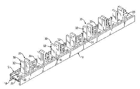
9 With reference to Figs. 1 to 3, a first embodiment of a hand tool frame
in
accordance with the present invention comprises a track base 10, a positioning
11 board 20, and at least one pair of positioning mounts 30.
12 The track base 10 may be made of aluminum, is an elongated seat and
13 has a bottom panel 11, a slide rail 12, a connecting track 13, and a
closed track 14.
14 The bottom panel 11 is elongated and has a top surface, a bottom
surface, a front
end, and a rear end. The slide rail 12 is formed on and protrudes upwardly
from
16 the top surface of the bottom panel 11 between the front end and the
rear end of
17 the bottom panel 11 and has a top side, a top opening 121, and a sliding
recess
18 122. The top opening 121 is formed through the top side of the slide
rail 12. The
19 sliding recess 122 is formed in the slide rail 12 between the top side
of the slide
rail 12 and the top surface of the bottom panel 11 and communicates with the
top
21 opening 121.
22 The connecting track 13 is formed on and protrudes downwardly from
23 the bottom surface of the bottom panel 11, and has a top side, a
communicating
24 opening 131, and a connecting recess 132. The top side of the connecting
track
CA 02925322 2016-03-29
1 13 is formed on and protrudes from the bottom surface of the bottom panel
11.
2 The communicating opening 131 is formed through the top side of the
3 connecting track 13 and the bottom surface of the bottom panel 11, and
4 communicates with the sliding recess 122 of the slide rail 12. The
connecting
5 recess 132 is formed between the bottom panel 11 and the connecting track
13
6 and communicates with the communicating opening 131. Additionally, a
width
7 of the communicating opening 131 of the connecting track 13 is narrower
than a
8 width of the top opening 121 of the slide rail 12.
9 The closed track 14 is formed on and protrudes downwardly from the
bottom surface of the bottom panel 11 around the connecting track 13 and has a
11 bottom side and a bottom opening 141 formed through the bottom side of
the
12 closed track 14. In addition, the closed track 14 and the slide rail 12
are formed
13 on the bottom panel 11 as a single piece.
14 The positioning board 20 is elastic, is mounted in the connecting track
13 of the track base 10 and has two long opposite sides, a front end, a rear
end, a
16 middle, a top surface, a bottom surface, two rail bars 21, a through
recess 22, and
17 multiple engaging holes 23. The positioning board 20 is bent upwardly
from the
18 long opposite sides of the positioning board 20 to the middle of the
positioning
19 board 20. Then, the top surface of the positioning board 20 at the
middle of the
positioning board 20 extends at the communicating opening 131 of the
21 connecting track 13.
22 The rail bars 21 are formed on and protrude downwardly from the
23 bottom surface of the positioning board 20 respectively at the two long
opposite
24 sides of the positioning board 20 and are mounted in the connecting
recess 132 of
CA 02925322 2016-03-29
6
1 the connecting track 13.
2 The through recess 22 is formed in the bottom surface of the positioning
3 board 20 at the middle of the positioning board 20 between the front end
and the
4 rear end of the positioning board 20, is parallel with the long opposite
sides of
the positioning board 20 and communicates with the connecting recess 132 of
6 the connecting track 13. Then, a space is formed between the connecting
track 13
7 and the middle of the positioning board 20, and the space may allow the
middle
8 of the positioning board 20 to deform relative to the track base 10.
9 The engaging holes 23 are formed through the top surface and the
bottom surface of the positioning board 20 at the middle of the positioning
board
11 20, communicate with the connecting recess 132 of the connecting track
13 via
12 the through recess 22 and communicate with the sliding recess 122 of the
slide
13 rail 12 via the communicating opening 131 of the connecting track 13.
14 The at least one pair of positioning mounts 30 are slidably mounted on
the track base 10, and each one of the at least one pair of positioning mounts
30
16 has a sliding seat 31, an extending element 32, and a pressing arm 33.
17 The sliding seat 31 is slidably mounted in the sliding recess 122 of the
18 slide rail 12 and abuts the positioning board 20. The sliding seat 31
has a body
19 311, a positioning portion 312, two through slots 313, and an engaging
protrusion 314. The body 311 is U-shaped, is slidably mounted in the sliding
21 recess 122 of the slide rail 12 and has a bottom side, a top side, two
free ends, and
22 a middle. The bottom side of the body 311 faces the communicating
opening 131
23 of the connecting track 13 and abuts the top surface of the positioning
board 20.
24 The top side of the body 311 faces the top opening 121 of the slide rail
12. The
CA 02925322 2016-03-29
1 middle of the body 311 is formed between the two free ends of the body
311.
2 The positioning portion 312 is elastic, is formed on and protrudes
3 transversally from the middle of the body 311, and has a bottom surface
and a top
4 surface. The bottom surface of the positioning portion 312 abuts the top
surface
of the positioning board 20. The through slots 313 are respectively formed
6 through the body 311 between the free ends of the body 311 and the
positioning
7 portion 312, and this makes the positioning portion 312 elastomeric
relative to
8 the body 311. Then, the positioning portion 312 of the sliding seat 31
may be
9 deformed to separate from the top surface of the positioning board 20.
The engaging protrusion 314 is formed on and protrudes downwardly
11 from the bottom surface of the positioning portion 312, and selectively
engages
12 with one of the engaging holes 23 of the positioning board 20. Then, the
sliding
13 seat 31 may be securely mounted on the positioning board 20 without
sliding
14 relative to the track base 10 by the engagement between the engaging
protrusion
314 and a corresponding engaging hole 23 of the positioning board 20.
16 The extending element 32 is formed on and protrudes upwardly from the
17 sliding seat 31 and extends out of the slide rail 12 via the top opening
121. The
18 extending element 32 is used to clamp a hand tool. Furthermore, in the
first
19 embodiment of the hand tool frame, the extending element 32 of each one
of the
at least one pair of positioning mounts 30 is a clamping arm and is formed on
the
21 top side of the body 311 of the sliding seat 31 and has a free end, an
inner side, an
22 outer side, and a holding hook 321. The free end of the extending
element 32
23 extends out of the slide rail 12 via the top opening 121. The inner
sides of the
24 extending elements 32 of the at least one pair of positioning mounts 30
face to
CA 02925322 2016-03-29
8
1 each other. The outer side of the extending element 32 is opposite to the
inner
2 side of the extending element 32. The holding hook 321 is formed on and
3 protrudes from the inner side of the extending element 32 at the free end
of the
4 extending element 32. The holding hooks 321 of the at least one pair of
positioning mounts 30 face to each other, and a holding space is formed
between
6 the extending elements 32 of the at least one pair of positioning mounts
30.
7 The pressing arm 33 is formed on and protrudes upwardly from the
8 bottom side of the body 311 of the sliding seat 31 and has an upper end
extending
9 out of the slide rail 12 via the top opening 121.
With reference to Fig. 3, when the hand tool frame of the first
11 embodiment in the present invention is in use, the holding space between
the
12 extending elements 32 of the at least one pair of positioning mounts 30
may be
13 adjusted by pressing the pressing arms 33 respectively toward the
extending
14 elements 32 of the at least one pair of positioning mounts 30 to enable
the two
engaging protrusions 314 of the sliding seats 31 to respectively disengage
from
16 two corresponding engaging holes 23 of the positioning board 20. Then,
the
17 sliding seats 31 of the at least one pair of positioning mounts 30 may
be pushed
18 to slide along the positioning board 20 relative to the track base 10.
After the
19 holding space between the at least one pair of positioning mounts 30 is
adjusted,
the at least one pair of positioning mounts 30 may be positioned on the
21 positioning board 20 by the engagement between the engaging protrusions
314
22 and two corresponding engaging holes 23.
23 With reference to Fig. 4, different kinds of hand tools such as pliers
70,
24 combination spanners 71, adjustable wrenches 72, socket wrenches 73,
CA 02925322 2016-03-29
9
1 hexagonal wrenches 74 or screwdrivers 75 may be inserted into the holding
2 space that is formed between the extending elements 32 of the at least
one pair of
3 positioning mounts 30, and the holding hooks 321 securely clamp the hand
tools
4 to prevent the hand tools separating from the at least one pair of
positioning
mounts 30. When the hand tool frame of the first embodiment in the present
6 invention is moved or someone hits the hand tools that are stored on the
track
7 base 10, the hand tools are still securely clamped between the positioning
8 mounts 30 without changing positions or separating from the positioning
mounts
9 30. Then, the user doesn't need to adjust the positions of the hand tools
after
moving the hand tool frame, and the hand tools are securely clamped between
11 the positioning mounts 30 and will not injure the users.
12 With reference to Figs. 5 and 6, a second embodiment of a hand tool
13 frame in accordance with the present invention is substantially the same
as the
14 first embodiment except for the following features. The hand tool frame
further
has an extending track base 10A and an additional positioning board 20A. The
16 extending track base 10A is connected to and parallel with the track
base 10 by
17 an extending panel 15A. The additional positioning board 20A is mounted
in the
18 extending track base 10A, and the structure of the additional
positioning board
19 20A is substantially the same as the positioning board 20.
Furthermore, in the second embodiment, the hand tool frame has at least
21 one positioning mount 30A, and the at least one positioning mount 30A is
22 mounted in the track base 10 or the extending track base 10A, and each
one of
23 the at least one positioning mount 30A has a sliding seat 31A, an
extending
24 element 32A, and a pressing arm 33A. The sliding seat 31A is slidably
mounted
CA 02925322 2016-03-29
1 in the track
base 10 or the extending track base 10A. The extending element 32A
2 is a hollow
block, is formed on the top side of the sliding seat 31A, and has two
3 sidewalls, a top
side, at least one tool hole 322A, a tool slot 323A, and a
4 mounting slit
324A. The at least one tool hole 323A is formed through the
5 sidewalls of the
extending element 32A to hold a shank 751 of a screwdriver 75
6 as shown in Fig.
8. The tool slot 323A is formed through the sidewalls of the
7 extending
element 32A and communicates with the at least one tool hole 322A.
8 The mounting
slit 324A is formed through the top side and the sidewalls of the
9 extending
element 32A and communicates with the at least one tool hole 322A
10 opposite to the tool slot 323A. =
11 With reference
to Fig. 7, when the hand tool frame of the second
12 embodiment in
the present invention is in use, two positioning mounts 30A that
13 are respectively
mounted in the track bases 10, 10A are respectively moved
14 along the
positioning board 20, 20A relative to the track base 10, 10A by
pressing the pressing arms 33A to enable the engaging protrusions 314A to
16 respectively
disengage from two engaging holes 23, 23A of the positioning
17 boards 20, 20A.
When the two positioning mounts 30A respectively in the track
18 bases 10, 10A
align with each other, the user may release the pressing arms 33A
19 of the two
positioning mounts 30A to enable the engaging protrusions 314A to
respectively engage two engaging holes 23, 23A of the positioning boards 20,
21 20A.
22 With reference
to Fig. 8, a shank 751 of a screwdriver 75 is inserted into
23 two positioning
mounts 30A that are respectively mounted in the track bases 10,
24 10A via the
mounting slits 324A of the extending elements 32A, and is held
CA 02925322 2016-03-29
11
1 between two tool holes 323A of the extending elements 32A. Since the
2 positioning mounts 30A are securely mounted on the track bases 10, 10A by
the
3 engagement between the positioning mounts 30A and the positioning boards
20,
4 20A, the screwdrivers 75 may be securely held on the track bases 10, 10A
of the
hand tool frame. Then, when the hand tool frame of the second embodiment in
6 the present invention is moved or someone hits the hand tools that are
stored on
7 the track bases 10, 10A, the hand tools are still securely clamped
between the
8 positioning mounts 30A without changing positions or separating from the
9 positioning mounts 30A. Then, the user doesn't need to adjust the
positions of
the hand tools after moving the hand tool frame, and the hand tools are
securely
11 clamped between the positioning mounts 30A and will not injure the
users.
12 With reference to Figs. 9 and 10, a third embodiment of a hand tool
13 frame in accordance with the present invention is substantially the same
as the
14 first embodiment except for the following features. The hand tool frame
further
has an outer frame 40 connected to the track base 10 and having a first
16 supporting mount 41, two side supporting racks 42, two clamping panels
43, and
17 a second supporting mount 44.
18 The first supporting mount 41 is connected to the front end of the track
19 base 10 to provide a holding effect to a user and has a length. The side
supporting
racks 42 are connected to the first supporting mount 41 beside the track base
10.
21 The clamping panels 43 are respectively mounted in the side supporting
racks 42,
22 and each one of the clamping panels 43 has multiple clamping claws 431
23 continuously formed on a top side of the clamping panel 43 and extending
out of
24 a corresponding side supporting rack 42. The second supporting mount 44
is
CA 02925322 2016-03-29
12
1 connected to the rear end of the track base 10, is connected to the side
supporting
2 racks 42, and has a length longer than the length of the first supporting
mount 41.
3 Then, the outer frame 40 is formed as a trapezoid frame by the supporting
4 mounts 41, 44 and the side supporting racks 42.
The at least one positioning mount 30B is mounted in the track base 10,
6 and each one of the at least one positioning mount 30B has a sliding seat
31B, an
7 extending element 32B, and a pressing arm 33B. The sliding seat 31B is
slidably
8 mounted in the slide rail 12 of the track base 10. The extending element
32B is an
9 elastic arm, is formed on the sliding seat 31B, and has a curved segment
325B
and a limiting segment 326B. The curved segment 325B is curvedly formed on
11 and protrudes from the sliding seat 31B and has a free end extending out
of the
12 slide rail 12. The limiting segment 326B is formed on and protrudes from
the
13 free end of the curved segment 325B of the extending element 32B to abut
14 against a combination spanner 71 as shown in Figs. 11 and 12.
With reference to Figs. 11 and 12, when combination spanners 71 of
16 different sizes are mounted on the third embodiment of the hand tool
frame, the
17 combination spanners 71 are held in the clamping claws 431 of the
clamping
18 panels 43, and the position of the extending element 32B of each one of
the
19 positioning elements 30B may be adjusted by pressing the pressing arm
33B to
release the engagement that is formed between the engaging protrusion 314B
21 and a corresponding engaging hole 23 of the positioning board 20 and
moving
22 the positioning mounts 30B relative to the track base 10 to enable the
limiting
23 segment 326B of the extending element 32B to move close to and abut
against a
24 corresponding combination spanner 71. Furthermore, the curved segment
325B
CA 02925322 2016-03-29
13
1 of the extending element 32B may be elastically deformed to closely abut
against
2 the corresponding combination spanner 71. Then, the combination spanners
71
3 of different sizes can be securely held on the hand tool frame between
the
4 clamping claws 431 of the clamping panels 43 and the positioning elements
30B.
Therefore, when the hand tool frame of the third embodiment in the present
6 invention is moved or someone hits the hand tools that are stored on the
track
7 base 10, the hand tools are still securely clamped between the positioning
8 mounts 30B and the outer frame 40 without changing positions or
separating
9 from the positioning mounts 30B and the outer frame 40. Then, the user
doesn't
need to adjust the positions of the hand tools after moving the hand tool
frame,
11 and the hand tools are securely clamped between the positioning mounts
30B
12 and the outer frame 40 and will not injure the users.
13