Note: Descriptions are shown in the official language in which they were submitted.
CA 02925397 2016-03-24
WO 2015/047083 1
PCT/NL2014/000034
TITLE OF THE INVENTION
SUBSTANCE INTRODUCTION METHOD FOR PLANT AND PLANT OBTAINED
THEREWITH
BACKGROUND OF THE INVENTION
The invention relates to a substance introduction method for a plant, in
particular a pot
plant, e.g. an orchid.
Over the years many different substance introduction methods have been
developed to
introduce all kinds of substances into a plant, mainly by fluid introduction,
which
substances may comprise pesticides, fungicides, nutrients, water, flavorants,
odorants,
colorants and suitable solutions thereof.
An example of a prior art substance introduction method can be found in
international
patent publication W093/02546 in which hollow spikes, which are in
communication with a
reservoir, are pressed into the stem of a plant, such that a transverse
passageway of the
spikes is located within the xylem system of the plant. Any fluid inside the
reservoir is then
taken up by the plant using the transpiration pull of the xylem system.
A disadvantage of W093/02546 is that the system required to perform this
method is
rather complex. Fabricating and subsequent positioning the spikes with the
transverse
passageways is not easy.
Another example of a prior art substance introduction method can be found in
international patent publication W087/01559 in which an unpressurized
reservoir is
connected to the plant via a probe that is able to penetrate the epidermis of
the stem of
the plant.
A disadvantage of W087/01559 is that the construction with the reservoir and
probes is
relatively large compared to the size of the stem of the plant, so that
additional mounting
aids are required. An additional disadvantage of using probes or needles, e.g.
hypodermic
needles, that remain connected to the stem during the substance introduction
is that there
is a significant risk to damage the stem of the plant while handling the
probe/needle due to
the sharp tip of the probe/needle.
CA 02925397 2016-03-24
WO 2015/047083 2
PCT/NL2014/000034
Another example of a prior art substance introduction method can be found in
international patent publication W02012/067496 in which the roots of the plant
are
physically injured and subsequently the injured roots are brought into contact
with a fluid.
A disadvantage of W02012/067496 is that the plant is severely injured with the
chance of
the plant dying and that the method is laborious, because of the many steps
required, as
for instance the plant needs to be taken out of the soil to injure the roots.
A further example of a prior art substance introduction method can be found in
European
patent publication EP2.308.282 in which a hole is made into the stem of the
plant to
receive the tip of a pipette, which pipette needs to be fixed to the plant
until the fluid is
absorbed by the plant.
A disadvantage of EP2.308.282 is that it is not easy to fix the pipette to the
plant without
leakage.
Yet another example of a prior art substance introduction method can be found
in French
patent publication FR2.879.073 in which the plant is watered with a substance
containing
fluid, which is then absorbed by the roots in a natural way.
A disadvantage of FR2.879.073 is that in order for the plant to absorb a
certain amount of
fluid, a multiple of that amount needs to be introduced into the soil around
the plant.
Hence, the efficiency is very low compared to methods where the substance
containing
fluid is administered to the plant in a more direct way.
Another example of a prior art substance introduction method can be found in
international patent publication W02010/085082 in which branches are cut and a
storage
tube is coupled to the cut branch to introduce fluid into the plant.
A disadvantage of W02010/085082 is that cutting the branches is not possible
or desired
for all types of plants, that it is not the most efficient method, that it
reduces the value of
the plant, and that it requires special measures to make a proper seal between
the tube
and the cut branch in order to prevent fluid from unintentionally leaking away
between the
tube and the branch.
A further example of a prior art substance introduction method can be found in
US patent
publication US6.405.480 in which a reservoir is formed around the cut stem of
a
CA 02925397 2016-03-24
WO 2015/047083 3
PCT/NL2014/000034
Christmas tree, so that fluid can be forced into the stem to prevent the tree
from drying
and becoming a fire hazard.
US6.405.480 assumes that the stem is cut, which is usually the case with a
Christmas
tree, but is most of the time for all other purposes not desired. Further, the
disclosure is
complex to implement in practice for a pot plant when the intention is to keep
the plant
alive for more than a couple of weeks.
Substances may be introduced into plants for different reasons. Pesticides,
nutrients, etc.
are usually introduced to improve the well-being of the plant, while
flavorants, colorants,
odorants and the like are introduced to improve the esthetic value perceived
by customers
buying or using the plants. It is known that some of these substances may be
harmful to
the plant and that depending on, amongst others, the substance introduction
method the
life of the plants is shortened or some parts of the plant, such as the
flowers or buds, die
easily and/or quickly.
BRIEF SUMMARY OF THE INVENTION
In view of the above it is an object of the invention to provide an improved
method for
introducing a substance into a plant, in particular a pot plant.
To achieve this object, there is provided a method for introducing a substance
into a plant,
in particular a pot plant, wherein said method comprises the following steps:
- forming a final hole into a stem of the plant, wherein the final
hole is accessible via
an opening in an outer surface of the stem, and wherein the final hole has a
dimension in a direction parallel to a longitudinal axis of the stem which is
larger
than a maximum dimension of the opening in said direction parallel to the
longitudinal axis of the stem;
- subjecting the interior of the final hole to the substance by
introducing the
substance through the opening.
A main advantage of the invention is that the hole is enlarged in the
direction parallel to
the longitudinal axis of the stem such that the area of the interior wall is
increased
compared to prior art methods, resulting in more tissue of the plant being
subjected to the
substance. The effect is that the substance is easier and more quickly
absorbed by the
plant.
CA 02925397 2016-03-24
WO 2015/047083 4
PCT/NL2014/000034
An example in which the enlarged hole is advantageous is in case an air bubble
gets
trapped within the final hole. This air bubble may at least partially block
the taking up of
substance by the plant. By enlarging the hole, the negative effect of a
trapped air bubble
is diminished.
The fact that the size of the opening providing access to the final hole seen
in a direction
parallel to the longitudinal axis of the stem of the plant is smaller than a
corresponding
size of the final hole in said direction also allows to more easily close the
opening after
substance introduction and/or keeps the introduced weakening of the stem of
the plant
within limits.
In an embodiment, forming the final hole comprises the steps of forming an
initial hole with
corresponding opening in the stem of the plant, and subsequently extending the
size of
the initial hole through the already made opening in the stem of the plant.
This provides a
two-step process which in general is easier to perform than a one-step
process. However,
an advantage of the one-step process is that it can be performed faster.
A hole in this specification is broadly defined and includes any cavity, cut
or passageway
extending from an opening in an outer surface of the stem into the interior of
the stem
allowing the interior of the stem to be exposed to a substance entering the
plant via the
opening. As an example, making a longitudinal cut in the stem of the, plant
falls within this
definition when this results in an opening in the outer surface of the stem
through which a
substance can enter the interior of the stem of the plant. Hence, in case a
cut is made with
a very thin blade resulting in injuring the stem of the plant, but in which
the opposing walls
of the cut are sealed together after removal of the very thin blade, so that
no substance
can enter the interior of the stem of the plant, this is not a hole as defined
in this
specification.
In an embodiment, forming the final hole comprises one or more of the
following
operations: drilling, cutting, suction, vaporizing, lasering, chemical etching
and piercing. In
an embodiment, the initial hole may be formed by drilling, cutting, suction,
vaporizing,
lasering, chemical etching and/or piercing. Extending the size of the initial
hole may also
comprise drilling, cutting, suction, vaporizing, lasering, chemical etching
and/or piercing,
wherein preferably forming the final hole and extending its size may be done
using
identical operations or using different operations.
CA 02925397 2016-03-24
WO 2015/047083 5
PCT/NL2014/000034
In an embodiment, the initial hole is formed by inserting a first tool into
the stem in a
direction perpendicular to a longitudinal axis of the stem, wherein the size
of the initial
hole is extended, i.e. increased, by again introducing the first tool or by
introducing a
second tool through the opening in the stem in a direction making an acute
angle with the
longitudinal axis of the stem. An advantage of this embodiment is that the
initial hole is
easily made due to the perpendicular direction, and the more complex extension
of the
initial hole is done using the opening in the stem as a guidance, thereby
making this
method step easier to perform.
In an embodiment, the initial hole is formed by drilling into the stem of the
plant, wherein if
desired a stop may be used during drilling to prevent the drill bit from
drilling through the
stem of the plant.
In an embodiment, the method according to the invention comprises the steps:
- forming an initial hole into the stem of the plant, wherein the initial hole
has a
substantially constant cross-section corresponding to an opening of the
initial hole
at an outer surface of the stem of the plant, and wherein the initial hole
extends
from the opening of the initial hole perpendicular to a longitudinal axis of
the stem
of the plant;
- extending the size of the initial hole in a direction parallel to the
longitudinal axis of
the stem of the plant via the opening of the initial hole, thereby forming a
final hole
according to the invention, wherein extending involves removing plant material
via
the opening of the initial hole.
Removing plant material has the advantage that the volume of the final hole is
increased
allowing to store more substance into the stem.
In an embodiment, the size of the initial hole is extended at least in a
direction away from
the roots of the plant, which is the direction in which the introduced
substances need to
travel in most cases.
In an embodiment, the size of the initial hole is also extended in a direction
towards the
roots of the plant as this also increases the hole and the area of the
interior wall that is
subjected to the substance and thus aids in the substance absorption process
of the plant.
In an embodiment, forming the initial hole comprises inserting a hypodermic
needle with a
beveled tip into the stem and subsequently rotating the needle about its
longitudinal axis,
wherein during these steps the longitudinal axis of the needle is
perpendicular to a
CA 02925397 2016-03-24
WO 2015/047083 6
PCT/NL2014/000034
longitudinal axis of the stem. In this way, the side edges of the beveled tip
can cut through
the plant tissue when rotating the needle. An advantage of using a hypodermic
needle in
this way is that a standard tool can be used instead of a custom made tool,
and that a
hypodermic needle is hollow allowing to receive plant material during the
cutting action.
In an embodiment, extending the size of the initial hole and/or removing plant
material
comprises inserting a hypodermic needle with a beveled tip through the opening
of the
initial hole into the stem and subsequently rotating the needle about its
longitudinal axis,
wherein during these steps the longitudinal axis of the needle makes an acute
angle with
respect to a longitudinal axis of the stem, preferably an angle between 30-60
degrees,
more preferably 45 degrees. By rotating the needle, the side edges of the
beveled tip can
cut through the plant tissue.
In a preferred embodiment, the tip of the hypodermic needle is directed
towards a free
end of the stem of the plant, i.e. away from the roots, which is most of the
times upwards,
so that an additional cavity is formed above the opening in the stem of the
plant.
Additionally or alternatively a cavity may be formed below the opening in the
stem of the
plant.
In an embodiment, extending the size of the initial hole and/or removing plant
material
comprises introducing an instrument or tool provided with cutters into the
initial hole via
the opening, extending said cutters in a direction parallel to the
longitudinal direction of the
stem of the plant, retracting the cutters, and withdrawing the instrument or
tool from the
hole. In this way, the instrument and/or tool can be easily introduced into
the already
formed initial hole and the size can be extended by subsequently operating the
cutters.
In an embodiment, forming the final hole comprises removing plant tissue from
the stem of
the plant, preferably during the formation of an initial hole and additionally
or alternatively
during extending the size of the initial hole. Removing plant tissue has the
advantage that
the internal volume of the final hole is increased allowing to receive more
substance into
the final hole.
In an embodiment, removing plant material comprises suction and/or cutting. In
an
embodiment, specific organisms, e.g. animals, insects, bacteria, etc., may be
used to eat
away the plant material in order to form the initial and/or the final hole.
CA 02925397 2016-03-24
7
WO 2015/047083
PCT/NL2014/000034
In an embodiment, no plant material is removed while forming the final hole,
so that the
final hole mainly comprises of cuts in the stem of the plant, which expose the
internal
tissue of the plant to the substance.
In an embodiment, the size of the opening in the stem of the plant is
specifically chosen to
set a desired flow rate or flow resistance, wherein the hole inside the stem
of the plant is
made large enough by applying the invention to ensure that the opening forms
the main or
dominant flow resistance. Substance introduced via the opening in the stem of
the plant
may mix with fluids coming from the roots of the plant. By setting the flow
rate or flow
resistance through the opening in the stem, the mix ratio may be set. The mix
ratio may
for instance be used to obtain a desired effect, e.g. the mix ratio may
determine the
appearance of flowers when a colorant is introduced via the opening in the
stem of the
plant. Further, the mix ratio may also be set to keep the plant healthy in
case the
introduced substance may negatively affect the health of the plant, especially
in case the
introduced substance negatively affect the health of the plant only at
relatively high doses.
It is explicitly mentioned here that the invention is not limited to final
holes with only a
single opening allowing access to the interior of the final hole. The
invention may also be
applied to a final hole comprising multiple openings, as is for instance the
case when the
initial hole is a through-hole, which through-hole may e.g. be made by
drilling through the
stem of the plant. However, the feature that the final hole has a dimension in
a direction
parallel to a longitudinal axis of the stem of the plant larger than the a
maximum
dimension of the opening in said direction has to be satisfied by all openings
providing
access to the final hole in order to be in accordance with the invention.
It will be clear to the skilled person that the substances to be introduced
into the plant may
be introduced in any form including solid substances, e.g. powder, fluidic
substances,
such as liquids, gasses, solutions, etc. or semi-solid substances such as
pastes. In an
embodiment it is possible to mix substances inside the final hole. For
instance, a colorant
may be introduced in the final hole in powder form and subsequently a liquid,
e.g. water,
may be introduced into the final hole to dissolve the powder into the water to
get a solution
that can be taken up by the plant.
The substances introduced or to be introduced into the plant may include:
- pesticides;
- fungicides;
- nutrients;
CA 02925397 2016-03-24
WO 2015/047083 8
PCT/NL2014/000034
- flavorants;
- colorants;
- odorants;
and any mixtures or suitable solutions thereof.
The substance may alternatively be referred to as matter, component,
ingredient, element,
constituent, material or essence, and for instance also as compound, mixture,
blend or
composition when the substance contains multiple ingredients.
The final hole in the stem of the plant may be a through hole, such that two
openings are
formed in the stem of the plant, but in a preferred embodiment, the final hole
is a blind
hole, wherein preferably the depth of the final hole is larger than the radius
of the stem of
the plant.
The diameter of the opening of the final hole is preferably above the 2mm,
more
preferably 3mm. The maximum diameter is determined by the diameter of the stem
of the
plant.
When the introduction of substance into the plant is or has ended, the final
hole may have
to be closed in order to prevent the plant from dying. The final hole may be
closed after
removal of components used to introduce substances into the plant via the
final hole, such
as pipettes, needles, etc.
The step of closing the final hole may comprise providing the interior wall of
the final hole
with a layer of material preventing said wall from drying, i.e. applying a
layer of material to
the interior wall. This layer of material may for instance be sprayed into the
final hole or by
exposing the interior of the final hole to a solution such that a layer of
material is deposited
on the interior wall of the final hole.
The final hole in the stem is preferably closed using wax, preferably bee wax,
and/or the
interior wall is provided with a layer of wax, preferably also bee wax.
Providing a layer of
material on the interior wall of the final hole and closing the final hole may
be done in a
single operation by completely filling the final hole with material, e.g. the
bee wax.
The invention also relates to a plant, in particular a pot plant, provided
with a final hole into
its stem, wherein the final hole is accessible via an opening in an outer
surface of the
stem, and wherein the final hole has a dimension in a direction parallel to a
longitudinal
CA 02925397 2016-03-24
9
WO 2015/047083
PCT/NL2014/000034
axis of the stem which is larger than a maximum dimension of the opening in
the direction
parallel to the longitudinal axis of the stem
In an embodiment, when seen in longitudinal direction of the stem of the
plant, the final
hole extends at least in a direction away from the roots of the plant.
In an embodiment, the final hole also extends in a direction towards the roots
of the plant.
In an embodiment, the interior wall of the final hole is covered with a layer
of material
preventing the interior wall from drying.
In an embodiment, the final hole is closed off by material preventing the
interior of the final
hole from drying. This material may be wax, preferably bee wax.
Preferably the plant is not a woody stemmed type plant, but comprises soft
stem tissue
with hard outer wall (e.g. cuticle) or epidermis (e.g. as in herbaceous
plants). The plant is
preferably a plant that at least in its youth stage has stems that are not
lignified. The plant
is preferably a herbaceous plant with soft stem tissue.
Preferably the plant is a vascular plant, more preferably a plant in the
orchid family
(orchidaceae) and most preferably the plant is a Phalaenopsis orchid or a
Denbromium
orchid.
The hole in the stem preferably has a depth which is larger than a radius of
the stem at
the location of the hole. The depth of the hole may for instance be between
50% and 90%
of the diameter of the stem, preferably between 60% and 90% of the diameter of
the stem,
and more preferably between 75% and 85% of the diameter of the stem. The
diameter of
the hole may be in the range of 30% to 70% of the diameter of the stem and is
preferably
between 40% to 60% of the diameter of the stem. The depth of the final hole is
preferably
such that the xylem system on both sides of the stem can be used to transport
substances
introduced into the final hole.
In an embodiment, the final hole is filled with wax to close off the opening
in the outer
surface of the stem.
CA 02925397 2016-03-24
WO 2015/047083 10
PCT/NL2014/000034
BRIEF DESCRIPTION OF THE DRAWINGS
The invention will now be described in a non-limiting way with reference to
the
accompanying drawings in which like parts are indicated by like reference
symbols and in
which:
Fig. 1 depicts schematically a plant, in particular a pot plant;
Fig. 2 depicts a cross-section of a stem of a plant in which an
initial hole is formed
in accordance with an embodiment according to the invention;
Fig. 3 depicts a cross-section of a stem of a plant in which a final
hole is formed in
accordance with an embodiment according to the invention; and
Fig. 4A-4C depict the formation of a final hole according to another
embodiment of the
invention.
DETAILED DESCRIPTION OF THE INVENTION
Fig. 1 depicts a schematic drawing of a plant P, in particular a pot plant.
Fig. 1 shows
schematically the different parts of a plant. The shown parts of a plant are
the root system
RS, the stem structure including the stems MS, FS, FS1, FS2, FS3, FS3A, FS3B
of the
plant, the leaves L of the plant, the flowers FL of the plant and the buds B
of the plant P.
The root system RS of the plant is the non-leaf, non-nodes bearing part of the
plant P.
The major functions of the root system RS may be one or more of the following:
1) absorption of water and inorganic nutrients;
2) anchoring of the plant body to the ground or any other base structure and
supporting it;
3) storage of food and nutrients;
4) vegetative reproduction.
The root system RS forms one end of the plant P, the flowers FL, leaves L and
buds B
form the other end of the plant P. In the schematic drawing of Fig. 1 a non-
fruit bearing
plant is shown, but it will be apparent that a plant P may also comprise
fruits as it
comprises leaves L, flowers FL and buds B.
The stem structure connects the flowers FL, leaves L and buds B to the root
system RS
and has one or more of the following functions:
1) support for and the elevation of leaves L, flowers FL and/or fruits;
2) transport of fluids between roots and the leaves L, flowers FL and/or
fruits;
3) storage of nutrients; and
4) production of new living tissue.
CA 02925397 2016-03-24
WO 2015/047083 11 PCT/NL2014/000034
In the shown example, the plant P comprises a main stem MS which acts as the
main
support for all other plant parts except the root system RS and through which
all fluids
passes. In this example, the main stem MS supports the leaves L and other
stems, in this
case flower stem FS. The flower stem FS in turn is split up into three flower
sub-stems
FS1, FS2, FS3. Flower sub-stems FS1 and FS2 each carry one flower FL. Flower
sub-
stem FS3 is split into sub-stems FS3A and FS3B each carrying a bud B, which
will later
on develop into a flower FL as well. It will be apparent to the skilled person
that the shown
structure of the stems is a mere example and that the plant may also have a
different
configuration.
The method described in this specification may be applied to all kind of stems
of the stem
structure. However, in practice, the user will choose a specific stem for
carrying out the
method depending on the purpose, i.e. the intended destination, of the
substances to be
introduced into the plant.
When for instance the substance is intended for only the leaves L of the plant
P of Fig. 1
or for all leaves L, flowers FL and buds B, the method will preferably be
carried out in
relation to the main stem MS, as introducing the substance into the main stem
MS will
result in the substance being distributed to all parts of the plant P carried
by the main stem
MS.
When for instance the substance is not intended for the leaves L but for the
flowers FL
and buds B, the method is preferably carried out in relation to the flower
stem FS.
Likewise, if the substance is only intended for the buds B and not for any
other part of the
plant, the method is preferably carried out in relation to the flower sub-stem
FS3. As the
methods can be applied to all kind of stems, only the general term stem is and
will be
used throughout the remaining detailed description of the invention.
It will be apparent to the skilled person that alternative to choosing a
single specific stem,
it is also possible to carry out the method in relation to multiple stems of a
plant P,
possibly simultaneously. For instance, if a substance is intended for the
flowers FL and
buds B, the method may be carried out in relation to flower stem FS as
described above,
but alternatively, the method may also be carried out in relation to flower
sub-stems FS1,
FS2 and FS3.
CA 02925397 2016-03-24
WO 2015/047083 12
PCT/NL2014/000034
Figure 2 depicts a cross-section of a stem S of a plant, e.g. a plant
according to Fig. 1.
The stem S of a plant is usually divided into nodes N and internodes IN in
between nodes
N. The nodes N may hold buds (not shown here) which grow into one or more
leaves,
sub-stems or flowers as shown in Fig. 1.
The stem comprises dermal tissue DT, which may alternatively be referred to as
epidermis, defining an outer surface OS of the stem S and usually functions to
waterproof,
protect and control gas exchange. Plant tissue TI below the dermal tissue
comprises
vascular tissue and ground tissue filling in around the vascular tissue. The
vascular tissue
provides long distance transport in the form of xylem and phloem,
alternatively referred to
as xylem system and phloem system of a plant. The substance introduction
methods
described in this specification rely amongst others on the xylem and/or phloem
transport
systems in order to distribute the introduced substance throughout the plant,
where the
xylem is preferred as it has a single known transport direction where the
phloem may be
multi-directional. Hence, the distribution of the substance throughout the
plant via the
xylem system is more predictable.
The stem S defines a longitudinal axis LA. This allows to define and describe
some
directions in relation to the longitudinal axis. A first direction DL is
oriented parallel to the
longitudinal axis LA of the stem, a second direction PD is oriented
perpendicular to the
longitudinal axis LA of the stem, and a third direction is a circumferential
direction CD
around the longitudinal axis LA of the stem.
Fig. 2 depicts an initial hole IH. Below it will be assumed that the situation
in Fig. 2 is an
intermediate situation between forming the initial hole and the formation of
the final hole.
The initial hole IH in Fig. 2 extends from an opening OP in the outer surface
OS of the
stem S in the second direction PD into the tissue TI, so beyond the dermal
tissue DT in
order to get access to the long distance transportation system, preferably the
xylem. The
depth D1 of the initial hole in this example is larger than the radius of the
stem at this
location, and is in this case also larger than the diameter D2 of the hole IH.
The initial hole IH comprises a interior wall IW delimiting the initial hole
from the tissue in
the stem of the plant. When a substance is introduced into the initial hole,
the substance
needs to penetrate the plant by passing the interior wall IW in order to be
taken up by the
plant, e.g. by the transportation system of the plant.
CA 02925397 2016-03-24
WO 2015/047083 13
PCT/NL2014/000034
The initial hole IH may be formed by drilling or cutting, but in an embodiment
is formed by
inserting a hypodermic needle with a beveled tip into the stem. The beveled
tip has the
advantage that the needle has a sharp tip able to penetrate the dermal tissue
and that the
entire beveled portion of the tip forms a cutting surface which can be used to
form the
initial hole by subsequent rotation of the needle about its longitudinal axis,
preferably after
it has been brought to the desired depth Dl. Rotating the needle will then cut
through the
tissue and allow for easy removal of the plant tissue.
Although the shown hole IH is a clean hole from which all plant material has
been
removed, it is also possible that the hypodermic needle only makes a circular
cut without
removing the tissue inside.
When the hypodermic needle is manually inserted into the stem of the plant, it
can be
advantageous to use a hypodermic needle of which the length of the beveled tip
is
substantially the same as the desired hole depth Dl. In that case, the
hypodermic needle
can be inserted into the stem until the first moment the beveled tip is
completely inserted
into the stem. This will aid in preventing the hypodermic needle from being
inserted too
deep and extending through the plant on the opposite side of the opening OP.
In that way,
it is ensured that a blind hole as in Fig. 2 is formed. However, it is also
possible, but not
preferred to make a through hole. In that case, no precautions preventing a
tool from
extending through the stem need to be taken.
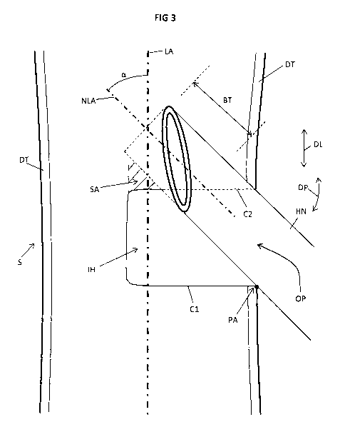
Fig. 3 depicts the formation of a final hole according to an embodiment of the
invention.
Fig. 3 is a close-up of the stem S of Fig. 2 at the initial hole IH. The
contour of the initial
hole of Fig. 2 is the solid line Cl in combination with the dashed line C2. A
hypodermic
needle HN with a beveled tip BT is inserted in the stem S via the opening OP
of the initial
hole IH, but the difference with respect to the formation of the initial hole
IH is that the
longitudinal axis NLA of the needle HN makes an acute angle a with the
longitudinal axis
LA of the stem S. Subsequently rotating the needle HN about its longitudinal
axis NLA
makes a cut, thereby extending the initial hole IH in a first direction DL
(see Fig. 2) parallel
to the longitudinal axis LA of the stem S. Plant material may be removed while
retracting
the hypodermic needle HN or even afterwards, but as indicated above, this
removal of
plant material is not necessary for the invention.
When in Fig. 3 the needle HN is steadily positioned and perfectly rotated
about its
longitudinal axis NLA, this will result in the formation of a ridge in the
final hole indicated
CA 02925397 2016-03-24
WO 2015/047083 14
PCT/NL2014/000034
by the shaded area SA. However, in order to create a smoother final hole, this
shaded
area may also be removed simply by pivoting the needle up and down in a
direction
indicated by reference symbol DP with a lower edge PA of the opening OP acting
as pivot
axis. The needle HN may thus also be advantageously used to scrape plant
material
away.
Other methods for extending the size of the initial hole IH to form a final
hole according to
the invention may also be used, such as drilling, suction, chemical etching,
vaporizing,
piercing, cutting, etc.
Another plant hole size extending method is shown in Fig. 4A and 4B. In Fig.
4A, a stem S
of a plant is shown with its longitudinal axis LA. An initial hole IH with
opening OP is made
in the stem similar to the situation of Fig. 2. The final hole in this
embodiment is made by
inserting a free end of an instrument INS into the initial hole IH via the
opening OP.
The instrument INS comprises a housing HO and two cutters CU pivotably
arranged at the
free end of the housing HO about pivot axes PA1, PA2, respectively. The
cutters CU have
a rest position as shown in Fig. 4A in which the cutters CU do not extend
sideways
outside of the diameter D3 of the housing HO. This allows to insert the
cutters CU into the
initial hole IH via the opening OP.
When the cutters CU are positioned in the initial hole IH, the cutters can be
pivoted to an
operational position as shown in Fig. 4B by moving a pin PI relative to the
housing HO in a
direction indicated by PD, so that the pin PI pushes, i.e. pivots, the cutters
CU towards the
operational position of Fig. 4B thereby cutting through the plant tissue. The
cut part of the
plant tissue may be removed in many ways including suction, scraping and
cutting.
Scraping can for instance be done by slowly retracting the housing HO from the
initial hole
IH while the pin PI is retracted relative to the housing HO to ensure that the
opening OP of
the hole is not significantly affected by this operation. The result is a
final hole that is
extended in longitudinal direction of the stem S.
The cutters CU may be urged towards the rest position by a resilient element
provided
between the two cutters CU or between each cutter CU and the housing HO. It is
also
possible that the cutters are hingedly connected to the pin PI and thus
retracting the pin PI
also retracts the cutters C.
CA 02925397 2016-03-24
WO 2015/047083 15
PCT/NL2014/000034
Fig. 4C depicts a side view of the cutters CU and shows the respective pivot
axes PA1,
PA2 without the other parts of the instrument. In this embodiment, the cutters
CU have an
inverted U-shape, so that an effective cut is made allowing to remove the
plant material as
easily as possible.
In both embodiments relating to Fig. 3 and Figs. 4A ¨ 4C, the final hole has a
dimension in
a direction parallel to the longitudinal axis of the stem of the plant which
is larger than a
maximum dimension of the opening OP in the direction parallel to the
longitudinal axis of
the stem. A difference between the embodiment of Fig. 3 and the embodiment of
Figs. 4A-
4C is that in the embodiment of Fig. 3 the initial hole IH is extended in one
direction only,
preferably away from the roots of the plant, where in the embodiment of Figs.
4A ¨ 4C, the
initial hole is extended in both directions, so away and towards the roots of
the plant.