Note: Descriptions are shown in the official language in which they were submitted.
CA 02925399 2016-03-24
WO 2015/044311 PCT/EP2014/070568
-1-
LED LIGHTING SYSTEM
BACKGROUND OF THE INVENTION
1. Field of the Invention
[0ool] The invention relates generally to LED lamps and LED lighting, and more
particularly to LED lamps suitable to replace a fluorescent lamp in a
luminaire having a
ballast for use with fluorescent lamps.
2. Description of the Related Art
[0002] Fluorescent lighting has been around for many years now. This form of
lighting
started out as a highly efficient alternative for incandescent light bulbs,
but has recently been
surpassed by LED lighting to some extent in terms of efficiency and power
consumption, and
also in other aspects as set out below.
[0003] Fluorescent lamps generally comprise a tube filled with an inert gas
and a small
amount of mercury, capped at both ends with double pinned end caps. The end
caps contain a
glow wire to preheat the gasses inside the tube and to vaporize the mercury in
order to assist
with ignition of the fluorescent lamp. Once the fluorescent lamp is ignited,
heat generated by
the conducted current keeps the fluorescent lamp in operational condition. To
facilitate these
starting conditions and to limit current through the fluorescent lamp during
operation, and
thus limit the power consumed, an electrical ballast is connected between the
mains power
supply and the fluorescent lamp.
[0004] When first introduced, the only available ballasts were simple magnetic
inductors,
which limit consumed power by limiting the AC current as a result of the
frequency
dependent impedance of the inductor. An undesirable result is a relatively low
power factor
and relatively high reactive power.
[0005] More recently electronic ballasts have been introduced. Such electronic
ballasts
usually first convert AC mains power into DC power, and subsequently convert
the DC
power into high frequency AC power to drive the fluorescent lamp. The more
recent
electronic ballasts actively control current through the fluorescent lamp and
actively control
AC power absorbed by the ballast itself This allows the system to have a power
factor close
to a value of one. Even though power absorbed by the electronic ballast and
fluorescent lamp
CA 02925399 2016-03-24
WO 2015/044311 PCT/EP2014/070568
-2-
combined is only slightly lower than a system with a magnetic ballast,
reactive power is
greatly reduced. The efficiency of the ballast itself is also improved.
[0006] Although LED lighting itself is only slightly more efficient than
fluorescent lighting,
it has many other advantages. For example, no mercury is required for LED
lighting, LED
lighting is more directional, LEDs require less effort to control or regulate
power consumed,
and the lifetime is greatly increased over fluorescent lighting.
[0007] Thus, replacing existing fluorescent lighting systems with LED lighting
systems is
often desirable. However, costs for such replacement are relatively high.
Replacement LED
lamps cannot be inserted in luminaires designed for fluorescent lamps due to
the ballast, so
the existing luminaire for fluorescent lamps needs to be replaced. As a
consequence, many
users simply replace failed fluorescent lamps with another fluorescent lamp,
even in view of
the evident advantages of LED lamps. The incentive to replace fluorescent
lamps with LED
lamps is further diminished when only a single fluorescent tube in a multi-
tube luminaire has
failed. Replacing the luminaire would result in discarding fluorescent tubes
still in
functioning order.
[0008] Consequently, there is a need for an LED lamp that can be put into
operation when
mounted in an existing luminaire designed for a fluorescent lamp.
[0009] Currently, there are LED lamps on the market shaped like fluorescent
tubes that can
be placed in an existing luminaire. However, these LED lamps require the
luminaire to be
stripped of the ballast and re-wired to directly connect the LED lamp to a
mains power supply
without intervention of a ballast. The labour required for the stripping and
re-wiring the
luminaire negates much, if not all, of the savings involved in switching to
LED lighting, or
even presents higher costs.
[0010] Consequently, a replacement lamp that does not require modification of
the
luminaire is preferred. Previously the design of LED lamps would have to be
modified in
terms of electronics to allow the new LED lamps to be inserted in the lamp
holders of an
existing fluorescent luminaire and subjected to the influence of a magnetic or
electronics
ballast, even when it is often unknown in advance whether a luminaire
comprises an older
magnetic inductor based ballast or a more modern electronics based ballast.
CA 02925399 2016-03-24
WO 2015/044311
PCT/EP2014/070568
-3-
[0011] Examples of possible configurations are shown in Figure 1 for a
magnetic inductor
ballast 5 and in Figure 2 for an electronic ballast 6, connected to mains
power supply 7. The
LED lamp 1 comprises LEDs 2 and an LED driver circuit 3, as well as safety
devices 4 to
secure proper functioning of the LED driver. Such safety devices 4 ensure that
prior
fluorescent lamps are connected on both sides to a combination of the ballast
5, 6 and mains
power 7, before circuits are actually established for lighting the fluorescent
lamp.
[0012] This approach entails a two-stage conversion of the power to (at least
approximately) again obtain mains power supply for the LEDs 2. The first
conversion is
performed by the ballast 5 or 6 and the second conversion is performed by the
internal LED
driver 3 in the LED lamp 1. With respect to regulating power to the LEDs, a
conversion step
or stage by the LED driver 3 in the LED lamp 1 should be at least
approximately inverse to
the transfer characteristics of the ballast 5 or 6, requiring two operating
modes of the LED
driver 3 for an electronic ballast as the precise type of ballast (a magnetic
inductor based
ballast or electronic ballast) is normally not known when inserting a LED lamp
1 into an
existing luminaire.
[0013] It is highly desired to be able to manufacture a single type of LED
lamp, and not
several types to comply with the type of ballast, which would also avoid the
problem of
having to determine the type of ballast before purchasing a replacement LED
lamp of the
required type. The preferably uniform LED driver 3 of Figures 1 and 2 would be
required to
detect the type of ballast actually arranged in the luminaire and operate
differently for
different types of ballast, adding to the complexity, cost and inefficiency of
the resulting
configuration, at least in terms of manufacture, in order to provide this
selection in
dependence of the type of ballast.
[0014] The present invention addresses the above problems.
BRIEF SUMMARY OF THE INVENTION
[0015] In a first aspect of the invention, an LED lamp arrangement adapted to
replace a
fluorescent lamp in a luminaire having a magnetic or an electronic ballast,
the arrangement
comprising a plurality of LEDs switchable among a plurality of circuit
configurations, a first
means or circuit for sensing a frequency of power supplied to the arrangement
by the ballast
of the luminaire and generating an output, and a second means or circuit for
switching the
CA 02925399 2016-03-24
WO 2015/044311 PCT/EP2014/070568
-4-
circuit configuration of the plurality of LEDs on the basis of the output of
the first means for
sensing frequency. The first means for sensing a frequency of power supplied
to the
arrangement may comprise a filter, e.g. an RC network or active filter, or
other circuit for
discriminating between different frequencies. The second means for switching
the circuit
configuration of the plurality of LEDs may comprise a single switch such as a
transistor or
multiple transistors (arranged e.g. as a Darlington pair), a mechanical
switch, or equivalent,
and may comprise a plurality of switches.
[0016] The plurality of LEDs may be arranged in a first circuit configuration
in the absence
of power supplied to the arrangement, wherein the first means for sensing a
frequency and the
second means for switching the circuit configuration are adapted to switch the
plurality of
LEDs to a second circuit configuration if the sensed frequency is within a
certain
predetermined frequency range. The first circuit configuration may be a
default
configuration, e.g. a series configuration suitable for use with a luminaire
having a magnetic
ballast. If the arrangement is placed into a luminaire with e.g. a magnetic
ballast, then the
arrangement may be adapted to remain in the default configuration. If the
arrangement is
placed into a luminaire with a different type of ballast, e.g. an electronic
ballast, then the
arrangement may be adapted to switch to the second circuit configuration.
[0017] The predetermined frequency range may correspond to a frequency range
output
from one of a magnetic ballast or an electronic ballast. In this way, the
first means for sensing
frequency can detect if the arrangement is placed into a luminaire fitted with
a magnetic
ballast or an electronic ballast.
[0018] The first means for sensing a frequency and the second means for
switching the
circuit configuration may be adapted to switch the plurality of LEDs to a
first circuit
configuration if the sensed frequency is within a first predetermined
frequency range, and to
switch the plurality of LEDs to a second circuit configuration if the sensed
frequency is
within a second predetermined frequency range different from the first
predetermined
frequency range. The first predetermined frequency range may correspond to a
frequency
range output from a magnetic ballast and the second predetermined frequency
range
corresponds to a frequency range output from an electronic ballast.
[0019] The plurality of LEDs may be arranged into a plurality of groups of
LEDs. The
groups may each have one or more LEDs. The groups preferably all contain the
same number
CA 02925399 2016-03-24
WO 2015/044311 PCT/EP2014/070568
-S-
of LEDs of the same type, but the groups may also differ. The first circuit
configuration may
correspond for example to a series connection of the groups of LEDs, and the
second circuit
configuration may correspond to a parallel connection of at least a portion of
the groups of
LEDs.
[0020] The second circuit configuration is different from the first circuit
configuration. The
first circuit configuration may correspond with all of the groups of LEDs
being connected in
series, e.g. across the power supply lines of the arrangement, and the second
circuit
configuration may correspond to all of the groups of LEDs being connected in
parallel to
each other. Alternatively, the first and second circuit configurations may
differ in the number
of the groups of LEDs connected in series versus the number of groups
connected in parallel.
The first and second circuit configurations may also or alternatively differ
in the number of
the groups of LEDs connected across the power supply lines of the arrangement
versus the
number of the groups of LEDs which are bypassed or disconnected. For example,
the LEDS
may be arranged in three groups, and the second means for switching the
circuit
configuration may comprise two switches which are arranged to switch the three
groups
between a circuit configuration having all three groups connected in series
and a circuit
configuration having all three groups connected in parallel.
[0021] The first means or circuit for sensing a frequency of power supplied to
the
arrangement may comprise a filter adapted to discriminate between a frequency
range output
from a magnetic ballast or an electronic ballast.
[0022] The plurality of LEDs, the first means for sensing a frequency, and the
second
means for switching the circuit configuration of the plurality of LEDs, may be
arranged in a
single housing in a configuration suitable to replace a fluorescent lamp in a
luminaire. The
housing may be tubular in shape, conforming generally to the shape of a
conventional
fluorescent tube. Alternatively, the plurality of LEDs may be arranged in a
first housing, and
the first means for sensing a frequency and the second means for switching the
circuit
configuration of the plurality of LEDs are arranged in a second housing,
wherein the first
housing is adapted to connect to the second housing, the connected first and
second housing
being in a configuration suitable to replace a fluorescent lamp in a
luminaire. The first and
second housing may be designed to fit together so that both together conform
generally to the
shape of a conventional fluorescent tube.
CA 02925399 2016-03-24
WO 2015/044311 PCT/EP2014/070568
-6-
[0023] The arrangement is preferably adapted to generate a power output of the
plurality of
LEDs in the first circuit configuration used with one of a magnetic or
electronic ballast which
is substantially equivalent to a power output of the plurality of LEDs in the
second circuit
configuration used with the other of a magnetic or electronic ballast. The
arrangement is
preferably designed to provide approximately the same light output from the
LEDs in both
the first and second configuration, i.e. regardless of the type of ballast
fitted in the luminaire.
[0024] In a luminaire, the light flux level produced by the plurality of LEDs
configured in
one of the first or second circuit configurations used with a magnetic ballast
is preferably
substantially equivalent to the light flux level produced by a fluorescent
tube used with said
magnetic ballast. The arrangement thus is preferably designed to provide
approximately the
same light output from the LEDs as a conventional fluorescent tube when placed
in a
luminaire fitted with a magnetic ballast. The arrangement may also be designed
to provide
approximately the same light output from the LEDs as a conventional
fluorescent tube when
placed in a luminaire fitted with an electronic ballast.
[0025] In a second aspect of the invention, the LED lamp arrangement may
optionally
further include a third means or circuit for sensing a condition indicating
that current through
at least a portion of the plurality of LEDs is below a threshold, and
generating an output, and
a fourth means or circuit for switching the circuit configuration of the
plurality of LEDs on
the basis of the output of the third means.
[0026] The fourth means for switching the circuit configuration may be adapted
to switch
between the first circuit configuration and another circuit configuration, or
between the
second circuit configuration and another circuit configuration, at a duty
cycle. The fourth
means for switching the circuit configuration may be designed to switch
between different
circuit configurations with a certain duty cycle, e.g. during each cycle of
the power supply
voltage. For example, the duty cycle may comprise switching to the first
circuit configuration
for a first portion of a cycle of the power supply voltage and switching to
another different
circuit configuration for a remaining portion of the cycle of the power supply
voltage. In this
example, the other circuit configuration could be the second circuit
configuration, or it could
be a third circuit configuration which is different from both the first and
second circuit
configurations. The third and fourth means may be designed to make use of the
inductance of
a magnetic ballast fitted in the luminaire for switching the circuit
configuration, since the
CA 02925399 2016-03-24
WO 2015/044311 PCT/EP2014/070568
-7-
inductance of the magnetic ballast acts to shorten the time period of zero or
nearly zero
current through the LEDs. As a result, a separate inductance may be omitted
from the
circuits, or a smaller inductance may be used than would otherwise be
required.
[0027] The duty cycle may be selected to reduce a difference between a power
output of the
plurality of LEDs in the first and second circuit configurations. For example,
the light output
when in the second circuit configuration can be adjusted by switching between
the second
circuit configuration and another (third) circuit configuration at a certain
duty cycle, which is
selected to achieve light output closer to that of the first circuit
configuration. In this way, the
arrangement can output the same of similar amount of light regardless of the
type of ballast,
e.g. magnetic or electronic, which is fitted in the luminaire.
[0028] The fourth means for switching the circuit configuration may also or
additionally be
adapted to switch between the circuit configurations at a duty cycle which is
determined at
least in part on the basis of the output of the first means for sensing
frequency. In this way,
switching between circuit configurations at a certain duty cycle may be
adjusted, additionally
or alternatively, in dependence on the type of ballast, e.g. magnetic or
electronic, which is
fitted in the luminaire. For example, the duty cycle used with one type of
ballast, e.g. a
magnetic ballast, may be different from the duty cycle when the arrangement is
used with
another type of ballast, e.g. an electronic ballast. The type of ballast may
be determined e.g.
by an output of the first means for sensing a frequency of power supplied to
the arrangement
of the first aspect of the invention.
[0029] The fourth means for sensing a condition when current through at least
a portion of
the plurality of LEDs is below a threshold may be adapted to measure current
flowing
through at least a portion of the plurality of LEDs, to measure voltage
applied to at least a
portion of the plurality of LEDs, and/or to measure phase of a voltage applied
to at least a
portion of the plurality of LEDs. The fourth means may thus use different
measurements to
detect the condition of low current through the LEDs.
[0030] The fourth means for switching the circuit configuration may be
constructed
similarly to the second means of the first aspect of the invention, and the
second means and
the fourth means may be embodied at least in part in the same circuit element
or elements. In
this way, the second and fourth means can use some or all of the same circuit
elements to
CA 02925399 2016-03-24
WO 2015/044311 PCT/EP2014/070568
-8-
reduce the number of components required. For example, the same one or more
transistors
switches which constitute the second means may also constitute the fourth
means.
[0031] The third means for sensing a condition when current through at least a
portion of
the plurality of LEDs is below a threshold may be configured for activating
the fourth means
for switching the circuit configuration of the plurality of LEDs during at
least a portion of the
time period when current through at least a portion of the plurality of LEDs
is substantially
zero. In this way, the circuit configuration may be changed during the part of
the power
supply cycle when current through the LEDs is zero or nearly zero, i.e. around
the zero
crossing point of the power supply voltage.
[0032] Note that it is also possible that the LED lamp arrangement of the
second aspect of
the invention may also be applied in an arrangement which omits the first
means and second
means of the first aspect of the invention.
[0033] In a third aspect of the invention, the arrangement may optionally
further include a
fifth means or circuit for sensing a condition indicating that current through
at least a portion
of the plurality of LEDs is above a first threshold or below a second
threshold, and energy
storage means or circuit for storing at least part of electrical energy
provided to the
arrangement, where the energy storage means is adapted to store additional
energy when the
output of the fifth means indicates that current through at least a portion of
the plurality of
LEDs is above the first threshold, and to release previously stored energy
when the output of
the fifth means indicates that current through at least a portion of the
plurality of LEDs is
below the second threshold. In this way, the energy may be stored in the
energy storage
means during peaks in the power supply cycle (e.g. when current through the
LEDs is above
the first threshold) and energy previously stored in the energy storage means
may be released
so that it flows through the LEDs during valleys in the power cycle (e.g. when
current
through the LEDs is below the second threshold).
[0034] The arrangement may be configured for supplying only a part of the
energy stored in
the energy storage means to at least a portion of the plurality of the LEDs.
Releasing only a
portion of the stored energy leads to more efficient operation of the energy
storage means.
[0035] The fifth means for sensing a condition indicating that current through
at least a
portion of the plurality of LEDs is above a first threshold or below a second
threshold may be
CA 02925399 2016-03-24
WO 2015/044311 PCT/EP2014/070568
-9-
constructed similarly to the third means of the first aspect of the invention,
and the third
means and the fifth means may be embodied at least in part in the same circuit
element or
elements. In this way, the third and fifth means can use some or all of the
same circuit
elements to reduce the number of components required.
[0036] In a fourth aspect of the invention, the arrangement may optionally
further include a
sixth means or circuit for sensing a frequency of power supplied to the
arrangement by the
luminaire, and generating an output, and a variable impedance connected across
two input
power connection lines of the arrangement, the variable impedance providing an
impedance
which varies in accordance with the output of the fifth means for sensing a
frequency. As
described above, sensing the frequency of power supplied to the arrangement
may
discriminate between a magnetic or electronic ballast, and so the variable
impedance may be
varied in dependence on the type of ballast fitted to the luminaire.
[0037] The sixth means for sensing a frequency and the variable impedance may
be adapted
to increase the impedance of the variable impedance if the sensed frequency is
within a
certain predetermined frequency range. The predetermined frequency range may
correspond
to a frequency range output from one of a magnetic ballast or an electronic
ballast.
[0038] The sixth means for sensing a frequency may be constructed similarly to
the first
means of the first aspect of the invention, and the first means for sensing a
frequency and the
sixth means for sensing a frequency may be embodied at least in part in the
same circuit
element or elements. In this way, the first and sixth means can use some or
all of the same
circuit elements to reduce the number of components required.
[0039] The variable impedance may comprise an impedance and a switch for
connecting or
disconnecting the impedance across the two input power connection lines of the
arrangement.
The variable impedance may alternatively comprise a first impedance, a second
impedance,
and a switch for connecting one of the first impedance or the second impedance
across the
two input power connection lines of the arrangement.
[0040] The arrangement may comprise two conducting pins located at one end of
a housing
and adapted for connection to the luminaire, the pins connected to the two
input power
connection lines of the arrangement, wherein the variable impedance is
connected between
the conducting pins.
CA 02925399 2016-03-24
WO 2015/044311 PCT/EP2014/070568
-10-
[0041] The variable impedance may be adapted to increase in impedance when the
output of
the sixth means for sensing a frequency is indicative of operation with a
magnetic ballast. The
variable impedance may be adapted to increase in impedance to an impedance
sufficient such
that a starter element present in the luminaire is not activated when a
magnetic ballast is used
for supplying power to the arrangement.
[0042] A fifth aspect of the invention comprises a luminaire adapted for using
one or more
fluorescent lamps, the luminaire comprising one or more magnetic or electronic
ballasts
suitable for energizing the fluorescent lamps, wherein the luminaire is fitted
with one or more
LED lamp arrangements as described herein in place of the one or more
fluorescent lamps.
[0043] A sixth aspect of the invention provides a method of operating LEDs in
an
arrangement adapted to replace a fluorescent lamp in a luminaire having either
a magnetic or
an electronic ballast, the arrangement comprising a plurality of LEDs
switchable among a
plurality of circuit configurations. The method comprises sensing a frequency
of power
supplied to the arrangement by the luminaire, and switching from a first
circuit configuration
to a second circuit configuration if the sensed frequency is within a
predetermined frequency
range. The predetermined frequency range may correspond to a frequency range
output from
one of a magnetic ballast or an electronic ballast.
[0044] The method may comprise switching the plurality of LEDs to a first
circuit
configuration if the sensed frequency is within a first predetermined
frequency range, and
switching the plurality of LEDs to a second circuit configuration if the
sensed frequency is
within a second predetermined frequency range different from the first
predetermined
frequency range. The first predetermined frequency range may correspond to a
frequency
range output from a magnetic ballast and the second predetermined frequency
range may
correspond to a frequency range output from an electronic ballast. The same
features and
considerations described herein for the first to fourth aspects of the
invention also apply for
the methods described herein.
[0045] The plurality of LEDs may be arranged into a plurality of groups of
LEDs. The first
circuit configuration may correspond to a series connection of the groups of
LEDs, and the
second circuit configuration may correspond to a parallel connection of at
least a portion of
the groups of LEDs.
CA 02925399 2016-03-24
WO 2015/044311 PCT/EP2014/070568
-11 -
[0046] The method may further comprise arranging the first and second circuit
configurations so that a power output of the plurality of LEDs when operating
in the first
circuit configuration with one of a magnetic or electronic ballast, is
substantially equivalent
to a power output of the plurality of LEDs when operating in the second
circuit configuration
with the other of a magnetic or electronic ballast.
[0047] The method may further comprise arranging the first and second circuit
configurations so that a light flux level produced by the plurality of LEDs
configured in one
of the first or second circuit configurations used with a magnetic ballast is
substantially
equivalent to the light flux level produced by a fluorescent tube used with
said magnetic
ballast.
[0048] The method may further comprise sensing a condition indicating that
current through
at least a portion of the plurality of LEDs is below a threshold and
generating an output; and
switching the circuit configuration of the plurality of LEDs on the basis of
the output.
[0049] The step of switching the circuit configuration may comprise switching
between the
first circuit configuration and another circuit configuration, or between the
second circuit
configuration and another circuit configuration, at a duty cycle. The duty
cycle may be
selected to reduce a difference between a power output of the plurality of
LEDs in the first
and second circuit configurations. Switching the circuit configuration may
additionally or
alternatively comprise switching between the circuit configurations at a duty
cycle which is
determined at least in part on the basis of the output of the first means for
sensing frequency.
[0050] The method may also comprise switching the circuit configuration of the
plurality of
LEDs during at least a portion of the time period when current through at
least a portion of
the plurality of LEDs is substantially zero.
[0051] The method may further comprise sensing a condition indicating that
current through
at least a portion of the plurality of LEDs is above a first threshold or
below a second
threshold, storing in an energy storage means at least part of electrical
energy provided to the
arrangement, when current through at least a portion of the plurality of LEDs
is above the
first threshold, and releasing previously stored energy when current through
at least a portion
of the plurality of LEDs is below the second threshold. Releasing the
previously stored
CA 02925399 2016-03-24
WO 2015/044311 PCT/EP2014/070568
-12-
energy may comprise supplying only a part of the energy stored in the energy
storage means
to at least a portion of the plurality of the LEDs.
[0052] The method may further comprise sensing a frequency of power supplied
to the
arrangement by the luminaire, providing a variable impedance connected across
two input
power connection lines of the arrangement, and varying the variable impedance
on the basis
of the sensed frequency.
[0053] The method may further comprise increasing the impedance of the
variable
impedance if the sensed frequency is within a certain predetermined frequency
range. The
predetermined frequency range may correspond to a frequency range output from
one of a
magnetic ballast or an electronic ballast. The method may further comprise
increasing the
impedance of the variable impedance to an impedance sufficient such that a
starter element
present in the luminaire is not activated when a magnetic ballast is used for
supplying power
to the arrangement.
BRIEF DESCRIPTION OF THE DRAWINGS
[0054] The following is a description of certain considerations, aspects and
embodiments of
the invention, referring to the appended drawings, in which the same or
similar elements,
components and aspects are designated with the same reference numbers, and
which are only
provided by way of example and should not be interpreted to limit embodiments
under the
present invention in any way. In the drawings:
[0055] Figure 1 shows a configuration for an arrangement in a luminaire having
a magnetic
inductor-based ballast;
[0056] Figure 2 shows a configuration for an arrangement in a luminaire having
an
electronic ballast;
[0057] Figure 3 shows a power characteristic with power along the vertical
axis against
voltage along the horizontal axis for an electronic ballast;
[0058] Figure 4 shows a modelled power characteristic with power along the
vertical axis
against voltage along the horizontal axis for a magnetic inductor-based
ballast;
[0059] Figure 5 shows a schematic representation of one embodiment of an LED
lamp
arrangement;
CA 02925399 2016-03-24
WO 2015/044311 PCT/EP2014/070568
-13-
[0060] Figure 6 shows a schematic representation of another embodiment of an
LED lamp
arrangement;
[0061] Figure 7 shows a schematic representation of the embodiment of Figure 6
and
further including a line regulation circuit;
[0062] Figure 8 shows a schematic representation of a further embodiment of an
LED lamp
arrangement;
[0063] Figure 9 shows a schematic representation of an energy storage circuit
for an LED
lamp arrangement;
[0064] Figure 10 shows a schematic representation of a variable impedance
circuit for an
LED lamp arrangement;
[0065] Figure 11 shows a combined representation of power characteristics for
a modelled
magnetic ballast (curve A) and a modelled electronic ballast (curves B, C, D,
and E), for
several different configurations of LED groups, and for a modelled magnetic
ballast (curve F)
that uses synchronous switching of the circuit configuration;
[0066] Figure 12 shows an oscilloscope measurement of an input voltage to a
magnetic
ballast and output current from a magnetic ballast in a luminaire fitted with
a conventional
fluorescent lamp;
[0067] Figure 13 shows an oscilloscope measurement of an input voltage, input
current,
rectified current to the load, and switch current in an embodiment of an LED
lamp
arrangement without line regulation means; and
[0068] Figure 14 shows an oscilloscope measurement of an input voltage, input
current,
rectified current to the load and switch current in an embodiment of an LED
lamp
arrangement with a line regulation circuit.
DESCRIPTION OF ILLUSTRATIVE EMBODIMENTS
[0069] An explanation with respect to features of embodiments of the invention
with
respect to technical properties and phenomena is provided, followed by
exemplary
embodiments of the present invention.
[0070] Both magnetic and electronic ballasts are designed to start, control
and to limit
current supplied to a fluorescent tube and regulate the power consumed by the
tube. Because
CA 02925399 2016-03-24
WO 2015/044311 PCT/EP2014/070568
-14-
of the electronic characteristics of LEDs, embodiments of the present
invention are based on
the surprising insight that both types of ballasts can be adapted to function
as crude LED
drivers, in which the total forward voltage of one or more strings or groups
with a specific
number of LEDs determines the actual consumed power. The forward voltage of an
LED is
the voltage drop across the LED if the voltage at the anode of the LED is more
positive than
the voltage at the cathode of the LED. At a specific forward voltage, which
can be
approximated by connecting a specific number of LEDs with known
characteristics in series,
the LEDs will consume an equal or approximately equal amount of power as an
equivalent
fluorescent tube on the same ballast.
[0071] The LEDs can be arranged in a circuit forming a string of LEDs, and
LEDs can be
added to or removed from the string to vary the number of LEDs in the string
and/or vary the
number of LEDs connected in series or in parallel in the string. Thus, the
total forward
voltage of the LED string can be adjusted, thereby increasing or decreasing
the power output.
[0072] Magnetic and electronic ballasts can exhibit different behaviours with
respect to
different input power levels. Figure 3 depicts a characteristic curve for a
typical electronic
ballast, with an approximately linear increase in power supplied by the
ballast as output
voltage is increased, demonstrating its applicability as current source. Note
that electronic
ballasts typically include over-power protection which automatically shifts
down the current
generated by the ballast once the power reaches a certain level.
[0073] Figure 4 depicts a characteristic curve for a typical magnetic ballast
(not including
over-power protection). As shown in Figure 4, power supplied by the ballast
increases with
output voltage to a maximum at point 10 and then decreases as voltage
increases further.
When the magnetic ballast is used to power a string of LEDs, an increase in
the total forward
voltage of the LED string relative to the situation at maximum point 10 will
result in shifting
the operating point to the right of maximum point 10 resulting in a decrease
of power.
[0074] As can be seen in Figure 4, the characteristic curve exhibits the same
power output
at two different voltages when operating at below the maximum 10. For example,
a power
output of 40 watts is achieved at operating voltages of approximately 50V and
210V,
indicated at dashed lines 11 and 12 in Figure 4. At these two voltages, the
luminaire will
operate at two different current levels and two different power factors, with
substantially the
same output power. At the higher voltage operating point, though, the reactive
power is
CA 02925399 2016-03-24
WO 2015/044311 PCT/EP2014/070568
-15-
decreased significantly, and resistive losses in the coil and the connecting
wiring, and the
magnetization and saturation losses of the ballast core are therefore also
decreased, so that the
luminaire, at the above-mentioned output power, has a lower input power and as
a result it
operates more efficiently.
[0075] LEDs generally produce light (slightly) more efficiently than
fluorescent tubes, and
because LED lighting is directional the losses from redirecting light in the
desired direction
are lower, so that the required power for LED lighting is generally
considerably lower than
fluorescent lighting at the same light levels. However, efficiency can be
significantly
compromised when operating in the low voltage point, which may completely
negate the
power savings envisaged by the use of LED lighting.
[0076] By contrast, efficiency of the proposed arrangement according to an
aspect of the
invention is significantly higher at the higher voltage point identified by
dashed line 12 in
Figure 4. As a consequence, the higher voltage configuration (with an
operating point at a
higher voltage level than the voltage level associated with maximum point 10
in Figure 4) is
preferred, at least for luminaires having a magnetic ballast. By contrast,
electronic ballasts are
generally configured for "(active) power factor correction", which entails the
power factor is
substantially constant over the full output power range (i.e. regardless of
voltage level of the
operating point). Thus, in electronic ballasts the system efficiency is mainly
determined by
the efficiency of the conversion of the mains input power to the high
frequency output power
of the electronic ballast. Because of the active power factor correction,
lowering the output
power goes hand in hand with a decrease in input power, making operation of
the system
consume less power.
[0077] The consequence of the above considerations with respect to both
magnetic ballasts
and electronic ballasts is that the arrangement according to an embodiment of
the present
invention, which is preferably compatible with both electronic and magnetic
ballasts, may be
operated at two different voltage levels and at two different current levels,
which can differ
significantly, for the two types of ballasts (i.e. magnetic and electronic)
that are usually
arranged in a luminaire for use with a replaced fluorescent lamp.
[0078] An example of operating conditions is shown in the tables below.
Table 1.1 for fluorescent lamp
CA 02925399 2016-03-24
WO 2015/044311 PCT/EP2014/070568
-16-
Ballast type Frequency Power Lamp voltage Lamp current
(Hz) (W) (VRms) (mARms)
Magnetic 50 39 113 345
Electronic 25000 34 100 340
Table 1.2 for an exemplary embodiment of the invention
Ballast type Frequency Power Lamp voltage Lamp current
(Hz) (W) (VRms) (mARms)
Magnetic 50 28 215 130
Electronic 25000 28 90 311
[0079] According to one embodiment, an arrangement is provided which is
suitable for
operation at the different voltage and current levels required by the
different types of ballasts.
[0080] In embodiments of the invention, the different voltage and current
levels for the
respective types of magnetic and electronic ballasts are achieved by arranging
a plurality of
LEDs in a circuit configuration which can be changed in accordance with the
type of ballast
installed in the luminaire. The LEDs may be arranged in a string of LEDs and
the power
supply voltage from the ballast is imposed across the LED string. The LED
string comprises
multiple groups or substrings of LEDs which can be arranged in at least two
different circuit
configurations. Each group of LEDs will usually comprise a plurality of LEDs,
the LEDs in a
group being connected in series or parallel or a combination of both, and it
is also possible to
have one or more groups comprising a single LED.
[0081] One possible implementation is to arrange the LEDs into multiple groups
which are
connected so that one or more of the groups can be arranged in series or in
parallel to vary the
circuit configuration of the LED string. Another possibility is to bypass or
short-circuit or
disconnect one or more of the groups of LEDs to vary the circuit configuration
of the LED
string.
[0082] The circuit configuration of the LED string can be varied by including
one or more
switches to vary the connections between the groups of LEDs. The groups of
LEDs may be
CA 02925399 2016-03-24
WO 2015/044311 PCT/EP2014/070568
-17-
switched independently (i.e. switching a group or LEDs into a series or
parallel configuration
with other groups, or bypassing, short-circuiting, or disconnecting a group)
or multiple
groups may be switched simultaneously to achieve a co-ordinated change in
circuit
configuration of multiple groups of LEDs. For example, for an LED string
comprising three
groups of LEDs, the three groups may be switched between a series
configuration in which
the three groups of LEDs are connected in series across the power supply
voltage, and a
parallel configuration in which the three groups of LEDs are connected
parallel to each other
across the power supply voltage.
[0083] Figure 5 shows a schematic representation of an exemplary LED lamp
arrangement
13 comprising two full-wave rectifiers 31a, 3 lb and impedances 32a, 32b
(which may be
inductors, resistors or a combination thereof in different embodiments) and an
LED string
arranged across power supply lines 30a, 30b at the outputs of the rectifiers
(safety switches
are also shown between the rectifiers 31a, 31b and impedances 32a, 32b). The
arrangement
13 may be fitted in a single housing having dimensions comparable to a
conventional
fluorescent tube and able to fit into a conventional fluorescent luminaire in
place of a
fluorescent tube.
[0084] The embodiment shown in Figure 5 is a two-ended design with rectifier
31a located
towards one end of the housing and rectifier 3 lb at the other end, adapted
for receiving the
mains power supply voltage across inputs of the two rectifiers. However, the
arrangement 13
may also be adapted for one-ended operation receiving the mains power supply
voltage
across one of the rectifiers at one end of the housing.
[0085] The LED string comprises LEDs 14 arranged in a first group 16 and LEDs
15
arranged in a second group 17. Each of the groups 16, 17 includes a plurality
of LEDs
connected in series in a substring, and optionally a plurality of LEDs
connected in series in a
second substring which is connected in parallel with the first substring. The
total number of
LEDs in each group and the arrangement of the groups may be selected, in the
below
described manner, to have the resulting actual power consumed be equivalent to
the power
consumed by, for example, the fluorescent lamp to be replaced.
[0086] The arrangement 13 further comprises a first by-pass connection 18 with
a first
switch 19 connected in parallel to the first group 16 of LEDs and a connecting
diode 23, and
a second by-pass connection 20 with a second switch 21 connected in parallel
to the second
CA 02925399 2016-03-24
WO 2015/044311 PCT/EP2014/070568
-18-
group 17 of LEDs and the connecting diode 23. The connecting diode 23 could be
replaced in
an alternative embodiment by a suitable controlled switch. The switches 19 and
21 are
hereafter referred to as configuration switches, since they function to change
the circuit
configuration of the LED string.
[0087] The circuit configuration of the LED string can be changed by operating
the
configuration switches 19 and 21. LED groups 16 and 17 are connected in series
(through
diode 23) across the power supply lines 30a, 30b when configuration switches
19 and 21 are
both open (i.e. not-conductive). LED groups 16 and 17 are connected in
parallel across the
power supply lines 30a, 30b when configuration switches 19 and 21 are both
closed (i.e.
conducting current). If switch 19 is closed and switch 21 is open, the second
group 17 of
LEDs is connected across the power supply lines 30a, 30b, while the first
group 16 remains in
series with the second group 17 and is effectively bypassed. If switch 19 is
open and switch
21 is closed, the first group 16 of LEDs is connected across the power supply
lines 30a, 30b,
while the second group 17 remains in series with the first group 16 and is
effectively
bypassed.
[0088] Thus, four operating modes of the arrangement 13 are realized. In a
preferred
embodiment, by controlling the configuration switches 19, 21 so that they both
exhibit the
same state (e.g. both switches open or both switches closed) the switching
control is
facilitated while sufficient diversity of operation is achieved to allow the
arrangement 13 to
be adapted to magnetic or electronic ballasts.
[0089] The configuration switches 19, 21 may be controlled to adjust the
circuit
configuration in dependence on the type of ballast used in the luminaire. This
may be
accomplished by providing a control circuit which detects the presence of a
magnetic ballast,
or an electronic ballast, or discriminates between the two types of ballast,
and controls the
configuration switches accordingly. For example, the control circuit may
detect a
characteristic of the voltage or current output by the ballast, for example by
detecting a
frequency of the voltage or current. One embodiment of the control circuit is
shown in Figure
7 and described below, although many other implementations may also be used.
[0090] In one embodiment, the control circuit opens both configuration
switches 19 and 21
when the control circuit receives an input indicating a magnetic ballast is
used, and closes
both configuration switches 19 and 21 when the control circuit receives an
input indicating a
CA 02925399 2016-03-24
WO 2015/044311 PCT/EP2014/070568
-19-
electronic ballast is used. This results in changing the circuit configuration
of the LED string
so that the two groups 16, 17 of LEDs are connected in series across the power
supply lines
30a, 30b when a magnetic ballast is used, and the two groups 16, 17 of LEDs
are connected
in parallel across the power supply lines 30a, 30b when an electronic ballast
is used. In this
way, the forward voltage across the LED string in changed in dependence type
of ballast used
to drive the LED lamp arrangement.
[0091] A control circuit for control of the configuration switches 28, 29
mechanism in a
practical arrangement may comprise a detection part that discriminates between
magnetic and
electronic ballasted systems, and a switch part that effects the actual
switching between
circuit configurations, for example, between a series and a parallel circuit
configuration.
Magnetic ballasts operate at mains frequencies, usually 50 or 60Hz, and
electronic ballasts
operate at high frequencies, typically between 20kHz and 50kHz depending on
the type and
brand of ballast. This difference in operating frequency can be used to
discriminate between
the type of ballast.
[0092] Figure 6 shows another example with an LED lamp arrangement 24 having
three
groups 25, 26 and 27 of LEDs, each group comprising the same number of LEDs.
In similar
fashion as in the embodiment of Figure 5, the configuration of the three
groups of LEDs can
be switched between a series configuration and a parallel configuration using
configuration
switches 28 and 29. This embodiment includes multiple connecting diodes
(similar to the
connecting diode 23 in the Figure 5 embodiment) to enable the configuration
switches to
produce different circuit configurations, and these can be replaced by a
switch, provided the
control thereof is suitable. The configuration switches may be constituted and
controlled as
described below.
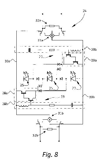
[0093] Figure 8 depicts a more detailed representation of the arrangement of
Figure 6, with
the groups 25, 26 and 27 of LEDs represented as a single LED symbol for
simplicity. The
embodiment shown in Figure 8 comprises two configuration switches 28 and 29,
which each
comprise a transistor switch 28a,29a and a frequency detection circuit 28b,
29b. The switches
28a, 29a can comprise, for example, simple transistor switches, Darlington
switches and
charge pump driven transistors, relays and/or other types of electromechanical
switches. The
frequency detection circuits 28b, 29b distinguish between a magnetic ballast
and an
electronic ballast and provide an appropriate input to control the switches
28a, 29a. A simple
CA 02925399 2016-03-24
WO 2015/044311
PCT/EP2014/070568
-20-
implementation of the frequency detection circuits 28b, 29b is a filter, such
as an inductor,
resistor, capacitor circuit as shown in Figure 8, an active filter, an any
circuit which can
generate an output which discriminates between a high frequency (e.g. from an
electronic
ballast) and a low frequency (e.g. from a magnetic ballast).
[0094] Reference is made here to the below table, comprising an example of
results for a
magnetic ballast and an electronic ballast, both with a fluorescent lamp and
an arrangement
according to the invention.
Table 2.1
Magnetic ballast Electronic ballast
Fluorescent tube LEDs Fluorescent tube LEDs
Absorbed power 36 28 40 31
Power factor 0.42 0.82 0.98 0.96
Reactive power 49 6 1 1
Apparent power 61 29 40 31
[0095] With respect to selection of the number of LEDs in each group and
composition of
the group, and number of LEDs the total string, the following is noted in
addition to the
above description.
[0096] At a start of a design process, one or more LEDs are selected having
characteristics
desired for the design determined in view of considerations known to the
skilled person. An
analytical model is created of the selected LED. Such a model can be as
complicated as
desired, but a simple linear model comprising an ideal diode to represent the
asymmetric V-I
(volt-to-current) characteristic, a voltage source to represent the forward
voltage of the LED,
and a resistor to represent the series resistance of the LED is sufficient in
most cases. An
analytical model is also created of the magnetic ballast. The dominant
characteristic of a
magnetic ballast is that of an inductor and the simplest model would be that
of an ideal
inductor having the same inductance as the ballast (determined at the
operating frequency).
[0097] These two models can be combined into one model and this model can be
analysed
either mathematically or analytically to yield a relationship between a number
of LEDs and
the power absorbed by these LEDs. The complexity and accuracy of this
relationship are
CA 02925399 2016-03-24
WO 2015/044311 PCT/EP2014/070568
-21-
expected to depend on the complexity and accuracy of the models chosen to
determine this
relationship, the range in which the models have been linearized and the
method of finding
the relationship. At this point in the design process the accuracy of the
model of the system
may be checked with empirical tests using the selected LEDs and the models
adjusted if
necessary.
[0098] Next, the electronic ballast needs to be modelled. The main problem
encountered
when modelling an electronic ballast is the complexity of electronic ballasts
and the large
spread in driving mechanisms between different brands and types of electronic
ballasts. One
approach is to measure and characterize a reference electronic ballast from a
predetermined
set up or operation point for a particular type of fluorescent tube, for
instance on the basis of
an IEC specification of fluorescent tube which is to be replaced. This may
then be linearized,
converted into a model and combined with the LED model. Thereafter, in much
the same
way as with the magnetic ballast, a relationship between the number of LEDs
and the power
may be deduced.
[0099] This process may be repeated for several numbers of parallel LED
strings of equal or
different length, considering that more LEDs in parallel connection imply
fewer LEDs in
series connection and, therefore, lower power.
[00100] All relationships are then plotted in a single graph, yielding a set
of curves such as
depicted in Figure 11 (the shape of the curves and values will vary depending
on many
factors such as type and wattage of the ballasts, type and temperature of the
LEDs, supply
voltage and frequency, and the like). The curves show power along the vertical
axis plotted
against the total forward voltage of an LED string driven by the ballast along
the horizontal
axis. Curve A shown in Figure 11 shows a modelled characteristic for a
magnetic ballast
driving the LED string composed of the selected type of LEDs arranged in a
circuit
configuration having a certain number of LEDs connected in series and parallel
to achieve a
certain forward voltage for the LED string. Curves B to E show modelled
characteristics for
an electronic ballast, for multiple variations of the circuit configuration of
the LED string
composed of the selected type of LED but having variable numbers of LEDs
connected in
series and parallel. Curve F the change to curve A for a magnetic ballast when
line regulation
is used as described herein.
CA 02925399 2016-03-24
WO 2015/044311 PCT/EP2014/070568
-22-
[00101] It is considered desirable in most circumstances to design the LED
lamp
arrangement to have equal power consumed when used with both magnetic and
electronic
ballasts. Thus, the optimal operating points are considered to be most
appropriately chosen at
intersections of the relevant curves. These intersections are however only
theoretical
operating points as they rarely intersect on whole numbers of LEDs (i.e. a
positive integer)
included in the LED string. For example, when the LED string comprises groups
of LEDs
which are switched between a series connection and a parallel connection, the
number of
parallel groups of LEDs (e.g. for electronic ballast operation) is preferably
the same as the
number of series groups of LEDs (e.g. for magnetic ballast operation).
[00102] To have the LED lamp arrangement operate at other powers or to have
the different
circuit configurations of the LED lamp arrangement operate at powers closer
together, the
characteristics will have to be shifted in such a way that the intersections
are on or near the
desired points. To achieve this, an embodiment which includes line regulation
means is
subsequently disclosed herein, in which an offset effectively shifts the whole
voltage/power
curve of the LED string or group on a magnetic ballast up, which can be
accomplished by
selecting the duty cycle of the switching means at a chosen mains voltage. The
LED power is
then increased for each point on the graph and the intersection can be shifted
to any power
level (albeit still limited to integer LED values in the electronic ballasted
configuration)
[00103] A method for determining a total number of LEDs in the LED string is
described
below. First, the number of parallel LED groups is determined by choosing the
electronic
ballast curve that intersects with the magnetic ballast characteristic closest
to, but always
below the desired power. The length of the substring in each parallel group is
then chosen by
picking the number of LEDs that result in a power, on the previously mentioned
electronic
ballast curve, that is closest to the desired power. The offset of the line
regulation means is
then chosen so that the characteristic of the magnetic ballast is shifted up
so that power output
for the number of LEDs resulting from a multiplication of the number of groups
with the
number of LEDs per group is either equal to the power of the electronic
ballast or to the
desired power, depending on design preference.
Line regulation and synchronous switching
[00104] Electronic ballasts are typically designed to actively control output
current and
output power and compensate for variations in voltage of the AC mains power
supply.
CA 02925399 2016-03-24
WO 2015/044311 PCT/EP2014/070568
-23-
Magnetic ballasts generally do not provide such compensation, and lamps
(fluorescent or
LED) connected to such a ballast will exhibit varying power consumption and
varying light
output in response to these variations in AC mains voltage.
[0100] To compensate for these variations in the power supply voltage, the LED
lamp
arrangement may include a line regulation circuit or device. For such
embodiment, the
voltage/power curve of the magnetic ballast is not modelled at nominal AC
mains voltage
(e.g. 220VAC) but at the maximum expected AC mains voltage value taking into
account the
maximum permitted deviation in voltage (e.g. 220 VAC + 10% maximum deviation).
In this
manner, all AC mains voltage values below that maximum value (including the
nominal and
minimum expected AC mains voltage values) will result in power consumption by
the LEDs
in the lamp below the desired maximum output, which may then be increased in
the manner
described below.
[0101] The alternating voltage of the AC mains power supply in combination
with the
nearly static forward voltage of the LEDs causes a time period during which
the input current
to the luminaire is essentially zero. This is illustrated in Figure 12, which
shows an
oscilloscope measurement of an input voltage to a magnetic ballast and output
current from a
magnetic ballast in a luminaire fitted with a conventional fluorescent tube.
As can be seen,
the output current waveform exhibits a small time period of zero or nearly
zero current
(referred to hereafter as the zero-current period). This zero-current period
occurs when the
voltage applied across the LEDs, e.g. the voltage on power supply lines 30a,
30b, falls below
the load voltage of the LEDs, which in normal operation amounts to the total
forward voltage
of the LED string. Where the luminaire includes a full-wave rectifier, this
zero-current period
occurs twice in each mains voltage cycle, e.g. at 100 Hz or 120 Hz.
[0102] A magnetic ballast effectively shortens this zero-current period due to
its inductance,
but in most practical configurations the period remains, ending at the moment
the
instantaneous AC mains voltage rises above the load voltage of the
arrangement. The LED
lamp arrangement may optionally include means for lowering the load voltage
during the
zero-current period to further reduce the length of the zero-current time
period.
[0103] In an exemplary embodiment, the circuit configuration of the LEDs can
be changed,
for example by bypassing (shorting) or disconnecting one or more of the LED
groups, or by
switching one or more of the LED groups into a parallel configuration in
parallel with one or
CA 02925399 2016-03-24
WO 2015/044311 PCT/EP2014/070568
-24-
more other LED groups, during at least a portion of the zero-current period.
This lowers the
load voltage (i.e. the forward voltage across the LED string) with respect to
the instantaneous
voltage at the input to the ballast, which reduces the time needed for the
instantaneous supply
voltage to exceed the load voltage so that current flows again through the
LEDs.
[0104] The circuit configuration of the LEDs can be changed using a dedicated
controlled
switch, or using one or more of the LED circuit configuration switches, to
reduce the load
voltage. This switch, from a circuit configuration with a higher load voltage
to a circuit
configuration with a lower load voltage, increases the instantaneous voltage
across the
magnetic ballast which leads to a faster rise of the current through the LEDs.
The time
interval with essentially zero current is shortened and the power factor is
increased. The
average or RMS current supplied to the LEDs can be controlled by varying the
time when the
circuit configuration is switched to the low load voltage. The switch to the
low load voltage
configuration may be accomplished by feed forward compensation based on input
voltage or
closed loop regulation based on the actual, measured LED current.
[0105] An exemplary embodiment according to this aspect of the invention is
depicted in
Figure 7. In this embodiment, control circuit 34 senses current flow through
the LEDs and
controls switch 28 on the basis of this current. In this embodiment, control
circuit 34 senses
current flowing through one or more of the groups of LEDs 25, 26, 27 by
sensing voltage
across impedance 33 through which the LED current flows. In this embodiment,
control
circuit 34 also receives two inputs, one input indicating the sensed current
and a second input
from a frequency detector 35. Control circuit 34 may be adapted to close
switch 28 when the
control circuit 34 receives both an input from frequency detector 35
indicating a frequency in
the range expected for a magnetic ballast, and an input indicating sensed LED
current is
below a threshold, e.g. zero or nearly zero.
[0106] In this embodiment, switch 29 is controlled by an input from frequency
detector 35,
and remains open when frequency detector 35 indicates an electronic ballast is
used and
remains closed when frequency detector 35 indicates a magnetic ballast is
used.
[0107] For example, line regulation may be enabled during magnetic ballast
operation in
which switch 29 is closed, producing e.g. a magnetic ballast circuit
configuration. When
switch 28 is open, LED groups 27 and 26 are connected in parallel, and the LED
group 25 is
in series with the combination of LED groups 26 and 27. In that configuration,
the total LED
CA 02925399 2016-03-24
WO 2015/044311 PCT/EP2014/070568
-25 -
voltage drop is twice the total LED voltage drop of one of the single LED
groups. Closing of
the switch 28 results in all LED groups (25, 26, and 27) being connected in
parallel, which
effectively reduces the total LED voltage drop to the total voltage drop of a
single LED
group. Thus, closing of the switch 28 results in lowering of the voltage at
the LED load, and,
as explained above, this reduction causes an increase in the ballast voltage
which produces
the faster rise in current. In the shown embodiment, the switch 28 is a switch
solely dedicated
to line regulation. Alternatively, one or more of the switches that are used
for changing the
circuit configuration, as described above in relation to the Figure 5
embodiment, can be
configured to further operate as line regulation switches.
[0108] Because of the low switching frequency, typically 100 or 120Hz, used
for thie line
regulation, there is little electromagnetic interference at radio frequencies.
[0109] Losses of the magnetic ballast are also slightly reduced compared to
operation with
standard fluorescent tubes. The smaller difference between the LED voltage
drop in the
arrangement and the AC mains voltage reduces the Volt x Seconds product on the
magnetic
ballast inductor (i.e. saturation of the inductor takes longer) and thus
slightly reduces the
magnetizing losses. The smaller RMS or average current also leads to slightly
reduced
resistive losses. Greater overall efficiency and lower operating temperature,
which increases
the ballast's lifetime, are further advantages of this embodiment. Results of
measurements of
a practiced embodiment according to this aspect of the invention, and a
fluorescent tube at
comparable light levels are shown in the following table:
Table 3.1
Input power Ballast loss Power factor
(W) (W)
T8 fluorescent Tube with
64.0 9.8 0.48
magnetic ballast
LED arrangement without
39.0 1.2 0.82
line regulation means
LED arrangement with line
39.0 1.1 0.93
regulation means
[0110] Figures 13 and 14 show the improvement of the voltage and current
waveforms
obtained by using line regulation (also referred to as synchronous switching)
according to this
embodiment. Figure 13 shows the input voltage 52, input current 53, current 54
through the
CA 02925399 2016-03-24
WO 2015/044311 PCT/EP2014/070568
-26-
LEDs, and current 55 through the switch 28, for non-switched operation. Figure
14 shows the
input voltage 56, input current 57, current 58 through the LEDs, and current
59 through
switch 28, for synchronous switched operation (i.e. switching the controlled
switch
simultaneously with the zero current period) at the same LED power level.
Flicker reduction
[0111] Because both the electronic and magnetic ballasts output alternating
current, the
LEDs powered by these ballasts are continually cycled on and off, causing the
LEDs to
flicker. Electronic ballasts operate at high frequencies (usually in excess of
20 kHz) and this
flicker falls outside the sensitivity range of the human eye. Magnetic
ballasts operate at mains
frequency (usually 50 or 60 Hz) and when a full-wave rectifier is used the
LEDs flicker at
twice that frequency. This flicker is perceptible to the human eye and for
this and other
reasons is highly undesirable. According to a further optional aspect of the
invention, the
LED arrangement may include means to reduce or eliminate this flicker.
[0112] This may be effected by directing part of the electrical energy from
the power
supplied to the LED arrangement away from the LEDs into a storage element
during at least
part of the period of peak light output from the LEDs, and directing part of
the stored
electrical energy back from the storage element to the LEDs during at least
part of the period
of low light output from the LEDs. This effectively reduces flicker by
averaging the peaks
and valleys in light output. Storing and retrieving only part of the energy
supplied to the
LEDs greatly improves efficiency compared to doing so for all the energy
supplied to the
LEDs.
[0113] An exemplary embodiment is illustrated in Figure 9, which shows a
portion of the
LED lamp arrangement described in previous embodiments with the addition of a
control
circuit 37 controls a switch 36 to effect storage and retrieval of energy into
and out from
energy storage element 39.
[0114] In this embodiment the control circuit 37 senses the current flowing
through at least
a portion of the LEDs and controls switch 36 on the basis of the sensed
current. In this
embodiment, control circuit 37 senses current flowing through one or more of
the groups of
LEDs 25, 26, 27 by sensing voltage across resistor 38 through which the LED
current flows.
Control circuit 37 controls switch 36 to selectively connect energy storage
element 39 to the
CA 02925399 2016-03-24
WO 2015/044311 PCT/EP2014/070568
-27-
power supply to the LEDs. In this embodiment, closing switch 36 connects
energy storage
element 39 across the power supply to the LEDs (i.e. the output lines 30a, 30b
from rectifiers
31a, 31b shown in Figs. 5-8) so that current flows into the energy storage
element 39.
[0115] Control circuit 37 is configured to close switch 36 when the sensed
current rises
above a first predetermined threshold, and open switch 36 when the sensed
current falls
below a second predetermined threshold (which may be equal to the first
predetermined
threshold) to disconnect energy storage element 39. Current through the LEDs
generally
varies according to the (full-wave rectified) AC voltage of the power supply
to the LEDs. The
first and second predetermined thresholds are set so that energy is stored in
energy storage
element 39 during peaks in each cycle of the alternating current through (a
portion of) the
LEDs. When the sensed current falls below a third predetermined threshold the
control circuit
37 closes switch 36 again to connect energy storage element 39 across the
power supply lines
and across the LEDs, and when the sensed current rises above a fourth
predetermined
threshold (which may be equal to the third predetermined threshold) the
control circuit 37
opens switch 36 to once again disconnect energy storage element 39. The third
and fourth
predetermined thresholds are set so that energy storage element 39 is
connected across the
LEDs to release the stored energy during valleys in each cycle of the
alternating current
through (a portion of) the LEDs.
[0116] The control circuit 37 may be implemented as one or more comparator
circuits or
may comprise more complex logic implemented in hardwired circuits or circuits
or processor
using firmware of software. Switch 36 may be implemented as a simple
transistor switch or
more complex switching or variable impedance circuit. Energy storage element
39 may be
implemented as a simple capacitor or circuit element capable of storing
electrical energy.
Control circuit 37 may sense current through all or a portion of the LEDs,
using a simple
resistor as described in the embodiment of Figure 9 or other circuit
arrangement for sensing
current. Control circuit 37 may alternatively be arranged to sense voltage of
the power supply
or across all or a portion of the LEDs, or sense phase of the cycle of the
alternating current or
voltage.
[0117] In some embodiments, the first and second configuration switches
(depicted as
switches 28 and 29 in Figure 9) may also or alternatively be closed to draw
current from the
energy storage element into the LEDs.
CA 02925399 2016-03-24
WO 2015/044311 PCT/EP2014/070568
-28-
[0118] The control circuit 37 may also include frequency detection means or be
configured
to receive input from a separate frequency detection circuit, e.g. as
described for the
embodiments shown in Figures 5, 6, 8, so that, for example, the energy storage
means is
enabled based on the type of ballast detected. In an exemplary embodiment, the
control
circuit 37 is configured so that the energy storage circuit is only enabled
when a magnetic
ballast has been detected.
Starter removal
[0119] In a further embodiment the LED lamp arrangement is optionally provided
with
means to render unnecessary the removal of a starter from a fluorescent
luminaire. A starter is
normally used to ignite a fluorescent tube when used with a magnetic ballast.
The starter
usually consists of a switch, either mechanical or electrical, that
periodically short-circuits the
magnetic ballast to the mains in series with the heater coils in the ends of
the fluorescent tube.
After the fluorescent lamp ignites, the voltage across the starter drops below
a certain voltage
impeding the starter from operation and further short-circuiting the lamp.
[0120] Because the LED lamp arrangement operates at considerably higher
voltage than the
fluorescent tube it replaces, the starter, which is configured to be
automatically enabled by
the higher voltage during the initial power-up period before the current has
risen to its normal
operational value, will continue to periodically short-circuit the filaments
of the lamp to the
ballast, causing undesirable low-frequency flicker.
[0121] The starter may be removed from the luminaire to prevent this from
happening, but
failure of the end-user to do so may result in unsafe situations and
destruction of the LED
lamp arrangement. Another solution is to place a high impedance element across
the pins of
the LED lamp arrangement, i.e. where the heater coils are located in a
fluorescent tube, with
an impedance sufficiently high to prevent the starter from detecting the high
voltage on the
other side of the tube. This solution, however, will cause some electronic
ballasts to
wrongfully detect the end of life of the tube, causing it to shut down.
[0122] To address this problem, a further embodiment of the LED lamp
arrangement may
optionally include a variable impedance connected across the connectors of the
LED lamp
arrangement, e.g. the pins for connecting the LED lamp arrangement into a
conventional
fluorescent luminaire in the location usually used for a heater coil in a
fluorescent tube. The
CA 02925399 2016-03-24
WO 2015/044311 PCT/EP2014/070568
-29-
presence of either a magnetic or an electronic ballast in the system is
detected, and the
variable impedance is adjusted to a high or a low impedance value depending on
the detected
type of ballast. An exemplary embodiment is depicted in Figure 10, in which
control circuit
43 controls a switch 42 to connect either a high impedance 41a or a low
impedance 41b
across the pin connectors 40a, 40b of the LED lamp arrangement. The variable
impedance
can be connected across one or both pairs of connectors present in the
luminaire.
[0123] Further modifications in addition to those described above may be made
to the
structures and techniques described herein without departing from the spirit
and scope of the
invention. Accordingly, although specific embodiments have been described,
these are
examples only and are not limiting upon the scope of the invention.