Note: Descriptions are shown in the official language in which they were submitted.
CA 02925469 2016-03-24
WO 2015/065456 PCT/US2013/067874
CORRELATING ENERGY TO MIX CEMENT SLURRY UNDER DIFFERENT
MIXING CONDITIONS
TECHNICAL FIELD
[0001] This disclosure relates to mixing oil-well fluids, including but not
limited to
oil-well cement slurries.
BACKGROUND
[0002] Cement compositions may be used in a variety of subterranean
operations,
such as, in the production and exploration of hydrocarbons, e.g., oil, gas,
and other
hydrocarbons, onshore and offshore. For example, a subterranean well can be
constructed
using a pipe string (e.g., casing, liners, expandable tubulars, etc.), which
can be run into a
wellbore and cemented in place. The process of cementing the pipe string in
place is
commonly referred to as "primary cementing." In a typical primary cementing
method, a
cement composition can be pumped into an annulus between the walls of the
wellbore and
the exterior surface of the pipe string disposed therein. The cement
composition can set in
the annular space, thereby forming an annular sheath of hardened,
substantially impermeable
cement (i.e., a cement sheath). The cement sheath can support and position the
pipe string in
the wellbore and bond the exterior surface of the pipe string to the
subterranean formation.
The cement sheath surrounding the pipe string functions to prevent the
migration of fluids in
the annulus among other things, and to protect the pipe string from corrosion.
[0003] A broad variety of well cement compositions have been used in
subterranean
well cementing operations. Such well cement compositions can be made by mixing
portland
cement with water and often with one or more other additives such are
retarders,
accelerators, lightweight additives. The additives can be either dry powder,
or liquid or both.
The components are mixed under certain mixing conditions (e.g., mixing speeds,
mixing
times, and other conditions). For example, industry guideline specifications
for laboratory
experiments designed to mimic field operations, which include quantities and
mixing
conditions, for mixing a specified volume of a cement slurry are provided,
e.g., by
institutions such as the American Petroleum Institute (API) or other
institutions.
1
SUBSTITUTE SHEET (RULE 26)
[0004] A variety of mixing equipment are employed in the field to mix the
broad
variety of cement compositions. Examples of such mixing equipment include
batch mixers
and RCM Ilk Mixers (a Halliburton Energy Services Inc. mixing system).
Certain mixing
equipment, e.g., mixing equipment implemented under laboratory conditions, can
be used to
mix a specified volume of well cement slurry according to the industry
guideline
specifications (e.g., the API specifications). For example, the laboratory
mixing equipment
can mix the specified volume under API specifications such as specified time
and mixing
RPM. In some situations, additives are incorporated into the well cement
slurry or larger
volumes of slurry are mixed (or both). The energy consumed by the mixing
process in those
situations may exceed the energy consumed during mixing in other situations.
Capabilities
are available to modify the mixing equipment to provide the additional energy
to mix the well
cement slurry with the additives or the larger volumes of well cement slurry
(or both). The
mixing capabilities of different mixing equipment to mix well cement slurry
can differ. For
example, the capabilities of field equipment, i.e., equipment used at or near
a well site to mix
well cement slurry, can differ from the mixing capabilities of other
equipment, e.g., the
mixing equipment used under laboratory conditions. The difference in
capabilities can affect
the mixability of the well cement slurry under industry guideline
specifications or the quality
of the mixed well cement slurry (or both).
SUMMARY
[0004a] In accordance with a general aspect, there is provided a method
comprising:
measuring electrical power supplied to an electric mixer in mixing a specified
well cement
slurry and determining an energy to mix the specified well cement slurry from
the measuring;
comparing the energy to mix the specified well cement slurry with an energy
required to mix
the specified well cement slurry using field equipment for mixing the
specified well cement
at a well site, the field equipment being of a different configuration than
the electric mixer;
and determining based on the comparing, whether the well cement slurry needs
redesigning
to be mixable according to mixing capabilities of the field equipment;
identifying a
redesigned cement slurry specification that is mixable by the field equipment;
and operating
the field equipment according to the redesigned cement slurry specification to
achieve a
redesigned well cement slurry when the redesigned cement slurry specification
requires a
redesigning of the cement slurry.
[0004b] In accordance with another aspect, there is provided a system
comprising: an
electric mixer to mix a specified well cement slurry; a measurement device
connected to the
2
CA 2925469 2017-10-26
electric mixer to directly measure electrical power supplied to the mixer in
mixing the
specified well cement slurry; field equipment for mixing the specified well
cement slurry at a
well site, the field equipment being of a different configuration then the
electric mixer; a
computer system comprising: one or more processors; and a computer-readable
medium
storing instructions executable by the one or more processors to perform
operations
comprising: determining an energy to mix the specified well cement slurry from
the
measuring; comparing the energy to mix the specified well cement slurry with
an energy
required to mix the specified well cement slurry using the field equipment;
and comparing the
enemy to mix the specified well cement slurry with the energy to mix the
specified well
cement slurry at the well site, and determining, based on the comparing,
whether the well
cement slurry needs redesigning to be mixable according to mixing capabilities
of the field
equipment; and identifying a redesigned cement slurry specification that is
mixable by the
field equipment, wherein the field equipment is adapted to mix the specified
cement slurry
according to the redesigned cement slurry specification to achieve a
redesigned well cement
slurry.
DESCRIPTION OF DRAWINGS
[0005] FIG. I illustrates example conditions for mixing a well cement slurry.
[0006] FIG. 2 is a flowchart of an example process to correlate energy to mix
a
cement slurry under a first set of mixing conditions to a second set of mixing
conditions.
[0007] FIG. 3 illustrates a schematic of an example computer system of FIG. 1.
[0008] Like reference symbols in the various drawings indicate like elements.
2a
CA 2925469 2017-10-26
CA 02925469 2016-03-24
WO 2015/065456 PCT/US2013/067874
DETAILED DESCRIPTION
[0009] This disclosure relates to correlating the energy to mix well cement
slurries
under two different mixing conditions, each of which implements mixing
equipment having
different capabilities. The disclosure describes techniques to correlate a
process of mixing a
well cement slurry under industry guideline specifications, e.g., using
laboratory mixing
equipment to mixing the well cement slurry under the same or similar
specifications, e.g.,
using field mixing equipment. Well cement slurry is an example of cement
slurry to which
the techniques described here are applicable; the techniques are applicable to
other cement
slurries, e.g., non-well cement slurries. The wettability of the dry
components (such as the
portland cement and the dry additives used), and the difference in shear
history and mixing
energy between the mixing equipment implemented under laboratory conditions
and the field
equipment are some of the factors that affect the correlation. Correlating the
mixing under
the different mixing conditions can allow scaling the mixing process, e.g.,
from a smaller
scale such as that implemented using a small laboratory mixing equipment to a
larger scale
such as that implemented using relatively larger field mixing equipment.
[0010] Knowing an energy input to the mixing process can enable correlating a
mixing process implemented under a first set of mixing conditions, e.g.,
laboratory
conditions, with the process implemented under a second set of mixing
conditions, e.g., field
conditions, that are different from the first set. This disclosure describes
techniques to
directly measure the energy, e.g., as Mechanical Energy Input (MEI), during
mixing of a
cement slurry using a first type of mixing equipment, e.g., laboratory mixing
equipment, and
to correlate an order of magnitude MEI to mix the cement slurry using a second
type of
mixing equipment, e.g., field equipment, that has different mixing
capabilities relative to the
first type. Knowing the MEI during the mixing process can enable a
determination of the gap
between the industry guideline specifications and the field equipment mixing
capabilities.
The gap can be used to determine when a cement slurry will be mixable under
the second set
of mixing conditions, e.g., in the field based on the first set of mixing
conditions, e.g., the
laboratory mixing energy data. The techniques described here can decrease (or
eliminate) a
need to incorporate approximations into the operational procedure to evaluate
the energy
utilized in the mixing process. Relative to the approximation-based
techniques, the
quantitative techniques described here can be more direct and more reliable.
The direct
3
SUBSTITUTE SHEET (RULE 26)
CA 02925469 2016-03-24
WO 2015/065456 PCT/US2013/067874
measurement of energy instead of approximation can increase a portability of
the techniques
across environments that implement the first set of mixing conditions to
determine mixing
energy. The techniques described here also decreases or eliminate a need for
calibration and
any apriori determination of constants of approximation. Furthermore, the
techniques allow
for the potential decrease or elimination of the current disconnect between
blending
equipment of various sizes and geometries.
[0011] FIG. 1 illustrates example conditions for mixing a cement slurry. A
specified
cement slurry can be mixed under a first set of mixing conditions, e.g.,
laboratory conditions
in a laboratory environment 100. Under the first set of mixing conditions,
mixing equipment
of a first type can be implemented to mix a specified volume of cement slurry
under industry
guideline specifications. For example, the laboratory environment 100 can
include an electric
mixer 102 to mix the specified cement slurry under API specifications or other
industry
guideline specifications. The electric mixer 102 can include, e.g., mixing
blades 104
connected to a motor 106 to rotate the mixing blades 104. The electric mixer
102 can be
connected to a measurement device 108 to directly measure electrical power
supplied to the
mixer in mixing the specified cement slurry. In some implementations, the
measurement
device 108 can be a multimeter connected to the motor 106 to measure
parameters to
determine the electrical power, e.g., a voltage across the motor 106, a
current through the
motor 106, other parameters or combinations of them.
[0012] The measurement device 108 can be connected to a computer system 110
which includes one or more processors 112 and a computer-readable medium 114
storing
instructions executable by the one or more processors 112 to correlate the
mechanical energy
to mix the cement slurry under the laboratory conditions and under field
conditions. The
computer system 110 can include any computer, e.g., a desktop computer, a
laptop computer,
a smartphone, a tablet computer, a personal digital assistant (PDA) or other
computer. The
computer system 110 can be connected to one or more input devices 116 and one
or more
output devices 118. In some implementations, the computer system 110 can be
implemented
as hardware or firmware integrated into the measurement device 108.
Alternatively, or in
addition, the measurement device 108 can be integrated into the computer
system 110. In
some implementations, data from the measurement device 108 can be manually
input into the
computer system 110, e.g., using the one or more input devices 116.
4
SUBSTITUTE SHEET (RULE 26)
CA 02925469 2016-03-24
WO 2015/065456 PCT/US2013/067874
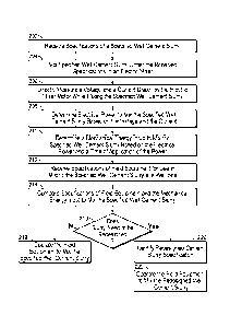
[0013] FIG. 2 is a flowchart of an example process 200 to correlate energy to
mix
cement slurry under a first set of mixing conditions, e.g., laboratory
conditions, to a second
set of mixing conditions, e.g., field conditions that are different from the
laboratory
conditions. In some implementations, at least a portion of the process 200 can
be
implemented by the electric mixer 102, the measurement device 108, the
computer system
110 or combinations of them. In some implementations, at least a portion of
the process 200
can be implemented by the electric mixer 102, the measurement device 108, an
operator, or
combinations of them. At 202, specifications of a specified cement slurry can
be received.
The specifications include a speed of mixing (e.g., a speed at which the
mixing blades 104
are to be rotated), a time of mixing (e.g., in minutes, hours, or other
times), a quantity of each
cement slurry component to be mixed, a quantity of water (or other fluid) to
be added to mix
the multiple components, a quantity of wetness or quantity of homogeneity of
the mixed
cement slurry, combinations of them, or other specifications. In certain
instances, the speed
and time of mixing, can be specified in the industry guideline specifications,
e.g., the API.
[0014] At 204, the components of the specified well cement slurry can be mixed
under the received specifications. To do so, respective quantities of
components of the
specified well cement slurry (e.g., hydraulic cement, water, additives, or
other components)
can be added to the electric mixer 102. In some implementations, dry additives
can also be
added to the liquids that comprise the specified well cement slurry. In one
example instance,
the motor 106 can be operated to rotate the mixing blades 104 at the speed of
mixing and for
the time of mixing to mix the multiple components to produce the specified
well cement
slurry. For example, mixing the components under the API specifications can
result in the
specified well cement slurry having the quantity of wetness or the quantity of
homogeneity
(or both) specified in the API specifications. Similarly, in other example
instances, the motor
106 can be operated to rotate the mixing blades 104 at respective (e.g.,
different) speeds of
mixing and for respective (e.g., different) times of mixing to mix the
multiple components to
produce the specified well cement slurry. In this manner, in multiple
instances of mixing,
well cement slurry can be mixed at different mixing speeds or different mixing
times or both.
SUBSTITUTE SHEET (RULE 26)
CA 02925469 2016-03-24
WO 2015/065456 PCT/US2013/067874
[0015] At 206, a voltage across and a current drawn by the electric mixer 102
can be
directly measured while mixing the specified well cement slurry. In some
implementations,
the measurement device 108 (e.g., the multimeter) can be directly connected to
the motor 106
to measure the voltage across and the current drawn by the motor 102 while
mixing. The
measurement device 108 can be implemented to obtain multiple measurements of
voltage and
current, each measurement corresponding to a respective instance of operating
the motor 106
at a mixing speed for a mixing time.
[0016] At 208, the energy to mix the specified well cement slurry can be
determined
based on the measured voltage and the current. In some implementations, the
measurement
device 108 can transmit the measured voltage and current to the computer
system 110, which
can implement computer operations to determine the electrical power, e.g., as
a product of
voltage and current. For example, the voltage and current can be measured for
a period of
time in the laboratory environment 100 under the laboratory conditions. The
electrical power
can be determined as a product of a time-averaged voltage and a time-averaged
current. For
the multiple instances of operating the motor 106, the computer system 110 can
determine
multiple values of electrical power, each value being a product of a
respective time-averaged
voltage and time-averaged current.
[0017] Upon measuring the electrical power supplied to the electric mixer 102,
the
energy to mix the specified well cement slurry from the measuring can be
determined at 210.
In some implementations, the energy can be electrical energy determined as a
product of
electrical power and the time of application of the electrical power. For
example, the
computer system 110 can determine a Mechanical Energy Input (MET) to mix the
specified
well cement slurry based on the electrical power using Equationl shown below.
ME 'mixer 0.00134 [(Vxf)xt]= (hp-min)
(Equation 1)
Volume -bbl
6
SUBSTITUTE SHEET (RULE 26)
CA 02925469 2016-03-24
WO 2015/065456 PCT/US2013/067874
[0018] In Equation 1, MEIniixer represents MEI when the well cement slurry is
mixed
under laboratory conditions, and V and [ represent voltage and current,
respectively, averaged
over the total mixing time, t. In some implementations, the functionality to
determine the
electrical power and the MET can be integrated into the measurement device
108. Also, the
computer system 110 can determine multiple MET values for the multiple
instances of mixing
described above.
[0019] At 212, specification of a second type of mixing equipment, e.g., field
equipment 122 for use in mixing the specified well cement slurry at a well
site 124 can be
received. The field equipment 122 can be of a different configuration than the
electric mixer
102. For example, the field equipment 122 can be a hydraulic mixer, a static
mixer, an
agitator system or other mixer that is different from the electric mixer 102.
An example of a
hydraulic mixer is the RCM Illr Mixer (a Halliburton Energy Sercives Inc.
mixing system).
The computer system 110 can receive the specifications of the hydraulic mixer,
which can
include a maximum pressure drop across the hydraulic mixer, a maximum
volumetric flow
rate of the hydraulic mixer, a maximum rotational speed of the hydraulic
mixer, combinations
of them, or other specifications.
[0020] In some implementations, the computer system 110 can determine, based
in
part on the specifications of the second type of equipment, a maximum energy
that the second
type of equipment can output to prepare the specified well cement slurry under
the second set
of mixing conditions, e.g., the field conditions, according to Equation 2.
[0021] For example, for a field equipment having a pressure drop and
volumetric
flow rate of AP and Q, respectively, the computer system 110 can determine an
MEI for the
field equipment 122 using Equation 2 shown below.
AP xQ (hp=min)
ME 'field equipment ¨(Equation 2)
Volume ¨ bbl )
[0022] Based on a comparison of the MEI of the field equipment 122, when
mixing
the well cement slurry under the industry guideline specifications in the
field environment
120, and the MEI for the electric mixer 102 to mix the well cement slurry
under the industry
guideline specifications in the laboratory environment 100, a determination is
made as to
whether or not the well cement slurry can be mixed using the field equipment
122, as
described below.
7
SUBSTITUTE SHEET (RULE 26)
CA 02925469 2016-03-24
WO 2015/065456 PCT/US2013/067874
[0023] At 214, the energy to mix the specified well cement slurry under the
first set of
mixing conditions, e.g., the laboratory conditions, and the specifications of
the second type of
equipment, e.g., the field equipment, can be compared. For example, the
computer system
110 can compare the MEI determined for the field equipment 122 using Equation
2, which
represents the maximum energy that the field equipment 122 can output, with
the MET
determined for the electric mixer 102 determined using Equation 1.
[0024] Based on the comparing, at 216, a check can be performed to determine
the
well cement slurry that was mixed using the first type of mixing equipment,
i.e., the
laboratory mixing equipment, can be used as-is with the second type of mixing
equipment,
i.e., the field equipment, or if the well cement slurry needs to be re-
designed. In the absence
of industry guideline specifications for mixing in the field and because
different mixing
equipment have different manufacturer-specified mixing properties, the
comparison of the
MEIs, as described above, can be beneficial to determine the applicability of
an available
field equipment to mix a well cement slurry. For example, based on the
comparing, the
computer system 110 or an operator (or both) can determines that the well
cement slurry can
be mixed as-is using the field equipment 122. The computer system 110 can
provide a
notification of the determination, e.g., in the output devices 116. In
response, at 218, the field
equipment 122 can be operated to mix the specified well cement slurry. For
example, an
operator can operate the field equipment 122 under the industry guideline
specifications to
mix the well cement slurry.
[0025] Instead, based on the comparison, the computer system 110 or the
operator (or
both) can determine that the well cement slurry needs to be re-designed to be
mixable by the
field equipment 122. The computer system 110 can provide a notification of the
determination, e.g., in the output devices 116. In response, at 220, the well
cement slurry can
be redesigned according to the specifications of the field equipment 122. For
example, the
well cement slurry can be redesigned to meet the specifications or mixing
capabilities (or
both) of the available field equipment.
8
SUBSTITUTE SHEET (RULE 26)
CA 02925469 2016-03-24
WO 2015/065456 PCT/US2013/067874
[0026] At 220, the second type of mixing equipment, e.g., the field equipment
can be
operated to mix the re-designed well cement slurry. In this manner, a direct
measurement of
MET from the electrical mixer 102 operated under laboratory conditions can be
correlated
with field equipment 122 to determine mixability of well cement slurry. In
particular, the
direct measurement decreases (or avoids) a need for approximation of constants
to determine
the energy consumed by the electrical mixer 102.
[0027] FIG. 3 illustrates a schematic of an example computer system 110 of
FIG. 1.
The computer system 110 can be connected to the first type of mixing equipment
that mixes
the well cement slurry under the first set of mixing conditions. For example,
the computer
system 110 can be located in the laboratory environment 100, i.e., an
environment in which
mixing under laboratory conditions can be recreated. The computer system 110
can include
one or more processors 112, a computer-readable medium 114 (e.g., a memory),
and
input/output controllers 302 communicably coupled by a bus. The computer-
readable
medium 114 can include, for example, a random access memory (RAM), a storage
device
(e.g., a writable read-only memory (ROM) and/or others), a hard disk, and/or
another type of
storage medium. The computer system 110 can be preprogrammed and/or it can be
programmed (and reprogrammed) by loading a program from another source (e.g.,
from a
CD-ROM, from another computer device through a data network, and/or in another
manner).
The input/output controller 302 is coupled to input/output devices (e.g., the
display device
116, input devices 118, and/or other input/output devices) and to a network
304. The
input/output devices receive and transmit data in analog or digital form over
communication
links such as a serial link, wireless link (e.g., infrared, radio frequency,
and/or others),
parallel link, and/or another type of link.
[0028] The network 304 can include any type of data communication network. For
example, the network 304 can include a wireless and/or a wired network, a
Local Area
Network (LAN), a Wide Area Network (WAN), a private network, a public network
(such as
the Internet), a WiFi network, a network that includes a satellite link,
and/or another type of
data communication network.
9
SUBSTITUTE SHEET (RULE 26)
CA 02925469 2016-03-24
WO 2015/065456 PCT/US2013/067874
100291 A number of implementations have been described. Nevertheless, it will
be
understood that various modifications may be made without departing from the
spirit and
scope of the disclosure.
SUBSTITUTE SHEET (RULE 26)