Note: Descriptions are shown in the official language in which they were submitted.
CA 02925508 2016-03-21
WO 2015/042721
PCT/CA2014/050931
HEAT EXCHANGER WITH INTEGRATED CO-AXIAL INLET/OUTLET TUBE
CROSS-REFERENCE TO RELATED APPLICATION
[0001] This application claims priority to and the benefit of United States
Provisional Patent Application No. 61/884,520 filed September 30, 2013, the
contents of which are incorporated herein by reference.
TECHNICAL FIELD
[0002] The invention relates to a heat exchanger, in particular a two-pass
heat exchanger having a co-axial inlet/outlet tube integrally mounted within
the
heat exchanger.
BACKGROUND
[0003] Two-pass or multi-pass heat exchangers are known wherein various
combinations of different heat exchanger plates are stacked together to create
the desired flow pattern through the heat exchanger. In a two-pass heat
exchanger, at least one of the fluid paths through the heat exchanger is
divided
into a first pass and a second pass, the first pass having an inlet manifold
for
introducing the fluid into the heat exchanger and an intermediate outlet
manifold
for transferring the fluid from the first pass and into the second pass, the
second
pass being in fluid communication with a further manifold that directs the
fluid
out of the heat exchanger after having completed the second pass. Accordingly,
three different manifold structures are required in order to create a two-pass
flow path, with one of the manifolds, i.e. the inlet manifold for one of the
fluids
in the heat exchanger, only extending through a portion of the heat exchanger
core. Therefore, in order to create a heat exchanger having the desired two-
pass flow pattern, different heat exchanger plates are required in order to
form
the heat exchanger core. Having a number of different plates required to form
a
heat exchanger increases costs associated with the heat exchanger and also
adds to the complexity associated with the manufacturing of the heat
exchanger.
Accordingly, it is desirable to modify a conventional, single-pass heat
exchanger
into a two-pass (or multi-pass heat exchanger) without requiring the use of
various different heat exchanger plates and without requiring an additional
manifold structure.
1
CA 02925508 2016-03-21
WO 2015/042721
PCT/CA2014/050931
SUMMARY OF THE PRESENT DISCLOSURE
[0004] In accordance with an example embodiment of the disclosure there
is provided a heat exchanger, comprising a plurality of stacked heat exchanger
plates defining a plurality of alternating first and second fluid channels
therebetween forming a heat exchanger core; a pair of first fluid manifolds
interconnected by the plurality of first fluid channels for inletting and
discharging
a first heat exchange fluid to and from the heat exchanger; a pair of second
fluid
manifolds interconnected by the plurality of second fluid channels for
inletting
and discharging a second heat exchanger fluid to and from the heat exchanger;
wherein one of said manifolds of said pair of either first or second fluid
manifolds
is an annular manifold structure having an annular first manifold fluid
passage
extending through a portion of the one of said manifolds in fluid
communication
with a first set of said first or second fluid passages; and a second manifold
fluid
passage extending centrally through said annular first manifold fluid passage
and fluidly isolated therefrom, the second manifold fluid passage being in
fluid
communication with a second set of said first or second fluid passages; the
annular manifold structure therefore inletting and discharging the same heat
exchange fluid to and from the heat exchanger core in a co-axial manner.
[0005] In accordance with another example embodiment of the present
disclosure there is provided a method of forming a two-pass heat exchanger
comprising providing a heat exchanger core comprising a plurality of spaced
apart heat exchanger plates defining a plurality of alternating first and
second
fluid channels therebetween; a pair of first fluid manifolds in communication
with
said plurality of first fluid channels for directing a first fluid through
said heat
exchanger; and a pair of second fluid manifolds in communication with said
second fluid channels for directing a second fluid through said heat
exchanger;
providing a manifold insert having an elongated, generally cylindrical body
extending between opposed first and second ends, the manifold insert having a
diameter less than the diameter of at least one of said manifolds in one of
said
pairs of manifolds; arranging said manifold insert within the at least one of
said
manifolds, the first end of said manifold insert being embedded within said
heat
exchanger and engaging one of said heat exchanger plates thereby dividing the
heat exchanger core into a first part and a second part, the second end of the
2
CA 02925508 2016-03-21
WO 2015/042721
PCT/CA2014/050931
manifold insert extending outwardly from the heat exchanger core; wherein the
manifold insert defines an annular first manifold fluid passage between the at
least one of said manifolds and the outer surface of said manifold insert, and
a
second manifold fluid passage within the open interior passage formed by the
cylindrical body, the annular first manifold fluid passage being in fluid
communication with the one of said plurality of first or second fluid channels
in
said first part, and wherein the second manifold fluid passage is in fluid
communication with the one of said plurality of first or second fluid channels
in
said second part.
[0006] In accordance with another example embodiment of the disclosure
there is provided a manifold insert for use in a heat exchanger having
corresponding pairs of internal manifolds formed therein, the respective pairs
of
manifolds coupled together by first and second fluid channels, the manifold
insert comprising an elongated generally cylindrical body defining an open
interior passage; a first end for sealingly engaging a portion of the interior
of
one of said manifolds and defining an annular first manifold flow passage
between the outer surface of said cylindrical body and the interior surface of
said
manifold, the first manifold flow passage being fluidly coupled to a portion
of
said first or second fluid channels; a second end extending out of said
manifold
for receiving a fluid fitting; and a second manifold flow passage defined by
said
open interior passage, the second manifold passage being fluidly coupled to a
remaining portion of said first or second fluid channels; wherein said
manifold
insert divides said heat exchanger into a first part and a second part, the
first
and second parts defining a two-pass flow path.
BRIEF DESCRIPTION OF THE DRAWINGS
[0007] Exemplary embodiments of the present disclosure will now be
described by way of example with reference to the accompanying drawings, in
which:
[0008] Figure 1 is a top, perspective view of a heat exchanger according
to an example embodiment of the present disclosure;
3
CA 02925508 2016-03-21
WO 2015/042721
PCT/CA2014/050931
[0009] Figure 2 is a cross-sectional view of the heat exchanger shown in
Figure 1 taken along section line 2-2;
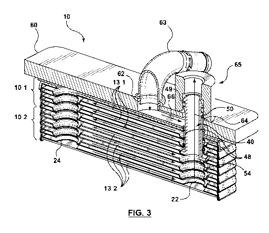
[0010] Figure 3 is a schematic cross-sectional view of the heat exchanger
as shown in Figure 2 illustrating the flow path of one of the fluids flowing
through the heat exchanger;
[0011] Figure 4 is a top, perspective view of one of the heat exchanger
plates forming the heat exchanger of Figure 1;
[0012] Figure 5 is a perspective view of a connection insert/tube for use
with the heat exchanger shown in Figure 1;
[0013] Figure 6 is a top, end view of the connection insert/tube of Figure
5;
[0014] Figure 7 is a cross-sectional view of the connection insert/tube
of
Figure 5 taken along section line 7-7;
[0015] Figure 8 is a detail view of a portion of the cross-section shown
in
Figure 2 and 3 showing the arrangement of the connection insert/tube within
the
heat exchanger;
[0016] Figure 9 is a detail view as shown in Figure 8 illustrating an
alternate embodiment of the connection insert/tube;
[0017] Figure 10 is a detail view as shown in Figure 8 illustrating
another
alternate embodiment of the connection insert/tube;
[0018] Figure 11 is a detail view as shown in Figure 8 illustrating yet
another alternate embodiment of the connection insert/tube;
[0019] Figure 12 is a schematic cross-sectional view of a two-pass heat
exchanger in accordance with principals known in the art illustrating the flow
path of one of the fluids flowing through the heat exchanger;
[0020] Figure 13 is a schematic cross-sectional view of the heat
exchanger shown in Figure 1 taken along section line 13-13 illustrating a
conventional flow path for a single pass heat exchanger design;
4
CA 02925508 2016-03-21
WO 2015/042721
PCT/CA2014/050931
[0021] Figure 14 is a top perspective view of the base plate of the heat
exchanger shown in Figure 1; and
[0022] Figure 15 is a bottom perspective view of the base plate of Figure
14.
DETAILED DESCRIPTION OF EXEMPLARY EMBODIMENTS
[0023] Reference will now be made in detail to exemplary implementations
of the technology. The example embodiments are provided by way of
explanation of the technology only and not as a limitation of the technology.
It
will be apparent to those skilled in the art that various modifications and
variations can be made in the present technology. Thus, it is intended that
the
present technology cover such modifications and variations that come within
the
scope of the present technology.
[0024] Referring now to Figure 1 there is shown an exemplary embodiment
of a heat exchanger 10 according to the present disclosure. Heat exchanger 10
is generally in the form of a nested, dished-plate heat exchanger. In the
specific
embodiment shown, heat exchanger 10 is comprised of a plurality of stamped
heat exchanger plates 12, 14 disposed in alternatingly, stacked, brazed
relation
to one another forming alternating first and second fluid channels or flow
passages 13, 15 therebetween. The heat exchanger plates 12, 14 are generally
identical to each other with each plate 12, 14 comprising a generally planar
base
portion 16 surrounded on all sides by a sloping, peripheral wall 18, as shown
in
Figure 4. Fluid openings 17, 19 are provided in each of the heat exchanger
plates 12, 14 to allow the inlet and outlet of respective first and second
heat
exchange fluids into the corresponding first and second fluid channels13, 15
of
the heat exchanger 10. Typically, each heat exchanger plate 12, 14 is provided
with four fluid openings strategically positioned within the boundary of the
base
portion 16 of the plates 12, 14, generally one in each of the four corners of
the
plates 12, 14. Two of the four fluid openings 17 are formed in embossments,
generally referred to as bosses or boss portions 20, that are raised (or
depressed) out of the plane of the central generally planar base portion 16 of
the
CA 02925508 2016-03-21
WO 2015/042721
PCT/CA2014/050931
plate 12, 14, while the other two fluid openings 19 in the plate 12, 14 are
formed in and are co-planar with the central, generally planar base portion 16
of
the plate 12, 14.
[0025] To form the heat exchanger core, heat exchanger plates 12, 14 are
stacked one on top of the other with one plate being rotated 180 degrees with
respect to the other in nesting arrangement such that the peripheral wall 18
of
one plate 12, 14 contacts and seals against the peripheral wall 18 of the
adjacent plate 12, 14, and so that the fluid openings 17 formed in the bosses
20
in one plate 12, 14 align with and seal against the flat or co-planar openings
19
of the adjacent plate 12, 14 thereby spacing apart the central base portions
16
of the adjacent plates 12, 14 and defining the alternating first and second
fluid
passages 13, 15 therebetween. When the plates 12, 14 are stacked so that the
peripheral wall 18 is downwardly depending with respect to the central base
portion 16, the boss portions 20 associated with two of the fluid openings 17
appear recessed or depressed with respect the central generally planar base
portion 16, as shown in Figure 4.
[0026] Turbulizers or any other suitable heat transfer augmentation device
27 (shown schematically in Figs. 8-11) may be arranged in the first and/or
second fluid channels 13, 15 of the heat exchanger 10 in order to increase
heat
transfer performance of the heat exchanger 10. Alternatively, the central
generally planar base portion 16 of the heat exchanger plates 12, 14 may be
provided with dimples, ribs, and/or protrusions in order to increase heat
transfer
performance across the heat exchanger in accordance with principles known in
the art.
[0027] The aligned fluid openings 17, 19 in the stacked plates 12, 14 form
a pair of first fluid manifolds 22, 24 (i.e. a first inlet manifold and a
first outlet
manifold) coupled together by the first fluid passages 13 for the flow of the
first
heat exchange fluid through the heat exchanger 10, and form a pair of second
fluid manifolds 26, 28 (i.e. a second inlet manifold and a second outlet
manifold)
coupled together by the second fluid passages 15 for the flow of a second
fluid
through the heat exchanger 10. For example, depending upon the particular
application, one of the first or second heat exchange fluids may be oil (i.e.
6
CA 02925508 2016-03-21
WO 2015/042721
PCT/CA2014/050931
engine oil or transmission oil) while the other heat exchange fluid may be any
suitable coolant, for instance, water. While features of the heat exchanger 10
may be described with reference to the first fluid and/or the first fluid
channels
13, it will be understood that the features are equally applicable to the
second
fluid and the second fluid channels 15, and/or vice versa.
[0028] Top and bottom end plates 30, 32 enclose the stack of heat
exchanger plates 12, 14 that form the heat exchanger core. Depending upon
the particular application and the desired locations of the inlet and outlet
fittings
63, 65, 67, 69 for the first and second heat exchange fluids entering/exiting
the
heat exchanger 10, the end plates 30, 32 are formed with or without fluid
openings to allow for suitable inlet and outlet fittings to be arranged on the
heat
exchanger 10. In the example embodiment shown, the bottom end plate 32 has
no fluid openings formed therein and is a solid plate structure that serves to
close or seal the end of the heat exchanger 10 since all of the inlet and
outlet
fittings 63, 65, 67, 69 are arranged on the top end of the heat exchanger 10.
The top end plate 30, therefore, is provided with appropriate fluid openings
for
providing fluid communication between the inlet and outlet fittings and the
corresponding inlet and outlet manifolds 26, 28 associated with one of the
second heat exchange fluid as will be described in further detail below.
[0029] In a conventional, single-pass heat exchanger, a first heat
exchange fluid would enter the heat exchanger 10 through inlet fitting 63. The
fluid would flow though the corresponding inlet manifold and through the
plurality of first fluid channels 13. The fluid would then flow through the
corresponding outlet manifold and exit the heat exchanger 10 through outlet
fitting 65. A second heat exchange fluid would enter the heat exchanger
through the second inlet fitting 67 and flow through the corresponding inlet
manifold 26 and through the plurality of second fluid channels 15. The second
heat exchange fluid would then flow through the corresponding outlet manifold
28 and exit the heat exchanger 10 through outlet fitting 69. The fluid path of
the
second heat exchange fluid flowing through the heat exchanger 10 is
schematically shown in Figure 13. It is sometimes desirable, however, to
increase performance of a heat exchanger by modifying the flow pattern through
7
CA 02925508 2016-03-21
WO 2015/042721
PCT/CA2014/050931
the heat exchanger for one or both of the fluids flowing therethrough to
create a
two-pass or multi-pass heat exchanger.
[0030] Therefore, in the subject embodiment a connection tube or manifold
insert 40 is provided in order to modify the flow pattern through the heat
exchanger 10 from a conventional single-pass heat exchanger to a two-pass
heat exchanger for at least one of the fluids flowing through the heat
exchanger
10. Referring now to Figures 2 and 3, the manifold insert 40 is arranged
within
one of the manifolds of one of the pairs of inlet/outlet manifolds of the heat
exchanger 10 and effectively divides the heat exchanger core into a first part
10(1) defining a first pass (i.e. fluid channels 13(1)) for one of the fluids
flowing
the heat exchanger core, and a second part 10(2) defining a second pass (i.e.
fluid channels 13(2)) for the same fluid through the heat exchanger core. For
ease of reference, the two-pass fluid path through heat exchanger 10 is
described in association with the "first" heat exchanger fluid flowing through
the
heat exchanger 10. However, it will be understood by those skilled in the art
that the features associated with the two-pass are equally applicable to the
"second" heat exchange fluid and that various flow patterns can be created for
one or both of the first and second heat exchange fluids flowing through the
heat
exchanger 10 based on the principles described herein.
[0031] The manifold insert 40 is in the form of a machined tube having an
elongated generally cylindrical body 42 extending between opposed first and
second ends 44, 46. The generally cylindrical body 42 has an outer diameter D1
that is less than the diameter of the fluid openings 17, 19 that form the
manifold
22 in which the insert 40 is arranged. The first end 44 of the manifold insert
40
is embedded within the associated fluid manifold 22, as shown for instance in
Figures 2 and 3, and serves to seal off a portion of the manifold 22 from the
flow
of first fluid (or second fluid) into the heat exchanger 10. The second end 46
of
the manifold insert 40 extends out of the heat exchanger 10, the second end 46
being adapted to receive or couple with an appropriate fluid fitting 63 and
serves
to allow fluid to both enter and exit the heat exchanger 10 through the same
manifold opening. The manifold insert 40, therefore, creates an annular header
within the fluid manifold 22 in the first part 10(1) of the heat exchanger
core by
providing an annular first manifold flow passage 48 formed by the gap between
8
CA 02925508 2016-03-21
WO 2015/042721
PCT/CA2014/050931
the outer surface (or outer diameter D1) of the cylindrical body 42 that forms
the insert 40 and the aligned edges of the fluid openings 17, 19 that form the
manifold 22, and a second manifold flow passage 50 defined by the central,
internal passage defined by the cylindrical body 42 of the insert 40. The
annular
first manifold flow passage 48 formed by the manifold insert 40 is in fluid
communication with the first fluid channels 13 formed by plates 12, 14 within
the first part 10(1) of the heat exchanger core, i.e. first fluid channels
13(1), as
shown schematically by the flow arrows included in Figure 3, while the second
manifold flow passage 50 formed by the manifold insert 40 is fluidly coupled
to
the plurality of first fluid channels 13 formed by plates 12, 14 in the second
part
10(2) of the heat exchanger core, i.e. first fluid channels 13(2), as shown
schematically by the flow arrows included in Figure 3. Therefore, in the
subject
embodiment, at least one of the first and second fluids flowing through the
heat
exchanger 10 enters and exits the heat exchanger through the same manifold
structure, the heat exchanger 10 therefore having a co-axial inlet/outlet
manifold formed therein.
[0032] In the example embodiment shown primarily in Figures 1-8, the
first end 44 of the manifold insert 40 is in the form of a flanged end wherein
a
flange 54 of material extends radially outwardly from and encircles the open
end
56 of the cylindrical body 42. The flange 54 extends radially outwardly from
the
open end 56 of the cylindrical body so that the overall diameter D2 of the
flanged first end 44 is greater than the diameter of the aligned fluid
openings
17, 19 that form manifold 22. The flange 54, therefore, provides a bottom
surface 57 that abuts and/or rests against the lip of material 58 that
surrounds
the fluid opening 17 formed by the raised boss portions 20, as shown in Figure
8. The flange 54, therefore, effectively seals the end of the annular first
manifold flow passage 48 formed by the manifold insert 40. By sealing the end
of the first manifold flow passage 48, fluid that enters the first fluid
passage 48
travels through the manifold 22 only so far as the sealing first end 44 of the
manifold insert 40 and then travels through the first fluid channels 13(1)
formed
by the stacked plates 12, 14 that are in fluid communication with the annular
fluid passage 48. The fluid, therefore, travels through the annular inlet
passage
48, through the first fluid channels 13(1) in the first part 10(1) of the heat
9
CA 02925508 2016-03-21
WO 2015/042721
PCT/CA2014/050931
exchanger core to the corresponding fluid manifold 24 at the opposed end of
the
heat exchanger 10. The fluid then travels from the first part 10(1) of the
heat
exchanger 10 into the second part 10(2) of the heat exchanger 12 by means of
manifold 24 and travels through corresponding first fluid channels 13(2) in
the
second part 10(2) of the heat exchanger 10 in the opposite direction to the
direction of flow in the first part 10(1), thereby creating a second pass of
the
fluid through the heat exchanger 10. Once the fluid has completed the second
pass through fluid channels 13(2) in the second part 10(2) of the heat
exchanger 10, the fluid exits the heat exchanger 10 via the portion of
manifold
22 in the second part 10(2) of the heat exchanger and through the second
manifold flow passage 50 formed by the central passage through the manifold
insert 40 and is directed elsewhere in the overall system through the
appropriate
fluid outlet fitting 65. The second end 46 of the manifold insert 40 is
adapted to
sealingly engage with an appropriate fluid outlet fitting 65 for directing the
fluid
away from the heat exchanger 10, the manifold insert 40 and outlet fitting
form
a fluid tight connection therebetween. In some embodiments, the second end
46 of the manifold insert 40 is formed with at least one groove 47 in the
outer
surface thereof for receiving any suitable sealing means, such as an 0-ring,
49
for sealing against the inner surface of the fitting 65, see for instance
Figure 2.
[0033] An adapter or base plate 60 is arranged at one end of the heat
exchanger 10 in abutting relationship to either the top or bottom end plate
30,
32, depending upon the location of the fluid inlet/outlet fittings 63, 65, 67,
69.
In the embodiment shown in Figure 1, the base plate 60 is arranged at the top
end of the heat exchanger 10 and therefore is positioned on top of end plate
30.
An intermediate shim plate 61 may be positioned between the end plate 30 and
base plate 60 for attaching the two components together when the entire
assembly is brazed together to form the heat exchanger 10. The base plate 60
is
generally thicker than the plurality of heat exchanger plates 12, 14 that form
the
heat exchanger core and generally extends beyond the footprint defined by the
heat exchanger 10 to provide sufficient area around the periphery of the heat
exchanger 10 to allow for mounting holes to be provided at required locations,
if
necessary. The base plate 60 also has appropriate fluid openings formed
therein
so as to provide fluid communication between the various fluid inlet/outlet
CA 02925508 2016-03-21
WO 2015/042721
PCT/CA2014/050931
fittings 63, 65, 67, 69 that are provided and the corresponding inlet and
outlet
manifolds 22, 24, 26, 28 for each of the first and second heat exchange
fluids.
More specifically, in the subject embodiment two fluid openings 62, 64 are
formed in the base plate 60 so as to provide fluid communication between the
corresponding fluid inlet/outlet fittings 63, 65 and the corresponding heat
exchanger manifolds 22, 24 for the first fluid, and two fluid openings 71, 72
are
formed in the base plate 60 to provide fluid communication between the
corresponding fluid inlet/outlet fittings 67, 69 and the corresponding heat
exchanger manifolds 26, 28 for the second fluid.
[0034] In the subject embodiment, since one manifold (i.e. manifold 22)
acts as both the inlet manifold and the outlet manifold for one of the fluids
flowing through the heat exchanger as a result of the manifold insert 40, a
fluid
transfer channel 66 is provided in base plate 60 which directs fluid entering
the
heat exchanger 10 through inlet fitting 63 and opening 62 to the open end of
the
annular fluid inlet passage 48 formed by the manifold insert 40 (see Figure
3).
Opening 64 in the base plate 60 is adapted to receive the second end 46 of the
manifold insert 40 for establishing fluid communication between the open
second
end 44 of the manifold insert 40 and the corresponding outlet fitting 65. A
second fluid transfer channel 75 is formed in base plate 60 for directing the
second heat exchange fluid from outlet manifold 28 to the corresponding outlet
fitting 69, as shown in Figure 15. It will be understood, however, that the
structure of the base plate 60 and the number/location of fluid openings and
fluid transfer channels provided may vary depending upon the desired location
of
the inlet/outlet fittings.
[0035] While individual inlet and outlet fittings 63, 65 have been shown,
it
will be understood that any suitable fitting may be used to direct fluids into
and
out of the heat exchanger 10. For instance, in some embodiments, a combined
inlet/outlet fitting may be used wherein the fitting itself incorporates fluid
inlet
and fluid outlet passageways that communicate with the corresponding fluid
manifolds in the heat exchanger 10.
[0036] Referring now to Figures 8-11, various alternate embodiments of
the manifold insert 40 will be described in further detail. Figure 8 shows a
detail
11
CA 02925508 2016-03-21
WO 2015/042721
PCT/CA2014/050931
view of the first end 44 of the manifold insert 40 described above in
connection
with Figures 1-7. As shown, flange 54 surrounds the open first end 44 of the
manifold insert 40, the bottom surface 57 of which sits or rest on lip 58 of
material that surrounds fluid opening 17 in the formed bosses 20 of the plates
12, 14. The surface contact between the bottom surface 57 of the flange 54
provides adequate contact to ensure that the manifold insert 40 and heat
exchanger plates 12, 14 are fixed or sealed together by brazing or any other
suitable means.
[0037] Figure 9 shows an alternate embodiment of the manifold insert 40
wherein the manifold insert 40 is arranged so that the upper surface 59 of the
flange 54 contacts and is in abutting relationship with the portion of the
central
generally planar base portion 16 of the plate 12, 14, that surrounds the flat
fluid
openings 19. A machined cap or collar 70 is positioned on the manifold insert
40
at the first end 44 thereof, the collar 70 being sized to have an interference
or
fluid tight fit around the first end 44 of the manifold insert 40. The collar
70 is
formed with a flanged base 72 which rests on and is affixed to the lip 58 of
material surrounding the fluid opening 17 in the bosses 20. Therefore, when
the
heat exchanger 10 is assembled, the aligned fluid openings 17, 19 of one of
the
plate pairs 12, 14 are effectively sandwiched between the flanged base 72 of
the
collar 70 and the flanged first end 44 of the manifold insert 40.
[0038] Figure 10 illustrates yet another embodiment of the manifold insert
40 wherein the first end 44 of the insert 40 is formed with a circumferential
bead
74 that projects radially outwardly from the outer surface of the cylindrical
body
42, the bead 74 being slightly spaced apart from the open first end 44 of the
manifold insert 40. When the manifold insert 40 is arranged within a portion
of
the manifold 22, the circumferential bead engages and rests on the lip 58 of
material surrounding the fluid opening 17 in the boss portion 20, the end of
the
manifold insert 40 extending into the fluid opening 17 so that it can be
flared
outwards thereby creating a flanged end 54. As a result, the mating edges of
the aligned fluid openings 17, 19 of the plate pair 12, 14 that divides the
heat
exchanger core into the first part 10(1) and the second part 10(2) are
sandwiched between the upper surface 59 of the flanged end 54 and the
circumferential bead 74. By having the mating edges of the aligned fluid
12
CA 02925508 2016-03-21
WO 2015/042721
PCT/CA2014/050931
openings 17, 19 sandwiched between the flange 54 and the circumferential bead
74, two contact surfaces are provided for fixing and/or sealing the components
together, for instance, by brazing.
[0039] Figure 11 illustrates a further embodiment of the heat exchanger 10
wherein the manifold insert 10 is in the form of an elongated cylindrical tube
or
body 42. Rather than having a flange 54 formed at the first end of the
cylindrical body 42, a divider plate 76 is arranged within the stack of heat
exchanger plates 12, 14 and cooperates with the first end 44 of the manifold
insert 40 to divide the heat exchanger 10 into the respective first and second
parts 10(1), 10(2). Divider plate 76 generally has the same form as heat
exchanger plates 12, 14 and has a central, generally planar base portion 16
surrounded by a downwardly sloping peripheral wall 18. Four fluid openings are
formed in the respective corners of the plate 76, two of which are formed in
the
bosses (not shown) that project out of the plane of the base portion 16 of the
plate 76 as in the case of heat exchange plates 12, 14. The other two fluid
openings 19 are formed within the plane of the base portion 16 of the plate 76
with one of fluid openings 19' being formed so as to have a smaller diameter
than the other fluid openings 17, 19 in the plate 76. The diameter of the
fluid
opening 19' generally corresponds to the inner diameter of the cylindrical
tube or
body 42 that forms the manifold insert 40. Fluid opening 19' also comprises a
raised circumferential edge 78 that extends away from the opening 19', the
circumferential edge 78 being received within the open first end 44 of the
manifold insert 40. The manifold insert 40 and fluid opening 19' are sized so
as
to create a fluid-tight seal between the two components when they are fixed
together.
[0040] Figure 12 illustrates a two-pass heat exchanger 100 in accordance
with principles known in the art. In order to achieve the multi-pass flow
pattern
through the heat exchanger 100, the heat exchanger 100 is comprised of a first
portion 100(1) and a second portion 100(2), each of which are comprised of a
plurality of stacked heat exchange plates 112(1), 114(1) and 112(2), 114(2).
The lower or second portion 100(2) of the heat exchanger is comprised of
plates
112(1), 114(1) which are similar in structure to the heat exchanger plates 12,
14 described above in connection with heat exchanger 10. The upper or first
13
CA 02925508 2016-03-21
WO 2015/042721
PCT/CA2014/050931
portion 100(1) of the heat exchanger is comprised of a different set of heat
exchange plates 112(1), 114(1) which are similar to the above-described heat
exchanger plates 12, 14, 112(2), 114(2) except that an additional fluid
opening
117 formed in an additional boss portion 120' that is arranged proximal to the
one of the other boss portions 20. Therefore, when heat exchange plates
112(1),
114(1) are stacked in their alternating relationship to form fluid channels
113(1), 115(1) therebetween, an additional manifold structure 222 is formed
adjacent to manifold structure 22. In the embodiment shown in Figure 12, the
additional manifold structure 222 serves as the inlet manifold for delivering
fluid
to the first fluid channels 113(1) in the first part 100(1) of the heat
exchanger
100. The fluid then travels through the first fluid channels 113(1) to the
corresponding manifold structure 24 at the opposed end of the fluid channels
113(1) and enters the second part 100(2) of the heat exchanger 100. From
manifold structure 24, the fluid travels through fluid channels 113(2) in the
second part 100(2) of the heat exchanger 100 to outlet manifold 22 and exits
the heat exchanger 100 after having completed the two-passes through fluid
channels 113(1), 113(2). Therefore, in order to achieve the desired two-pass
flow pattern through the heat exchanger 100, an additional manifold structure
222 is required which requires a different set of heat exchanger plates
112(1),
114(1) when forming the heat exchanger 100. As well, since the length of the
first fluid channels 113(1) in the first part 100(1) of the heat exchanger
differs
from the length of the first fluid channels 113(2) in the second part 100(2)
of
the heat exchanger, the heat transfer performance over the first pass may
differ
from the heat transfer performance in the second pass. As well, any heat
transfer augmentation devices or surfaces, such as turbulizers, that are
arranged
inside the fluid channels 113(1) will require a different shape/length than
those
used in the second part 100(2) of the heat exchanger. A heat exchanger that
requires different plate structures and turbulizer structures in order to
achieve
the desired flow patterns through the heat exchanger adds to both material and
manufacturing costs associated with the assembly heat exchanger.
[0041] The manifold insert 40 described above in connection with Figures
1-11 allows the components of a conventional single-pass heat exchanger
structure to be easily modified into a two-pass or multi-pass heat exchanger
14
CA 02925508 2016-03-21
WO 2015/042721
PCT/CA2014/050931
(depending upon the location/arrangement and number of manifold inserts 40
used) without requiring different heat exchanger plates and/or turbulizer
structures. The manifold insert 40 also allows the length of the flow passages
for
each fluid pass (e.g. fluid pass 10(1), 10(2) to remain generally the same
allowing for more consistent fluid profile through the heat exchanger and more
consistent performance across the heat exchanger core.
[0042] While various exemplary embodiments have been described and
shown in the drawings, it will be understood that certain adaptations and
modifications of the described exemplary embodiments can be made as
construed within the scope of the present disclosure. Therefore, the above
discussed embodiments are considered to be illustrative and not restrictive.