Note: Descriptions are shown in the official language in which they were submitted.
CA 02926047 2016-03-31
WO 2015/050699
PCT/1JS2014/056000
Method and System for Controlling a Tuning Factor Due
to Sensor Replacement for Closed-Loop Controller in an
Artificial Pancreas
Inventors:
Thomas McCANN
Thomas SCHAIBLE
Jorge CA PURRO
BACKGROUND
[0001] Diabetes mellitus is a chronic metabolic disorder camed by an inability
of the pancreas
to produce sufficient amounts of the hormone insulin, resulting in the
decreased ability of the
body to metabolize glucose. This failure leads to hyperglycemia, i.e. the
presence of an
excessive amount of glucose in the blood plasma. Persistent hyperglycemia
and/or
hypoinsulinemia has been associated with a variety of serious symptoms and
life threatening
long term complications such as dehydration, ketoacidosis, diabetic coma,
cardiovascular
diseases, chronic renal failure, retinal damage and nerve damages with the
risk of amputation
of extremities. Because restoration of endogenous insulin production is not
yet possible, a
permanent therapy is necessary which provides constant glycemic control in
order to always
maintain the level of blood glucose within normal limits. Such glycemic
control is achieved
by regularly supplying external insulin to the body of the patient to thereby
reduce the elevated
levels of blood glucose.
[0002] External biologic such as insulin was commonly administered by means of
multiple
daily injections of a mixture of rapid and intermediate acting drugs via a
hypodermic syringe.
It has been found that the degree of glycemic control achievable in this way
is suboptimal
because the delivery is unlike physiological hormone production, according to
which hormone
enters the bloodstream at a lower rate and over a more extended period of
time. Improved
glycemic control may be achieved by the so-called intensive hormone therapy
which is based
1
CA 02926047 2016-03-31
WO 2015/050699
PCT1US2014/056000
on multiple daily injections, including one or two injections per day of a
long acting hormone
for providing basal hormone and additional injections of rapidly acting
hormone before each
meal in an amount proportional to the size of the meal. Although traditional
syringes have at
least partly been replaced by insulin pens, the frequent injections are
nevertheless very
inconvenient for the patient, particularly those who are incapable of reliably
self-administering
injections.
[0003] Substantial improvements in diabetes therapy have been achieved by the
development
of the drug delivery device, relieving the patient of the need for syringes or
drug pens and the
administration of multiple daily injections. The drug delivery device allows
for the delivery of
drug in a manner that bears greater similarity to the naturally occurring
physiological processes
and can be controlled to follow standard or individually modified protocols to
give the patient
better glycemic control.
[0004] In addition, delivery directly into the intraperitoneal space or
intravenously can be
achieved by drug delivery devices. Drug delivery devices can be constructed as
an implantable
device for subcutaneous arrangement or can be constructed as an external
device with an
infusion set for subcutaneous infusion to the patient via the transcutaneous
insertion of a
catheter, cannula or a transdermal drug transport such as through a patch.
External drug
delivery devices are mounted on clothing, hidden beneath or inside clothing,
or mounted on the
body and are generally controlled via a user interface built-in to the device
or on a separate
remote device.
[0005] Blood or interstitial glucose monitoring is required to achieve
acceptable glycemic
control. For example, delivery of suitable amounts of insulin by the drug
delivery device
requires that the patient frequently determines his or her blood glucose level
and manually
input this value into a user interface for the external pumps, which then
calculates a suitable
modification to the default or currently in-use insulin delivery protocol,
i.e., dosage and timing,
and subsequently communicates with the drug delivery device to adjust its
operation
accordingly. The determination of blood glucose concentration is typically
performed by
means of an episodic measuring device such as a hand-held electronic meter
which receives
2
CA 02926047 2016-03-31
WO 2015/050699
PCT1US2014/056000
blood samples via enzyme-based test strips and calculates the blood glucose
value based on the
enzymatic reaction.
[0006] Continuous glucose monitoring (COM) has also been utilized over the
last twenty years
with drug delivery devices to allow for closed loop control of the insulin(s)
being infused into
the diabetic patients. To allow for closed-loop control of the infused
insulins, proportional-
integral-derivative ("PID") controllers have been utilized with mathematical
model of the
metabolic interactions between glucose and insulin in a person. The PID
controllers can be
tuned based on simple rules of the metabolic models. However, when the PID
controllers are
tuned or configured to aggressively regulate the blood glucose levels of a
subject, overshooting
of the set level can occur, which is often followed by oscillations, which is
highly undesirable
in the context of regulation of blood glucose. Alternative controllers were
investigated. It was
determined that a model predictive controller ("MPC") used in the
petrochemical industries
where processes involved large time delays and system responses, was the most
suitable for the
complex interplay between insulin, glucagon, and blood glucose. The MPC
controller has
been demonstrated to be more robust than PID because MPC considers the near
future effects
of control changes and constraints in determining the output of the MPC
whereas PID typically
involves only past outputs in determining future changes. Constraints can be
implemented in
the MPC controller such that MPC prevents the system from running away when
the limit has
already been reached. Another benefit of MPC controllers is that the model in
the MPC can, in
some cases, theoretically compensate for dynamic system changes whereas a
feedback control,
such as PID control, such dynamic compensation would not be possible.
[0007] MPC can be viewed therefore as a combination of feedback and feed
forward control.
MPC, however, typically requires a metabolic model to mimic as closely as
possible the
interaction between insulin and glucose in a biological system. As such, due
to person-to-
person biological variations, MPC models continue to be further refined and
developed
presently. As informational background on MPC relating to details of the MPC
controllers,
variations on the MPC, and mathematical models representing the complex
interaction of
glucose and insulin, all of which are shown and described in the following
documents:
[0008] US Patent No. 7,060,059;
.3
CA 02926047 2016-03-31
WO 2015/050699
PCT1US2014/056000
[0009] US Patent Application Nos. 2011/0313680 and 2011/0257627,
[0010] International Publication WO 2012/051344,
[0011] Percival et al., "Closed-Loop Control and Advisory Mode Evaluation of
an Artificial
Pancreatic fi Cell: Use of Proportional-integral-Derivative Equivalent Model-
Based
Controllers" Journal of Diabetes Science and Technology, Vol. 2, Issue 4, July
2008.
[0012] Paola Soru et al.., "MPC Based Artificial Pancreas; Strategies for
individualization
and Meal Compensation" Annual Reviews in Control 36, p.118-128 (2012),
[0013] Cobelli el al., "Artificial Pancreas: Past, Present, Future" Diabetes
Vol. 60, Nov.
2011;
[0014] Magni et al., "Run-to-Run Tuning qf Model Predictive Control jiff Type
I Diabetes
Subjects: In Silico Trial" Journal of Diabetes Science and Technology, Vol. 3,
Issue 5,
September 2009.
[0015] Lee et al., "A Closed-Loop Artificial Pancreas Using Model Predictive
Control and a
Sliding Meal Size Estimator" Journal of Diabetes Science and Technology, Vol.
3, Issue 5,
September 2009;
[0016] Lee et al., "A Closed-Loop Artificial Pancreas based on MPC: Human
Friendly
Identification and Automatic Meal Disturbance Rejection" Proceedings of the
17th World
Congress, The International Federation of Automatic Control, Seoul Korea July
6-11, 2008;
[0017] Magni et al., "Model Predictive Control of Type I Diabetes: An in
Silico Trial" Journal
of Diabetes Science and Technology, Vol. 1, issue 6, November 2007;
[0018] Wang et al.. "Automatic Bolus and Adaptive Basal Algorithm for the
Artificial
Pancreatic fl-Cell" Diabetes Technology and Therapeutics, Vol. 12, No.
11,2010; and
[0019] Percival et al.., "Closed-Loop Control of an Artificial Pancreatic /3-
Cell Using Multi-
Parametric Model Predictive Control" Diabetes Research 2008.
4
[0020] Intentionally omitted.
SUMMARY OF THE DISCLOSURE
[0021] Applicants have devised a technique that allows for the tuning of the
model predictive
control such that inaccuracies inherent in a continuous glucose sensor can be
qualitatively
compensated for in the model predictive controller that is implemented in the
microcontroller
of our system. In particular, a method is provided to control an infusion pump
with a micro
controller to control the pump and receive data from at least one glucose
sensor. The method
can be achieved by: measuring glucose level in the subject from the glucose
sensor to provide
at least one glucose measurement in each time interval in a series of discrete
time interval
index ("k"); determining whether the glucose sensor has been replaced by a new
glucose
sensor within a predetermined time interval; if the determining step is true,
setting a tuning
factor (R) for a model predictive controller in the microcontroller as a
conservative setting
otherwise if the determining step is false, maintaining a current tuning
factor (R) for the
controller; calculating an insulin amount for delivery by the microcontroller
based on a model
predictive controller that utilizes the tuning factor (R) so as to provide a
calculated insulin
amount to be delivered to the subject for one or more of the discrete time
intervals; and
sending commands for delivery of the insulin amount determined from the
calculating step to a
pump via the microcontroller.
[0022] In yet another aspect, a system for management of diabetes is provided
that includes
an episodic glucose meter, continuous glucose meter, and an infusion pump
coupled to a
controller. The episodic glucose meter is configured to measure blood glucose
of a subject at
discrete non-uniform time intervals and provide such episodic blood glucose
level as a
calibration. The continuous glucose monitor is configured to continuously
measure glucose
level of the subject at discrete generally uniform time intervals and provide
the glucose level at
each interval in the form of glucose measurement data. The insulin infusion
pump to deliver
insulin. The microcontroller is in communication with the pump, glucose meter
and the
glucose monitor. Specifically, the controller sets a tuning factor (R) to a
conservative value for
Date Recue/Date Received 2020-12-30
CA 02926047 2016-03-31
WO 2015/050699
PCT1US2014/056000
a predetermined time period after the continuous glucose monitor has been
replaced with a
new continuous glucose monitor such that controller determines an insulin
delivery rate for
each time interval in the time interval index (k) from the model predictive
control based on the
conservative tuning factor and commands the pump to deliver at the determined
insulin
delivery rate.
[0023] In each of the above aspects, the following features may also be
utilized in combination
with each of the aspects. For example, the at least one glucose sensor may
include both a
continuous glucose sensor and an episodic glucose meter; the conservative
tuning factor (R)
may include a value of about 500 and the predetermined time period may include
about 24
hours from a replacement of the glucose sensor with a new glucose sensor; the
aggressive
tuning factor (R) may include a value of about 10; the aggressive tuning
factor (R) may include
a value of about 1000; the model predictive controller has an error weighing
factor (Q) that is
related to the tuning factor (R) where:
5 ¨R 15_1000
Where R may include the tuning factor;
Q may include an error weighing factor.
[0024] These and other embodiments, features and advantages will become
apparent to those
skilled in the art when taken with reference to the following more detailed
description of
various exemplary embodiments of the invention in conjunction with the
accompanying
drawings that are first briefly described.
BRIEF DESCRIPTION OF THE DRAWINGS
[0025] The accompanying drawings, which are incorporated herein and constitute
part of this
specification, illustrate presently preferred embodiments of the invention,
and, together with
the general description given above and the detailed description given below,
serve to explain
features of the invention (wherein like numerals represent like elements).
6
CA 02926047 2016-03-31
WO 2015/050699
PCT1US2014/056000
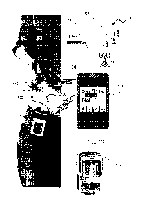
[0026] Figure 1 illustrates the system in which a controller for the pump or
glucose monitor(s)
is separate from both the infusion pump and the glucose monitor(s) and in
which a network can
be coupled to the controller to provide near real-time monitoring.
[0027] Figure 2A illustrates an exemplary embodiment of the diabetic
management system in
schematic form.
[0028] Figure 2B illustrates a plot of glucose value for a time interval of 48
hours (or in term
of k=12 for each hour of Caryl signal) in which other events such as missing
CGM data, sensor
replacement, or calibration measurements are superimposed on the glucose value
plot.
[0029] Figure 2C illustrates the tuning factor for a time interval of 48 hours
(or in term of k=12
time interval or index for each hour of CGM signal) in which the tuning factor
R is varied due
to missing CGM data, sensor replacement, and calibration measurement.
[0030] Figure 3 illustrates the logic utilized in the controller of Figure 1
or Figure 2A.
MODES FOR CARRYING OUT THE INVENTION
[0031] The following detailed description should be read with reference to the
drawings, in
which like elements in different drawings are identically numbered. The
drawings, which are
not necessarily to scale, depict selected embodiments and are not intended to
limit the scope of
the invention. The detailed description illustrates by way of example, not by
way of limitation,
the principles of the invention. This description will clearly enable one
skilled in the art to
make and use the invention, and describes several embodiments, adaptations,
variations,
alternatives and uses of the invention, including what is presently believed
to be the best mode
of carrying out the invention.
[0032] As used herein, the terms "about" or "approximately" for any numerical
values or
ranges indicate a suitable dimensional tolerance that allows the part or
collection of
components to function for its intended purpose as described herein. In
addition, as used
herein, the terms "patient," "host," "user," and "subject" refer to any human.
or animal subject
7
CA 02926047 2016-03-31
WO 2015/050699
PCT1US2014/056000
and are not intended to limit the systems or methods to human use, although
use of the subject
invention in a human patient represents a preferred embodiment. Furthermore,
the term "user"
includes not only the patient using a drug infusion device but also the
caretakers (e.g., parent or
guardian, nursing staff or home care employee). The term "drug" may include
hormone,
biologically active materials, pharmaceuticals or other chemicals that cause a
biological
response (e.g., glycemic response) in the body of a user or patient.
[0033] Figure 1 illustrates a drug delivery system 100 according to an
exemplary embodiment
that utilizes the principles of the invention. Drug delivery system 100
includes a drug delivery
device 102 and a remote controller 104. Drug delivery device 102 is connected
to an infusion
set 106 via flexible tubing 108.
[0034] Drug delivery device 102 is configured to transmit and receive data to
and from remote
controller 104 by, for example, radio frequency communication 112. Drug
delivery device 102
may also function as a stand-alone device with its own built in
microcontroller. In one
embodiment, drug delivery device 102 is an insulin infusion device and remote
controller 104
is a hand-held portable controller. In such an embodiment, data transmitted
from drug delivery
device 102 to remote controller 104 may include information such as, for
example, insulin
delivery data, blood glucose information, basal, bolus, insulin to
carbohydrates ratio or insulin
sensitivity factor, to name a few. The microcontroller 104 is configured to
include an MPC
controller 10 that has been programmed to receive continuous glucose readings
from a CUM.
sensor 112. Data transmitted from remote microcontroller 104 to insulin
delivery device 102
may include glucose test results and a food database to allow the drug
delivery device 102 to
calculate the amount of insulin to be delivered by drug delivery device 102.
Alternatively, the
remote microcontroller 104 may perform basal dosing or bolus calculation and
send the results
of such calculations to the drug delivery device. In an alternative
embodiment, an episodic
blood glucose meter 114 may be used alone or in conjunction with the CGM
sensor 112 to
provide data to either or both of the microcontroller 104 and drug delivery
device 102.
Alternatively, the remote microcontroller 104 may be combined with the meter
114 into either
(a) an integrated monolithic device; or (b) two separable devices that are
dockable with each
other to form an integrated device. Each of the devices 102, 104, and 114 has
a suitable micro-
controller (not shown for brevity) programmed to carry out various
functionalities.
8
CA 02926047 2016-03-31
WO 2015/050699
PCT1US2014/056000
[0035] Drug delivery device 102 may also be configured for bi-directional
wireless
communication with a remote health monitoring station 116 through, for
example, a wireless
communication network 118. Remote controller 104 and remote monitoring station
116 may
be configured for hi-directional wired communication through, for example, a
telephone land
based communication network. Remote monitoring station 116 may be used, for
example, to
download upgraded software to drug delivery device 102 and to process
information from drug
delivery device 102. Examples of remote monitoring station 116 may include,
but are not
Limited to, a personal or networked computer 126, server 128 to a memory
storage, a personal
digital assistant, other mobile telephone, a hospital base monitoring station
or a dedicated
remote clinical monitoring station.
[0036] Drug delivery device 102 includes electronic signal processing
components including a
central processing unit and memory elements for storing control programs and
operation data,
a radio frequency module 116 for sending and receiving communication signals
(i.e.,
messages) to/from remote controller 104, a display for providing operational
information to the
user, a plurality of navigational buttons for the user to input information, a
battery for
providing power to the system, an. alarm. (e.g., visual, auditory or tactile)
for providing
feedback to the user, a vibrator for providing feedback to the user, a drug
delivery mechanism
(e.g. a drug pump and drive mechanism) for forcing a insulin from a insulin
reservoir (e.g., a
insulin cartridge) through a side port connected to an infusion set 108/106
and into the body of
the user. An example of a drug delivery device 102 (or pump 16) can be in the
form of a
modified Animas Vibe insulin pump manufactured by Animas Corporation in Wayne,
Pennsylvania USA.
[0037] Glucose levels or concentrations can be determined by the use of the
CGM sensor 112.
The CGM sensor 112 utilizes amperometric electrochemical sensor technology to
measure
glucose with three electrodes operably connected to the sensor electronics and
are covered by a
sensing membrane and a biointerface membrane, which are attached by a clip.
[0038] The top ends of the electrodes are in contact with an electrolyte phase
(not shown),
which is a free-flowing fluid phase disposed between the sewing membrane and
the
electrodes. The sensing membrane may include an enzyme, e.g., glucose oxidase,
which
9
covers the electrolyte phase. In this exemplary sensor, the counter electrode
is provided to
balance the current generated by the species being measured at the working
electrode. In the
case of a glucose oxidase based glucose sensor, the species being measured at
the working
electrode is H202. The current that is produced at the working electrode (and
flows through
the circuitry to the counter electrode) is proportional to the diffusional
flux of H202 generated
by this electrochemical transformation of glucose into its enzymatic
byproducts. Accordingly,
a raw signal may be produced that is representative of the concentration of
glucose in the
user's body, and therefore may be utilized to estimate a meaningful glucose
value. Details of
the sensor and associated components are shown and described in US Patent No.
7,276,029. In
one embodiment, a continuous glucose sensor from the Dexcom Seven System
(manufactured by Dexcom Inc.) can also be utilized with the exemplary
embodiments
described herein.
[0039] In one embodiment of the invention, the following components can also
be utilized as a
system for management of diabetes that is akin to an artificial pancreas:
OneTouch Ping
Glucose Management System by Animas Corporation that includes at least an
infusion pump
and an episodic glucose sensor; and DexCom0 G4 Platinum CGM by DexCom
Corporation
with interface to connect these components and programmed in MATLABOlanguage
and
accessory hardware to connect the components together; and control algorithms
in the form of
an MPC that automatically regulates the rate of insulin delivery based on the
glucose level of
the patient, historical glucose measurement and anticipated future glucose
trends, and patient
specific information.
[0040] Figure 2A illustrates a schematic diagram 200 of the system 100 in
Figure 1
programmed with the solution devised by applicants to counteract a less than
desirable effect
of a closed-loop control system. In particular, Figure 2A provides for an MPC
programmed
into a control logic module 10 that is utilized in controller 104. MPC logic
module 10 receives
a desired glucose concentration or range of glucose concentration 12 (along
with any
modification from an update filter 28 so that it is able to maintain the
output (i.e., glucose
level) of the subject within the desired range of glucose levels.
Date Recue/Date Received 2020-12-30
CA 02926047 2016-03-31
WO 2015/050699
PCT1US2014/056000
[0041] Referring to Figure 2A, the first output 14 of the MPC-enabled control
logic 10 can be
a control signal to an insulin pump 16 to deliver a desired quantity of
insulin 18 into a subject
20 at predetermined time intervals, which can be indexed every 5 minutes using
time interval
index k. A second output in the form of a predicted glucose value 15 can be
utilized in control
junction B. A glucose sensor 22 (or 112 in Fig. 1) measures the glucose levels
in the subject
20 in order to provide signals 24 representative of the actual or measured
glucose levels to
control junction B, which takes the difference between measured glucose
concentration 24 and
the MPC predictions of that measured glucose concentration. This difference
provides input
for the update filter 26 of state variables of the model. The difference 26 is
provided to an
estimator (also known as an update filter 28) that provides for estimate of
state variables of the
model that cannot be measured directly. The update filter 28 is preferably a
recursive filter in
the form of a Kalman filter with tuning parameters for the model. The output
of the update or
recursive filter 28 is provided to control junction A whose output is utilized
by the MPC in the
control logic 10 to further refine the control signal 14 to the pump 16 (or
102 in Fig. 1). A
tuning factor 34 is used with the MPC controller 10 to "tune" the controller
in its delivery of
the insulin. To accomplish this, applicants have devised the use of a
calibration index module
30 and data omission module 32 to adjust the tuning factor. Calibration index
module 30 is
configured to track the number of glucose measurement calibration, which is
typically
accomplished by an episodic glucose monitor, such as, for example, a blood
glucose test strip
and meter system. Data omission index module 32 is configured to track the
number of
missing measurements or data from the continuous glucose monitor 22.
[0042] A brief overview of the MPC noted above that is used in control logic
10 is warranted
here. The MPC logic is formulated to control a subject glucose level to a safe
glucose zone,
with the lower blood glucose limit of the zone varying between 80-100 mg/d1L
and the upper
blood glucose limit varying between about 140-180 mg/d1..; the algorithm will
henceforth be
referred to as the "zone MPC'". Controlling to a target zone is, in general,
applied to controlled
systems that lack a specific set point with the controller's goal being to
keep the controlled
variable, (CV), for example the glucose values, in a predefined zone. Control
to zone (i.e., a
nonnaglycemic zone) is highly suitable for the artificial pancreas because of
the absence of a
natural glycemic set point. Moreover, an inherent benefit of control to zone
is the ability to
11
CA 02926047 2016-03-31
WO 2015/050699
PCT1US2014/056000
limit pump actuation/activity in a way that if glucose levels are within the
zone then no extra
correction shall be suggested.
[0043] in real-time, the insulin delivery rate ID from the zone MPC law is
calculated by an on-
line optimization, which evaluates at each sampling time the next insulin
delivery rate. The
optimization at each sampling time is based on the estimated metabolic state
(plasma glucose,
subcutaneous insulin) obtained from the dynamic model stored in module 10.
[0044] The MPC of control logic 10 incorporates an explicit model of human
11DM glucose-
insulin dynamics. The model is used to predict future glucose values and to
calculate future
controller moves that will bring the glucose profile to the desired range. MPC
in controllers
can be formulated for both discrete- and continuous-time systems; the
controller is set in
discrete time, with the discrete time (stage) index k referring to the epoch
of the kth sample
occurring at continuous time t = k = Tõ where T, =5 min is the sampling
period. Software
constraints ensure that insulin delivery rates are constrained between minimum
(i.e., zero) and
maximum values. The first insulin infusion (out of N steps) is then
implemented. At the next
time step, k +1 based on the new measured glucose value and the last insulin
rate, the process
is repeated.
[0045] Specifically, we start with the original linear difference model used
for zone MPC:
G 1(0= aiG(k -1) + a2G. (k -2) + a3G(k- -3) + a4G'(k - 4)+ a5G(k - 5) + b m (k
- 4)
I m (k). ciI m (k -1) + I m (k - 2) +d11'/) (k - 1) + D (k -2) al- (1)
where:
is the discrete time interval index having a series of indexing counters where
k=1, 2, 3 ...
G' is the measured glucose concentration
im is the "mapped insulin" which is not a measured quantity
I'D is the delivered insulin or a manipulated variable
12
CA 02926047 2016-03-31
WO 2015/050699 PCT1US2014/056000
and coefficients ai 2.993; a2-(-3.775); a3-2.568; a4-(-0.886); a5-0.09776;
1)+13);
er-1.665; er-(-0.693); dr-0.01476; d2-0.01306.
[0046] Using the FDA accepted metabolic simulator known to those skilled in
the art, Eq. (1)
can be reduced to the following linear difference model in Equation (2):
(a) GI (k)= 2.9936÷(k ¨1) ¨3.775G1(k ¨2) + 2.568C(k ¨3) ¨ 0.886G1(k ¨4)
+ 0.09776G'(k ¨5)
¨1.5I m(k ¨ 4)
+ 0.1401Mealm(k ¨2) +1.933Meal m (k ¨ 3)
(2)
(b) I m (k) = 1.665/m (k ¨1)-0.6931 m (k ¨2)
+ 0.014764'(k ¨1) + 0.0130610' (k ¨2)
(c) Meal m (k) = 1.501Meal m (k ¨1) + 0.5427 Meal m (k 2)
+ 0.02279Meal(k ¨1) + 0.01859Meal(k 2)
where:
G' is the glucose concentration output (G) deviation variable
(mg/d1.,), i.e.
G ¨110 mg/d1..,
ID' is the insulin infusion rate input (ID) deviation variable (U/h),
i.e.
¨ basal U/h,
Meal is the CHO ingestion input (gram- CHO),
/M is the mapped subcutaneous insulin infusion rates (U/h), and
Mea/m is the mapped CHO ingestion input (gram- CHO).
[0047] The dynamic model in Eq. (2) relates the effects of insulin infusion
rate (/D), and CHO
ingestion input (Meal) on plasma glucose. The model represents a single
average model for
the total population of subjects. The model and its parameters are fixed.
[0048] The second-order input transfer functions described by parts (b) and
(c) in Eq. (2) are
used to generate an artificial input memory in the zone MPC schema to prevent
insulin over-
dosing, and consequently prevent hypoglycemia. In order to avoid over-delivery
of insulin, the
13
evaluation of any sequential insulin delivery must take into consideration the
past administered
insulin against the length of the insulin action. However, a one-state linear
difference model
with a relatively low order uses the output (glycemia) as the main source of
past administered
input (insulin) "memory." In the face of the model mismatch, noise, or change
in the subject's
insulin sensitivity, this may result in under- or over-delivery of insulin.
This is mitigated by
adding two additional states (IM and Mea/m) for the mapped insulin and meal
inputs that carry a
longer insulin memory.
[0049] Zone MPC is applied when the specific set point value of a controlled
variable (CV) is
of low relevance compared to a zone that is defined by upper and lower
boundaries.
Moreover, in the presence of noise and model mismatch there is no practical
value using a
fixed set point. Zone MPC was developed through research by the University of
California at
Santa Barbara and the Sansum Diabetes Research Institute. Other details of the
derivation for
the Zone MPC technique are shown and described in Benyamin Grosman, Ph.D.,
Eyal Dassau,
Ph.D., Howard C. Zisser, M.D., Lois Jovanovie, M.D., and Francis J. Doyle III,
Ph.D. "Zone
Model Predictive Control: A Strategy to Minimize Hyper and Hypoglycemic
Events" Journal of
Diabetes Science and Technology, Vol. 4, Issue 4, July 2010, and US Patent
Application
Publication No. 2011/0208156 to Doyle et al., entitled "Systems, Devices, and
Methods to
Deliver Biological Factors or Drugs to a Subject," with the publication date
of August 25,
2011. Additional details of the Zone MPC are shown and described in US Patent
Application
Publication No. 20110208156. A related derivation of zone MPC was presented in
Maciejowski JM., "PREDICTIVE CONTROL WITH CONSTRAINTS- Harlow, UK: Prentice-
Hall,
Pearson Education Limited, 2002. The zone MPC is implemented by defining fixed
upper and
lower bounds as soft constraints by letting the optimization weights switch
between zero and
some final values when the predicted CVs are in or out of the desired zone,
respectively. The
predicted residuals are generally defined as the difference between the CV
that is out of the
desired zone and the nearest bound. Zone MPC is typically divided into three
different zones.
The permitted range is the control target and it is defined by upper and lower
bounds. The
upper zone represents undesirable high predicted glycemic values. The lower
zone represents
14
Date Recue/Date Received 2020-12-30
CA 02926047 2016-03-31
WO 2015/050699
PCT1US2014/056000
undesirable low predicted glycemic values that represent hypoglycemic zone or
a pre-
hypoglycemic protective area that is a low alarm zone. The zone MPC optimizes
the predicted
glycemia by manipulating the near-future insulin control moves to stay in the
permitted zone
under specified constrains.
[0050] The core of zone MPC lies in its cost function formulation that holds
the zone
formulation. Zone .M.PC, like any other forms of MPC, predicts the future
output by an explicit
model using past input/output records and future input moves that need to be
optimized.
However, instead of driving to a specific fixed set point, the optimization
attempts to keep or
move the predicted outputs into a zone that is defined by upper and lower
bounds. Using a
linear difference model, the glycemic dynamics are predicted and the
optimization reduces
future glycemic excursions from the zone under constraints and weights defined
in its cost
function.
[0051] The zone MPC cost function .1 used in the presented work is defined as
follows:
Dt = Q EIGe (k AI+ R +j)II
s.t. (3)
G(k + j) = f[G(k + j õ;(k. + j ¨1)] Vs/ =1,P
¨ basal(k +/) 1. De (k + 72 'If = 0,M ¨1
or for our applications:
.1(1 Di) = EIG""(k + Ai+ R = Epp (k + j) basal(k + (4)
where
.1 is a cost function;
Q is a weighting factor on the predicted glucose term;
R is a tuning factor on the future proposed inputs in the cost function;
f is the prediction function (in Eq. (2)); and
vector /D contains the set of proposed near-future insulin infusion amounts.
It is the
"manipulated variable" because it is manipulated in order to find the minimum
in .1.
CA 02926047 2016-03-31
WO 2015/050699 PCT1US2014/056000
Cra"e is a variable quantifying the deviation of future model-predicted CCiM
values G outside a
specified glycemic zone, and is determined by making the following
comparisons:
0 if G < G < G
CP' =µG ¨Gzu if' G > G zH (5)
tGzz ¨G if G <
where the glycemic zone is defined by the upper limit Gza and the lower limit
Ga.
[0052] Thus, if all the predicted glucose values are within the zone, then
every element of Cr'
is equal to 0, and consequently I is minimized with ID = basal for that time
of day, i.e., the
algorithm "defaults" to the patient's current basal insulin infusion rate. On
the other hand, if
any of the predicted glucose values are outside the zone, then G > 0 and thus
"contribute" to
the cost function. In this case, the near-future proposed insulin infusion
amounts ID will
deviate from the basal in order to prevent out-of-zone deviation in G.'"e from
ever happening,
which will also "contribute" to the cost function. Then, a quantitative
balance is found in the
optimization, based on the weighting factor R.
[0053] In order to solve optimization problem of Equations (2)-(5),
commercially available
software (e.g., MATI,AB's "fmincon.m" function) is utilized. For this
function, the following
parameters are used for each optimization:
o Initial guess for the insulin delivery rates, ii) '(0), is the null
vector 0 G Rm , e.g.,
if M = 5 the initial guess for each optimization is ID' = [0 0 0 0 0]. This
implies that the
initial guess is equivalent to the basal rate.
o Maximum number of function evaluations allowed is Max_f= 100*1W', where M
is control horizon as described earlier.
o Maximum number of iterations is Maxi = 400, which is fixed.
o Termination on the cost function values Term cost = le-6, which is fixed.
o Termination tolerance Term to! on the manipulated variables ID' is le-6.
[0054] The following hard constraints are implemented on the manipulated
variables (ID'):
¨ basal I D'n; 72 UM (6)
16
where basal is the subject's basal rate as set by the subject or his/her
physician,
expected in the range of about 0.6 to about 1.8 U/hr.
[0055] Although the values of control horizontal parameter M and prediction
horizon
parameter P have significant effects on the controller performance, and are
normally used to
tune an MPC based controller, they can be heuristically tuned based on
knowledge of the
system. Tuning rules are known to those skilled in the field. According to
these rules, M and
P may vary between:
2 < M <10
(7)
20 < P <120
[0056] In the preferred embodiments, we use the nominal values of M= 5 and P =
108.
[0057] The ratio of the output error weighting factor Q and the input change
weighting matrix
or tuning factor R may vary between:
-1i1000 (8)
[0058] In the preferred embodiments, we may use the nominal value of RIQ =
500.
[0059] Once the controller 10 is initialized and switched on in the
microcontroller in device
102 or 104, real-time calculations take place every five minutes,
corresponding to the sample
time for the glucose sensor 22. The first element of ID is delivered as an
insulin dose to the
patient through the insulin pump 16, five minutes elapse, a new CGM reading
becomes
available, and the process repeats. It is noted that the future control moves
are hard-
constrained, set by the insulin pump's ability to deliver a maximum rate of
insulin and the
inability to deliver negative insulin values. Other details of related subject
matter including
state estimator, and other MPC are provided by Rachel Gillis et al., "Glucose
Estimation and
Prediction through Meal Responses Using Ambulatory Subject Data for Advisory
Mode Model
Predictive Control" Journal of Diabetes Science and Technology Vol. 1, Issue
6, Nov. 2007
and by Youqing Wang et al., "Closed-Loop Control of Artificial Pancreatic
fl¨Cell in Type I
Diabetes Mellitus Using Model Predictive Iterative Learning Control" IEEE
Transactions on
Biomedical Engineering, Vol. 57, No. 2, February 2010.
17
Date Recue/Date Received 2020-12-30
CA 02926047 2016-03-31
WO 2015/050699
PCT1US2014/056000
[0060] It is known that the tuning parameter or tuning factor (designated here
as "R") can
have a significant effect on the quality of the glucose control. The parameter
known as the
aggressiveness factor, gain, among other names ¨ determines the speed of
response of the
algorithm to changes in glucose concentration. A relatively conservative value
of R results in
a controller that is slow to adjust insulin infusion amounts (relative to
basal) in response to
changes in glucose; on the other hand, a relatively aggressive value of R
results in a controller
that is quick to respond to changes in glucose. In principle, an aggressive
controller would
result in the best glucose control if 1) the available glucose measurements
are accurate, and
moreover 2) the model predictions of future glucose trends are accurate. If
these conditions
are not true, then it may be safer to use a conservative controller.
[0061] A discussion of the tuning factor R (referenced here as 34) in Fig. 2A
is worthwhile at
this point. As it is not straightforward to determine either the accuracy of
the glucose
measurements on-line or the accuracy of the model predictions, it can be
difficult to know the
appropriate tuning factor 34 or R to use for the current conditions. However,
in specific
circumstances, it is possible to ascertain with a high degree of certainty
when a continuous
glucose monitor (CGM) has become "less accurate" or "more accurate" in a
qualitative sense.
[0062] Applicants believe that it is reasonable to assume that a CGM may
become less
accurate with each sample following a calibration, and has suddenly become
less accurate
when it fails to report a glucose measurement. Missed or omitted COM
measurements may be
due to uncertainty in the glucose trend (a CGM algorithm feature) or simply to
radio frequency
communication issues. Similarly, it is reasonable to assume that the COM has
become more
accurate following a calibration, and following a reestablishment of reporting
glucose values
after one or more missed readings.
[0063] Applicants have discovered therefore that it is possible to use these
insights to tune the
controller automatically, i.e., use a more conservative value of R for the
tuning factor when the
COM has become less accurate, and a more aggressive value when the COM has
become more
accurate. This is demonstrated, in a general sense, below.
[0064] Let the aggressiveness or tuning factor, R, be bounded by the constants
Rmin (for the
most aggressive controller) and Rmax (for the most conservative controller):
18
CA 02926047 2016-03-31
WO 2015/050699
PCT1US2014/056000
Rmin R ez= Rmax Eq. (9)
[0065] Let there be two nominal increments, strictly positive quantities: ri.
a relatively small
increment associated with the accuracy of a CGM in relation to how recent a
calibration was,
and r2, a larger increment associated with the accuracy of a CGM: as it
pertains to missed
samples.
[0066] The tuning factor to be used in the MPC calculation for the current
sampling instant,
indexed by k, is R(k), where R(k) is automatically updated at each sample
based on a nominal
R value, RNOM, which could in general be different for each user:
R(k) = R
-NOM reCAL(k) + r2*MISSED(k), Eq. (10)
and RmEN R(k) RmAx al- (11)
CAL(k) = k Icem, - 6 for k k(;AL >= 6 Eq.(12)
CAL(k) = k 4,41.2 -- 6 for k .11, <6 Eq.(13)
where: RMAX < 100* RNOM
RNom/100 < RMEN < RNOM
(RmAX RMIN)/500 <11 < (..RmAx - RmiN)/50
(RmAx RNITN)/50 < r2 < (RmAx RmIN)/5
CAL(k) is the calibration index.
[0067] It is noted that RNOM can be a value from about zero to about 1000
(e.g.,
O<RNom<I000; although it should be noted that this value and range are
dependent on the
specific cost function in the particular model being used and one skilled in
the art would be
able to configure the appropriate range for RNOM, depending on the model being
used. In the
19
exemplary embodiments. ri can be any number from about 1 to about 50 and r2
can be any
number from about 10 to about 1000 and preferably about 500. Although the
tuning factor has
been provided as a range of specific numerical values for the embodiments
described herein,
we note that each system would use different configurations of the tuning
factor to control the
desired response of the controller (and pump) in delivering the insulin.
Hence, it is our intent
not to be bound to any specific numerical value and therefore, as described
herein, the tuning
factor may include any value from a first value or interval that will cause
the pump to have a
very quick (or highly aggressive) response in delivering the insulin to a
second value or
interval that will cause the pump to have very slow (or conservative) response
in delivering
insulin.
[0068] The current sample index is "k" where kcAL is the sample index of the
most recent
CGM calibration with a suitable referential glucose analyzer or glucose meter
114, and kcAL2 is
the sample index of the second-most recent CGM calibration with a referential
glucose meter
114. Thus, 30 min (e.g., 6 samples) following a calibration with the
referential glucose meter
114, calibration index module 32 or CAL(k) is zero. Thereafter, CAL grows by
one at each
sample until the 30 min after the next calibration. This correction to the
tuning factor R of
module 34 at instance "k" (i.e., R(k)) results in a slightly more conservative
controller (i.e.,
higher value of R for Equation (4)) with every consecutive CGM measurement by
sensor 112
for each time interval index k, until the next calibration. The 30 minute
buffer immediately
following a calibration, during which the control logic 10 will act relatively
conservatively, is
due to potentially significant "jumps" in CGM values immediately following
calibrations.
[0069] Additional details of how the tuning factor R is adjusted for certain
events (e.g., signal
dropouts or calibration) can be seen in US Patent Application S.N. 13/708,032
filed on
December 7, 2012.
[0070] Besides the adjustment of the tuning factor for CGM signal drops or
calibrations, we
have also devised a strategy to deal with the inaccuracy of CGM sensor
whenever such sensor
is initially installed (or replaced with another one) on the skin of the user.
Date Recue/Date Received 2020-12-30
CA 02926047 2016-03-31
WO 2015/050699
PCT1US2014/056000
[0071] To recap, the system of Figure 2A is provided to manage diabetes of a
subject. In this
system, the following components are utilized: an episodic glucose meter 29,
continuous
glucose sensor 22, pump 16, and controller 10. The meter 29 measures blood
glucose of a
subject at discrete non-uniform time intervals (e.g., every 4 hours) and
provide such episodic
blood glucose level as a calibration index 30 for each interval in a time
interval index (k where
a time interval between k and k-F1 is about 5 minutes). The continuous glucose
monitor
continuously measure glucose level of the subject at discrete generally
uniform time intervals
(e.g., approximately every 30 seconds or every minute) and provide the glucose
level at each
interval in the form of glucose measurement data, in which any omission of a
glucose
measurement in any interval is stored in an omission index 32. The insulin
infusion pump is
controlled by the controller 10 to deliver insulin to the subject 20. As used
herein, the term
"insulin" is not limited to the peptide hormone extracted from animals or
genetically
engineered insulin, biosynthetic recombinant human insulin, or its analogues
but may include
other drugs or biologics designed to mimic insulin or other materials having
similar effects of
insulin on the human body. The controller 10 is programmed with the
appropriate MPC
program to control the pump and communicate with the glucose meter and the
glucose
monitor. In this aspect, the controller determines a tuning factor 34 based on
(a) a calibration
index 30 derived from episodic blood glucose measurements and (b) an omission
index 32 for
the MPC 10 such that controller determines an insulin delivery rate for each
time interval in
the time interval index (k) from the model predictive control based on ( I)
desired glucose
concentration 12, (2) glucose concentration 24 measured by the monitor 22 at
each interval of
the interval index (k), and (3) the tuning factor 34. However, we have devised
the system so
that when there is a change or replacement of the COM sensor (which sensor
replacement can
be detected by the pump or confirmed by the user via a switch), the system
sets the tuning
factor R to a conservative value such as, for example, 500, for a
predetermined time period
such as, for example, 8 hours, 12 hours, 24 hours or longer or shorter as
appropriate for the
inherent inaccuracy of the particular CGM sensor being used.
[0072] With reference to Figures 2B and 2C, telemetry outputs of the system
are provided to
demonstrate operation of this system. In Figure 2B, CGM output signal are
shown over 48
hours whereas an output of the tuning factor over the same time frame in
Figure 2C is
CA 02926047 2016-03-31
WO 2015/050699
PCT1US2014/056000
juxtaposed below Figure 2B. At event "a" in Figure 2B, a calibration is made
which means
that, in a qualitative sense, the output signal from the CGM sensor can be
viewed as being
more accurate (because of the calibration with the episodic glucose sensor or
test strip).
Hence, at "b" in Figure 2C, the MPC (in the microcontroller) can increase the
aggressiveness
of the tuning factor R (reducing its numerical value to 50) and slowly ramping
the
aggressiveness of the factor R higher in the next two hours (from 12hours to
14 hours). At
event "c" in Figure 2B, the microcontroller detects from a flag or switch 36
(or the user can
confirm) that the CGM sensor has been changed to a new CGM sensor. The
microcontroller,
as programmed with an embodiment of our invention, immediately switches the
tuning factor
to a more conservative tuning factor so that the dosing of insulin is more
conservative. And
for a predetermined time period, from. 14 hours to about 40 hours, this more
conservative
tuning factor is maintained for a predetermined time (e.g., from 14 hours to
about 40 hours)
regardless of dropped signals from the new CGM sensor. As used herein, the
phrase
"conservative tuning factor" indicates a tuning factor R for the controller
that is intended to
ensure that the insulin dosing delivery rate (relative to basal in response to
changes in glucose
for the intended application) that is slow enough and within the constraints
in the particular
application of the system to meet the safety or regulatory requirements for
such application.
As a non-limiting example, the conservative tuning factor can be any value
from about 500 to
1000. But it should be clear that this tuning factor can be any number that is
used to affect the
response or "gain" of the particular configuration of a system utilizing a
closed-loop controller
(feedback, feedforward or hybrid controller) as long as such tuning factor is
considered to be
safe or conservative by those skilled in the art.
[0073] By virtue of the disclosure provided herein, applicants have also
devised a method to
control an infusion pump to control an infusion pump with a controller to
control the pump and
receive data from at least one glucose sensor. With reference to Figure 3,
exemplary method
will now be described. The method starts by measuring in step 302 a glucose
level in the
subject from the glucose sensor (22 or 29) to provide at least one glucose
measurement for
each time interval in a series of discrete time interval index ("k"). At step
304, the system
queries as to whether a CGM sensor change has been made within a predetermined
time period
X. A determination of a sensor change in 304 can be obtained by the
microcontroller checking
22
CA 02926047 2016-03-31
WO 2015/050699
PCT1US2014/056000
a sensor change log, sensor change flag, or by a combinations of one or more
signals indicative
of a sensor change (e.g., a user manually actuated signal). If this query
returns a "true" or a
"yes", the system checks at step 306 if a countdown timer for predetermined
time X is equal to
zero (or a count-up timer being equal to the predetermined time X). If not
true (i.e., a "no"),
the system moves to step 308 where the tuning factor is set to a conservative
value. At step
312, the MPC in the microcontroller now determines the appropriate insulin
dosing ID (from
Equations 2-5) within the zone taking into account the cost j, which is
affected by the tuning
factor R. At step 314, the microcontroller actuates the pump motor in the pump
102 to deliver
the appropriate insulin dose calculated in step 312. At step 316, the
microcontroller returns to
the main routine.
[0074] On the other hand, if the query at step 304 returns a false (i.e., a
"no"), the system
maintains the tuning factor as currently set prior to the sensor change event.
Alternatively, the
system can still calculate the appropriate tuning factor for the work load as
described earlier in
relation to Equations 9-13.
[0075] While the invention has been described in terms of particular
variations and illustrative
figures, those of ordinary skill in the art will recognize that the invention
is not limited to the
variations or figures described. For example, the closed-loop controller need
not be an MPC
controller but can be, with appropriate modifications by those skilled in the
art, a ND
controller, a PID controller with internal model control (IMC), a model-
algorithmic-control
(MAC) that are discussed by Percival et al., in "Closed-Loop Control and
Advisory Mode
Evaluation of an Artfficial Pancreatic fi Cell: Use of Proportional-Integral-
Derivative
Equivalent Model-Based Controllers" Journal of Diabetes Science and
Technology, Vol. 2,
Issue 4, July 2008. In addition, where methods and steps described above
indicate certain
events occurring in certain order, those of ordinary skill in the art will
recognize that the
ordering of certain steps may be modified and that such modifications are in
accordance with
the variations of the invention. Additionally, certain of the steps may be
performed
concurrently in a parallel process when possible, as well as performed
sequentially as
described above. Therefore, to the extent there are variations of the
invention, which are
within the spirit of the disclosure or equivalent to the inventions found in
the claims, it is the
intent that this patent will cover those variations as well.