Note: Descriptions are shown in the official language in which they were submitted.
CA 2926243 2017-04-21
81795921
DECORRELATOR STRUCTURE
FOR PARAMETRIC RECONSTRUCTION OF AUDIO SIGNALS
Cross-Reference to Related Applications
This application claims priority from U.S. Provisional Patent Applications
Nos.
61/973,646 filed 1 April 2014 and 61/893,770 filed 21 October 2013.
Technical field
The invention disclosed herein generally relates to encoding and decoding of
audio signals, and in particular to parametric reconstruction of a plurality
of audio
signals from a downmix signal and associated metadata.
Background
Audio playback systems comprising multiple loudspeakers are frequently used
to reproduce an audio scene represented by a plurality of audio signals,
wherein the
respective audio signals are played back on respective loudspeakers. The audio
signals may for example have been recorded via, a plurality of acoustic
transducers or
may have been generated by audio authoring equipment. In many situations,
there
are bandwidth limitations for transmitting the audio signals to the playback
equipment
and/or limited space for storing the audio signals in a computer memory or on
a
portable storage device. There exist audio coding systems for parametric
coding of
audio signals, so as to reduce the bandwidth or storage size needed. On an
encoder
side, these systems typically downmix the audio signals into a downmix signal,
which
typically is a mono (one channel) or a stereo (two channels) downmix, and.
extract
side information describing the properties of the audio signals by means of
parameters like level differences and cross-correlation. The downmix and the
side
information are then encoded and sent to a decoder side. At the decoder side,
the
plurality of audio signals is reconstructed, i.e. approximated, from the
downmix under
control of the parameters of the side inforrnation. Decorrelators are often
employed
as part of parametric reconstruction for increasing the dimensionality of the
audio
content provided by the downmix, so as to allow a more faithful reconstruction
of the
plurality of audio signals. How to design and implement decorrelators may be
key
factors for increasing the fidelity of the reconstruction.
- 1 -
CA 02926243 2016-04-04
WO 2015/059152 PCT/EP2014/072568
In view of the wide range of different types of devices and systems available
for playback of a plurality of audio signals representing an audio scene,
including an
emerging segment aimed at end-users in their homes, there is a need for new
and
alternative ways to efficiently encode a plurality of audio signals, so as to
reduce
bandwidth requirements and/or the required memory size for storage, and/or to
facilitate reconstruction of the plurality of audio signals at a decoder side.
Brief description of the drawings
In what follows, example embodiments will be described in greater detail and
with reference to the accompanying drawings, on which:
Fig. 1 is a generalized block diagram of a parametric reconstruction section
for
reconstructing a plurality of audio signals based on a downmix signal and
associated
wet and dry upmix coefficients, according to an example embodiment;
Fig. 2 is a generalized block diagram of an audio decoding system comprising
the parametric reconstruction section depicted in Fig. 1, according to an
example
embodiment;
Fig. 3 is a generalized block diagram of a parametric encoding section for
encoding a plurality of audio signals as a data suitable for parametric
reconstruction,
according to an example embodiment; and
Fig. 4 is a generalized block diagram of an audio encoding system comprising
the parametric encoding section depicted in Fig, 3, according to an example
embodiment.
All the figures are schematic and generally only show parts which are
necessary in order to elucidate the invention, whereas other parts may be
omitted or
merely suggested.
Description of example embodiments
As used herein, an audio signal may be a pure audio signal, an audio part of
an audiovisual signal or multimedia signal or any of these in combination with
metadata.
As used herein, a channel is an audio signal associated with a
predefined/fixed spatial position/orientation or an undefined spatial position
such as
"left" or "right".
- 2 -
CA 2926243 2017-04-21
81795921
=
As used herein, an audio object or audio object signal is an audio signal
associated with a spatial position susceptible of being time-variable, i.e. a
spatial
position whose value may be re-assigned or updated over time.
I. Overview
According to a first aspect, example embodiments propose audio decoding
systems as well as methods and computer program products for reconstructing a
plurality of audio signals. The proposed decoding systems, methods and
computer
program products, according to the first aspect, may generally share the same
features and advantages.
According to example embodiments, there is provided a method for
reconstructing a plurality of audio signals. The method comprises: receiving a
time/frequency tile of a downmix signal together with associated wet and dry
upmix
coefficients, wherein the downmix signal comprises fewer channels than the
number
of audio signals to be reconstructed; computing a first signal with one or
more
channels, referred to as an intermediate signal, as a linear mapping of the
downmix
signal, wherein a first set of coefficients is.applied to the channels of the
downmix
signal as part of computing the intermediate signal; generating a second
signal with
one or more channels, referred to as a decorrelated signal, by processing one
or
more channels of the intermediate signal; computing a third signal with a
plurality of
channels, referred to as a wet upmix signal, as a linear mapping of the
decorrelated
signal, wherein a second set of coefficients is applied to one or more
channels of the
decorrelated signal as part of computing the wet upmix signal; computing a
fourth
signal with a plurality of channels, referred to as a dry upmix signal, as a
linear
mapping of the downmix signal, wherein a third set of coefficients is applied
to the
channels of the downmix signal as part of computing the dry upmix signal; and
combining the wet and dry upmix signals to obtain a multidimensional
reconstructed
signal corresponding to a time/frequency tile of the plurality of audio
signals to be
reconstructed. In the present example embodiment, the second and third sets of
coefficients correspond to the received wet and dry upmix coefficients,
respectively;
and the first set of coefficients is computed, according to a predefined rule,
based on
the wet and dry upmix coefficients.
- 3 -
CA 2926243 2017-04-21
81795921
According to one aspect of the present invention, there is provided a
method for reconstructing a plurality of audio signals (X), comprising:
receiving a
time/frequency tile of a downmix signal (Y) together with associated wet and
dry
upmix coefficients, wherein the downmix signal comprises fewer channels than
the
number of audio signals to be reconstructed; computing an intermediate signal
(W)
as a linear mapping of the downmix signal, wherein a first set of coefficients
(Q) is
applied to the channels of the downmix signal; generating a decorrelated
signal (2)
by processing one or more channels of the intermediate signal; computing a wet
upmix signal as a linear mapping of the decorrelated signal, wherein a second
set of
coefficients (P) is applied to one or more channels of the decorrelated
intermediate
signal; computing a dry upmix signal as a linear mapping of the downmix
signal,
wherein a third set of coefficients (c) is applied to the channels of the
downmix
signal; and combining the wet and dry upmix signals to obtain a
multidimensional
reconstructed signal (9) corresponding to a time/frequency tile of said
plurality of
audio signals to be reconstructed, wherein said second and third sets of
coefficients
coincide with, or are derived from, the received wet and dry upmix
coefficients,
respectively, wherein the method comprises computing said first set of
coefficients
based on the received wet and dry upmix coefficients such that the
intermediate
signal, which is to be processed into the decorrelated signal, is obtained by
a linear
mapping of the dry upmix signal.
According to another aspect of the present invention, there is provided
an audio decoding system with a parametric reconstruction section adapted to
receive a time/frequency tile of a downmix signal (Y) and associated wet and
dry
upmix coefficients (P, C), and to reconstruct a plurality of audio signals
(X:), wherein
the downmix signal has fewer channels than the number of audio signals to be
reconstructed, the parametric reconstruction section comprising: a pre-
multiplier
configured to receive the time/frequency tile of the downmix signal and to
output an
intermediate signal (W) computed by mapping the downmix signal linearly in
accordance with a first set of coefficients (Q); a decorrelating section
configured to
receive the intermediate signal and to output, based thereon, a decorrelated
signal
- 3a -
CA 2926243 2017-04-21
81795921
(7); a wet upmix section configured to receive the wet upmix coefficients (P)
as well
as the decorrelated signal, and to compute a wet upmix signal by mapping the
decorrelated signal linearly in accordance with the wet upmix coefficients; a
dry
upmix section configured to receive the dry upmix coefficients (C) and, in
parallel to
the pre-multiplier, the time/frequency tile of the downmix signal, and to
output a dry
upmix signal computed by mapping the downmix signal linearly in accordance
with
the dry upmix coefficients; and a combining section configured to receive the
wet
upmix signal and the dry upmix signal and to combine these signals to obtain a
multidimensional reconstructed signal ();?) corresponding to a time/frequency
tile of
said plurality of audio signals to be reconstructed, wherein the parametric
reconstruction section further comprises a converter configured to receive the
wet
and dry upmix coefficients, to compute, according to a predefined rule, the
first set of
coefficients and to supply this to the pre-multiplier, and wherein the pre-
multiplier is
further configured to obtain the intermediate signal by a linear mapping of
the dry
upmix signal.
According to still another aspect of the present invention, there is
provided a method for encoding a plurality of audio signals (X) as data
suitable for
parametric reconstruction, comprising: receiving a time/frequency tile of said
plurality
of audio signals; computing a downmix signal (Y) by forming linear
combinations of
the audio signals according to a downmixing rule, wherein the downmix signal
comprises fewer channels than the number of audio signals to be reconstructed;
determining dry upmix coefficients (C) in order to define a linear mapping of
the
downmix signal approximating the audio signals to be encoded in the
time/frequency
tile; determining wet upmix coefficients (P) based on a covariance of the
audio
signals as received and a covariance of the audio signals as approximated by
the
linear mapping of the downmix signal; and outputting the downmix signal
together
with the wet and dry upmix coefficients, which coefficients on their own
enable
decoder-side computation according to a predefined rule of a further set of
coefficients (Q) defining a pre-decorrelation linear mapping as part of
parametric
reconstruction of the audio signals, wherein the wet upmix coefficients are
- 3b -
CA 2926243 2017-04-21
81795921
determined by: setting a target covariance to supplement the covariance of the
audio
signals as approximated by the linear mapping of the downmix signal; and
decomposing the target covariance as a product of a matrix and its own
transpose,
wherein the elements of said matrix, after column-wise rescaling, correspond
to the
wet upmix coefficients.
According to yet another aspect of the present invention, there is
provided an audio encoding system including a parametric encoding section
adapted
to encode a plurality of audio signals (X) as data suitable for parametric
reconstruction, the parametric encoding section comprising: a downmix section
configured to receive a time/frequency tile of said plurality of audio signals
and to
compute a downmix signal (Y) by forming linear combinations of the audio
signals
according to a downmixing rule, wherein the downmix signal comprises fewer
channels than the number of audio signals to be reconstructed; a first
analyzing
section configured to determine dry upmix coefficients (C) in order to define
a linear
mapping of the downmix signal approximating the audio signals to be encoded in
the
time/frequency tile; and a second analyzing section configured to determine
wet
upmix coefficients (P) based on a covariance of the audio signals as received
and a
covariance of the audio signals as approximated by the linear mapping of the
downmix signal, wherein the parametric encoding section is configured to
output the
downmix signal together with the wet and dry upmix coefficients, which
coefficients
on their own enable decoder-side computation according to a predefined rule of
a
further set of coefficients (Q) defining a pre-decorrelation linear mapping as
part of
parametric reconstruction of the audio signals, and wherein the second
analyzing
section is further configured to determine the wet upmix coefficients by:
setting a
target covariance to supplement the covariance of the audio signals as
approximated
by the linear mapping of the downmix signal;. and decomposing the target
covariance
as a product of a matrix and its own transpose, wherein the elements of said
matrix,
after column-wise rescaling, correspond to the wet upmix coefficients.
- 3c -
CA 2926243 2017-04-21
81795921
According to a further aspect of the present invention, there is provided
A computer program product comprising a computer-readable medium with
instructions for performing the method as described herein.
The addition of the decorrelated signal serves to increase the
dimensioinality of the content of the multidimensional reconstructed signal,
as
perceived by a listener,
- 3d -
CA 02926243 2016-04-04
WO 2015/059152 PCT/EP2014/072568
and to increase fidelity of the multidimensional reconstructed signal. Each of
the one
or more channels of the decorrelated signal may have at least approximately
the
same spectrum as a corresponding channel of the one or more channels of the
intermediate signal, or may have spectra corresponding to a
rescaled/normalized
version of the spectrum of the corresponding channel of the one or more
channels of
the intermediate signal, and the one or more channels of the decorrelated
signal may
be at least approximately mutually uncorrelated. The one or more channels of
the
decorrelated signal may preferably be at least approximately uncorrelated to
the one
or more channels of the intermediate signal and the channels of the downmix
signal.
Although it is possible to synthesize mutually uncorrelated signals with a
given
spectrum from e.g. white noise, the one or more channels of the decorrelated
signal,
according to the present example embodiment, are generated by processing the
intermediate signal, e.g. including applying respective all-pass filters to
the respective
one or more channels of the intermediate signal or recombining portions of the
respective one or more channels of the intermediate signal, so as to preserve
as
many properties as possible, especially locally stationary properties, of the
intermediate signal, including relatively more subtle, psycho-acoustically
conditioned
properties of the intermediate signal, such as timbre.
The inventors have realized that the choice of an intermediate signal, from
which the decorrelated signal is derived, may affect the fidelity of the
reconstructed
audio signals, and that if certain properties of the audio signals to be
reconstructed
change, e.g. if the audio signals to be reconstructed are audio objects with
time-
varying positions, the fidelity of the reconstructed audio signals may be
increased if
the computations via which the intermediate signal is obtained are adapted
accordingly. In the present example embodiment, computing the intermediate
signal
includes applying the first set of coefficients to the channels of the downmix
signals,
and the first set of coefficients therefore allows at least some control over
how the
intermediate signal is computed, which allows for increasing the fidelity of
the
reconstructed audio signals.
The inventors have further realized that the received wet and dry upmix
coefficients, employed for computing the wet and dry upmix signals,
respectively,
carry information which may be employed to compute suitable values for the
first set
of coefficients. By computing the first set of coefficients, according to a
predefined
rule, based on the wet and dry upmix coefficients, the amount of information
needed
- 4 -
CA 02926243 2016-04-04
WO 2015/059152 PCT/EP2014/072568
to enable reconstruction of the plurality of audio signals is reduced,
allowing for a
reduction of the amount of metadata transmitted together with the downmix
signal
from an encoder side. By reducing the amount of data needed for parametric
reconstruction, the required bandwidth for transmission of a parametric
representation of the plurality of audio signals to e reconstructed, and/or
the required
memory size for storing such a representation, may be reduced.
By the second and third set of coefficients corresponding to the received wet
and dry upmix coefficients, respectively, is meant that the second and third
sets of
coefficients coincide with the wet and dry upmix coefficients, respectively,
or that the
second and third sets of coefficients are uniquely controlled by (or derivable
from) the
wet and dry upmix coefficients, respectively. For example, the second set of
coefficients may be derivable from the wet upmix coefficients even if the
number of
wet upmix coefficients is lower than the number of coefficients in the second
set of
coefficients, e.g. if predefined formulas for determining the second set of
confidents
from the wet upmix coefficients are known at the decoder side.
Combining the wet and dry upmix signals may include adding audio content
from respective channels of the wet upmix signal to audio content of the
respective
corresponding channels of the dry upmix signal, such as additive mixing on a
per-
sample or per-transform-coefficient basis.
By the intermediate signal being a linear mapping of the downmix signal is
meant that the intermediate signal is obtained by applying a first linear
transformation
to the downmix signal. This first transformation takes a predefined number of
channels as input and provides a predefined number of one or more channels as
output, and the first set of coefficients includes coefficients defining the
quantitative
properties of this first linear transformation.
By the wet upmix signal being a linear mapping of the decorrelated signal is
meant that the wet upmix signal is obtained by applying a second linear
transformation to the decorrelated signal. This second transformation takes a
predefined number of one or more channels as input and provides a predefined
(second) number of channels as output, and the second set of coefficients
include
coefficients defining the quantitative properties of this second linear
transformation.
By the dry upmix signal being a linear mapping of the downmix signal is meant
that the dry upmix signal is obtained by applying a third linear
transformation to the
downmix signal. This third transformation takes a predefined (third) number of
- 5 -
CA 02926243 2016-04-04
WO 2015/059152 PCT/EP2014/072568
channels as input and provides a predefined number of channels as output, and
the
third set of coefficients includes coefficients defining the quantitative
properties of this
third linear transformation.
Audio encoding/decoding systems typically divide the time-frequency space
into time/frequency tiles, e.g. by applying suitable filter banks to the input
audio
signals. By a time/frequency tile is generally meant a portion of the time-
frequency
space corresponding to a time interval and a frequency sub-band. The time
interval
may typically correspond to the duration of a time frame used in the audio
encoding/decoding system. The frequency sub-band may typically correspond to
one
or several neighboring frequency sub-bands defined by the filter bank used in
the
encoding/decoding system. In the case the frequency sub-band corresponds to
several neighboring frequency sub-bands defined by the filter bank, this
allows for
having non-uniform frequency sub-bands in the decoding/reconstruction process
of
the audio signal, for example wider frequency sub-bands for higher frequencies
of
the audio signal. In a broadband case, where the audio encoding/decoding
system
operates on the whole frequency range, the frequency sub-band of the
time/frequency tile may correspond to the whole frequency range. The method,
according the present example embodiment, is described in terms of steps for
reconstructing the plurality of audio signals for one such time/frequency
tile.
However, it is to be understood that the method may be repeated for each
time/frequency tile of the audio encoding/decoding system. Also, it is to be
understood that several time/frequency tiles may be reconstructed
simultaneously.
Typically, neighboring time/frequency tiles may be disjoint or may partially
overlap.
In an example embodiment, the intermediate signal, which is to be processed
into the decorrelated signal, may be obtainable by a linear mapping of the dry
upmix
signal, i.e. the intermediate signal may be obtainable by applying a linear
transformation to the dry upmix signal. By employing an intermediate signal
obtainable by a linear mapping of the dry upmix signal which is computed as a
linear
mapping of the downmix signal, the complexity of the computations required for
obtaining the decorrelated signal may be reduced, allowing for a
computationally
more efficient reconstruction of the audio signals. In at least some example
embodiments, the dry upmix coefficients may have been determined at an encoder
side such that the dry upmix signal computed at the decoder side approximates
the
audio signals to be reconstructed. Generation of the decorrelated signal based
on an
- 6 -
CA 02926243 2016-04-04
WO 2015/059152 PCT/EP2014/072568
intermediate signal obtainable by a linear mapping of such an approximation
may
increase fidelity of the reconstructed audio signals.
In an example embodiment, the intermediate signal may be obtainable by
applying to the dry upmix signal, a set of coefficients being absolute values
of the wet
upmix coefficients. The intermediate signal may for example be obtainable by
forming
the one or more channels of the intermediate signal as respective one or more
linear
combinations of the channels of the dry upmix signal, wherein the absolute
values of
the wet upmix coefficients may be applied to the respective dry upmix signal
channels as gains in the one or more linear combinations. By employing an
intermediate signal obtainable by mapping the dry upmix signal, by applying a
set of
coefficients being absolute values of the wet upmix coefficients, the risk of
cancellation occurring in the intermediate signal between contributions from
the
respective channels of the dry upmix signal, due to the wet upmix coefficients
having
different signs, may be reduced. By reducing the risk of cancellation in the
intermediate signal, the energy/amplitude of the decorrelated signal generated
from
the intermediate signal matches that of the audio signals as reconstructed,
and
sudden fluctuations in the wet upmix coefficients may be avoided or may occur
less
frequently.
In an example embodiment, the first set of coefficients may be computed by
processing the wet upmix coefficients according to a predefined rule, and
multiplying
the processed wet upmix coefficients, and the dry upmix coefficients. For
example,
the processed wet upmix coefficients and the dry upmix coefficients may be
arranged
as respective matrices, and the first set of coefficients may correspond to a
matrix
computed as a matrix product of these two matrices.
In an example embodiment, the predefined rule for processing the wet upmix
coefficients may include an element-wise absolute value operation.
In an example embodiment, the wet and dry upmix coefficients may be
arranged as respective matrices, and the predefined rule for processing the
wet
upmix coefficients may include, in any order, computing element-wise absolute
values of all elements and rearranging the elements to allow direct matrix
multiplication with the matrix of dry upmix coefficients. In the present
example
embodiment, the audio signals to be reconstructed contribute to the one or
more
channels of the decorrelated signal via the downmix signal, on which the
intermediate
signal is based, and the one or more channels of the decorrelated signal
contribute to
- 7 -
CA 02926243 2016-04-04
WO 2015/059152 PCT/EP2014/072568
the audio signals as reconstructed, via the wet upmix signal. The inventors
have
realized that in order to increase the fidelity of the audio signals as
reconstructed, it
may be desirable to strive to observe the following principle: the audio
signals, to
which a given channel of the decorrelated signal contributes in the parametric
reconstruction, should contribute, via the downmix signal, to the same channel
of the
intermediate audio signal from which the given channel of the decorrelated
signal is
generated, and preferably by a matching/equivalent amount. The predefined
rule,
according to the present example embodiment, may be said to reflect this
principle.
By including an element-wise absolute value operation in the predefined rule
for processing the wet upmix coefficients, the risk of cancellation occurring
in the
intermediate signal between contributions from the respective channels of the
dry
upmix signal, due to the wet upmix coefficients having different signs, may be
reduced. By reducing the risk of cancellation in the intermediate signal, the
energy/amplitude of the decorrelated signal generated from the intermediate
signal
matches that of the audio signals as reconstructed, and sudden fluctuations in
the
wet upmix coefficients may be avoided or may occur less frequently.
In an example embodiment, the steps of computing and combining may be
performed on a quadrature mirror filter (QMF) domain representation of the
signals.
In an example embodiment, a plurality of values of the wet and dry upmix
coefficients may be received, wherein each value is associated with a specific
anchor
point. In the present example embodiment, the method may further comprise:
computing, based on values of the wet and dry upmix coefficients associated
with
two consecutive anchor points, corresponding values of the first set of
coefficients,
then interpolating a value of the first set of coefficients for at least one
point in time
comprised between the consecutive anchor points based on the values of the
first set
of coefficients already computed. In other words, the values of the first set
of
coefficients computed for the two consecutive anchor points are employed for
interpolation between the two consecutive anchor points in order to obtain a
value of
the first set of coefficients for at least one point in time comprised between
the two
consecutive anchor points. This avoids unnecessary repetition of the
relatively more
costly computation of the first set of coefficients based on the wet and dry
upmix
coefficients.
According to example embodiments, there is provided an audio decoding
system with a parametric reconstruction section adapted to receive a
time/frequency
- 8 -
CA 02926243 2016-04-04
WO 2015/059152 PCT/EP2014/072568
tile of a downmix signal and associated wet and dry upmix coefficients, and to
reconstruct a plurality of audio signals, wherein the downmix signal has fewer
channels than the number of audio signals to be reconstructed. The parametric
reconstruction section comprises: a pre-multiplier configured to receive the
time/frequency tile of the downmix signal and to output an intermediate signal
computed by mapping the downmix signal linearly in accordance with a first set
of
coefficients, i.e. by forming one or more linear combinations of the channels
of the
downmix signal employing the first set of coefficients; a decorrelating
section
configured to receive the intermediate signal and to output, based thereon, a
decorrelated signal; a wet upmix section configured to receive the wet upmix
coefficients as well as the decorrelated signal, and to compute a wet upmix
signal by
mapping the decorrelated signal linearly in accordance with the wet upmix
coefficients, i.e. by forming linear combinations of the one or more channels
of the
decorrelated signal employing the wet upmix coefficients; a dry upmix section
configured to receive the dry upmix coefficients and, in parallel to the pre-
multiplier,
the time/frequency tile of the downmix signal, and to output a dry upmix
signal
computed by mapping the downmix signal linearly in accordance with the dry
upmix
coefficients, i.e. by forming linear combinations of the channels of the
downmix signal
employing the dry upmix coefficients; and a combining section configured to
receive
the wet upmix signal and the dry upmix signal and to combine these signals to
obtain
a multidimensional reconstructed signal corresponding to a time/frequency tile
of the
plurality of audio signals to be reconstructed. The parametric reconstruction
section
further comprises a converter configured to receive the wet and dry upmix
coefficients, to compute, according to a predefined rule, the first set of
coefficients
and to supply this, i.e. the first set of coefficients, to the pre-multiplier.
According to a second aspect, example embodiments propose audio encoding
systems as well as methods and computer program products for encoding a
plurality
of audio signals. The proposed encoding systems, methods and computer program
products, according to the second aspect, may generally share the same
features
and advantages. Moreover, advantages presented above for features of decoding
systems, methods and computer program products, according to the first aspect,
may
generally be valid for the corresponding features of encoding systems, methods
and
computer program products according to the second aspect.
- 9 -
CA 02926243 2016-04-04
WO 2015/059152 PCT/EP2014/072568
According to example embodiments, there is provided a method for encoding
a plurality of audio signals as data suitable for parametric reconstruction.
The method
comprises: receiving a time/frequency tile of the plurality of audio signals;
computing a downmix signal by forming linear combinations of the audio signals
according to a downmixing rule, wherein the downmix signal comprises fewer
channels than the number of audio signals to be reconstructed; determining dry
upmix coefficients in order to define a linear mapping of the downmix signal
approximating the audio signals to be encoded in the time/frequency tile;
determining
wet upmix coefficients based on a covariance of the audio signals as received
and a
covariance of the audio signals as approximated by the linear mapping of the
downmix signal; and outputting the downmix signal together with the wet and
dry
upmix coefficients, which coefficients on their own enable computation
according to a
predefined rule of a further set of coefficients defining a pre-decorrelation
linear
mapping as part of parametric reconstruction of the audio signals. In this
context, the
pre-decorrelation linear mapping may for instance enable full or partial
restoring of
the covariance of the audio signals.
That the wet and dry upmix coefficients on their own enable computation
according to the predefined rule of the further set of coefficients means that
once (the
values of) the wet and dry upmix coefficients are known, the further set of
coefficients
may be computed according to the predefined rule, without access to (values
of) any
additional coefficients sent from the encoder side. For example, the method
may
include outputting only the downmix signal, the wet upmix coefficients and the
dry
upmix coefficients.
On a decoder side, parametric reconstruction of the audio signals may
typically include combining a dry upmix signal, obtained via the linear
mapping of the
downmix signal, with contributions from a decorrelated signal generated based
on the
downmix signal. By the further set of coefficients defining a pre-
decorrelation linear
mapping as part of parametric reconstruction of the audio signals is meant
that the
further set of coefficients includes coefficients defining the quantitative
properties of a
linear transformation taking the downmix signal as input and outputting a
signal with
one or more channels, referred to as an intermediate signal, on which a
decorrelation
procedure is performed to generate the decorrelated signal.
Since the further set of coefficients may be computed, according to the
predefined rule, based on the wet and dry upmix coefficients, the amount of
- 10 -
CA 02926243 2016-04-04
WO 2015/059152 PCT/EP2014/072568
information needed to enable reconstruction of the plurality of audio signals
is
reduced, allowing for a reduction of the amount of metadata transmitted
together with
the downmix signal to a decoder side. By reducing the amount of data needed
for
parametric reconstruction, the required bandwidth for transmission of a
parametric
representation of the plurality of audio signals to be reconstructed, and/or
the
required memory size for storing such a representation, may be reduced.
The downmixing rule employed when computing the downmix signal defines
the quantitative properties of the linear combinations of the audio signals,
i.e. the
coefficients to be applied to the respective audio signals when forming the
linear
combinations.
By the dry upmix coefficients defining a linear mapping of the downmix signal
approximating the audio signals to be encoded is meant that the dry upmix
coefficients are coefficients defining the quantitative properties of a linear
transformation taking the downmix signal as input and outputting a set of
audio
signals approximating the audio signals to be encoded. The determined set of
dry
upmix coefficients may for example define a linear mapping of the downmix
signal
corresponding to a minimum mean square error approximation of the audio
signal,
i.e. among the set of linear mappings of the downmix signal, the determined
set of
dry upmix coefficients may define the linear mapping which best approximates
the
audio signal in a minimum mean square sense.
The wet upmix coefficients may for example be determined based on a
difference between, or by comparing, a covariance of the audio signals as
received
and a covariance of the audio signals as approximated by the linear mapping of
the
downmix signal.
In an example embodiment, a plurality of time/frequency tiles of the audio
signals may be received, and the downmix signal may be computed uniformly
according to a predefined downmixing rule. In other words, the coefficients
applied to
the respective audio signals when forming the linear combinations of the audio
signals are predefined and constant over consecutive time frames. For example,
the
downmixing rule may be adapted for providing a backward-compatible downmix
signal, i.e. for providing a downmix signal which may be played back on legacy
playback equipment employing a standardized channel configuration.
In an example embodiment, a plurality of time/frequency tiles of the audio
signals may be received, and the downmix signal may be computed according to a
- ii -
CA 02926243 2016-04-04
WO 2015/059152 PCT/EP2014/072568
signal-adaptive downmixing rule. In other words, at least one of the
coefficients
applied when forming the linear combinations of the audio signals is signal-
adaptive,
i.e. the value of at least one, and preferably several, of the coefficients
may be
adjusted/selected by the encoding system based on the audio content of one or
more
of the audio signals.
In an example embodiment, the wet upmix coefficients may be determined by:
setting a target covariance to supplement the covariance of the audio signals
as
approximated by the linear mapping of the downmix signal; decomposing the
target
covariance as a product of a matrix and its own transpose, wherein the
elements of
the matrix, after optional column-wise rescaling, correspond to the wet upmix
coefficients. In the present example embodiment, the matrix into which the
target
covariance is decomposed, i.e. which when multiplied by its own transpose
yields the
target covariance, may be a square matrix or a non-square matrix. According to
at
least some example embodiments, the target covariance may be determined based
on one or more eigenvectors of a matrix formed as a difference between a
covariance matrix of the audio signals as received and a covariance matrix of
the
audio signals as approximated by the linear mapping of the downmix signal.
In an example embodiment, the method may further comprise column-wise
rescaling of the matrix, into which the target covariance is decomposed, i.e.
the target
covariance is decomposed as a product of a matrix and its own transpose,
wherein
the elements of the matrix, after column-wise rescaling, correspond to the wet
upmix
coefficients. In the present example embodiment, the column-wise rescaling may
ensure that the variance of each signal resulting from an application of the
pre-
decorrelation linear mapping to the downmix signal is equal to the inverse
square of a
corresponding rescaling factor employed in the column-wise rescaling, provided
the
coefficients defining the pre-decorrelation linear mapping are computed in
accordance with the predefined rule. The pre-decorrelation linear mapping may
be
employed at a decoder side to generate a decorrelated signal for supplementing
the
downmix signal in parametric reconstruction of the audio signals to be
reconstructed.
With the column-wise rescaling according to the present example embodiment,
the
wet upmix coefficients define a linear mapping of the decorrelated signal
providing a
covariance corresponding to the target covariance.
In an example embodiment, the predefined rule may imply a linear scaling
relationship between the further set of coefficients and the wet upmix
coefficients,
- 12 -
CA 02926243 2016-04-04
WO 2015/059152 PCT/EP2014/072568
and the column-wise rescaling may amount to multiplication by the diagonal
part of
the matrix product
(abs V)TCRyyCabs V
raised to the power ¨1/4, wherein abs V denotes the element-wise absolute
value of
the matrix into which the target covariance is decomposed, and CRyyCT is a
matrix
corresponding to the covariance of the audio signals as approximated by the
linear
mapping of the downmix signal. By the diagonal part of a given matrix, e.g. of
the
above matrix product, is meant the diagonal matrix obtained by setting all off-
diagonal elements to zero in the given matrix. By raising such a diagonal
matrix to
the power -1/4 is meant that each of the matrix elements in the diagonal
matrix is
raised to the power -1/4. The linear scaling relationship between the further
set of
coefficients and the wet upmix coefficients may for example be such that the
column-
wise rescaling of the matrix into which the target covariance is decomposed
corresponds to a row-wise or column-wise rescaling of a matrix having the
further set
of coefficients as matrix elements, wherein the row-wise or column-wise
rescaling of
the matrix having the further set of coefficients as matrix elements employs
the same
rescaling factors as employed in the column-wise rescaling of the matrix into
which
the target covariance is decomposed.
The pre-decorrelation linear mapping may be employed at a decoder side to
generate a decorrelated signal for supplementing the downmix signal in
parametric
reconstruction of the audio signals to be reconstructed. With the column-wise
rescaling according to the present example embodiment, the wet upmix
coefficients
define a linear mapping of the decorrelated signal providing a covariance
corresponding to the target covariance, provided the coefficients defining the
pre-
decorrelation linear mapping are computed in accordance with the predefined
rule.
In an example embodiment, the target covariance may be chosen in order for
the sum of the target covariance and the covariance of the audio signals as
approximated by the linear mapping of the downmix signal to approximate, or at
least
substantially coincide with, the covariance of the audio signals as received,
allowing
for the audio signals as parametrically reconstructed at a decoder side, based
on the
downmix signal and the wet and dry upmix parameters, to have a covariance
- 13 -
CA 02926243 2016-04-04
WO 2015/059152 PCT/EP2014/072568
approximating, or at least substantially coinciding with, the covariance of
the audio
signals as received.
In an example embodiment, the method may further comprise performing
energy compensation by: determining a ratio of an estimated total energy of
the
audio signals as received and an estimated total energy of the audio signals
as
parametrically reconstructed based on the downmix signal, the wet upmix
coefficients
and the dry upmix coefficients; and rescaling the dry upmix coefficients by
the inverse
square root of the ratio. In the present example embodiment, the rescaled dry
upmix
coefficients may be output together with the downmix signal and the wet upmix
coefficients. In at least some example embodiments, the predefined rule may
imply a
linear scaling relationship between the further set of coefficients and the
dry upmix
coefficients, so that energy compensation performed on the dry upmix
coefficients
has a corresponding effect in the further set of coefficients. Energy
compensation,
according to the present example embodiment, allows for the audio signals as
parametrically reconstructed at a decoder side, based on the downmix signal
and the
wet and dry upmix parameters, to have a total energy approximating a total
energy of
the audio signals as received.
In at least some example embodiment, the wet upmix coefficients may be
determined prior to performing the energy compensation, i.e. the wet upmix
coefficients may be determined based on wet upmix coefficients which have not
yet
been energy compensated.
According to example embodiments, there is provided an audio encoding
system including a parametric encoding section adapted to encode a plurality
of
audio signals as data suitable for parametric reconstruction. The parametric
encoding
section comprises: a downmix section configured to receive a time/frequency
tile of
the plurality of audio signals and to compute a downmix signal by forming
linear
combinations of the audio signals according to a downmixing rule, wherein the
downmix signal comprises fewer channels than the number of audio signals to be
reconstructed; a first analyzing section configured to determine dry upmix
coefficients
in order to define a linear mapping of the downmix signal approximating the
audio
signals to be encoded in the time/frequency tile; and a second analyzing
section
configured to determine wet upmix coefficients based on a covariance of the
audio
signals as received and a covariance of the audio signals as approximated by
the
linear mapping of the downmix signal. In the present example embodiment, the
- 14 -
CA 02926243 2016-04-04
WO 2015/059152 PCT/EP2014/072568
parametric encoding section is configured to output the downmix signal
together with
the wet and dry upmix coefficients, wherein the wet and dry upmix coefficients
on
their own enable computation according to a predefined rule of a further set
of
coefficients defining a pre-decorrelation linear mapping as part of parametric
reconstruction of the audio signals.
According to example embodiments, there is provided a computer program
product comprising a computer-readable medium with instructions for performing
any
of the methods within the first and second aspects.
According to an example embodiment, at least one in the plurality of audio
signals may relate to, or may be used to represent, an audio object signal
associated
with a spatial locator, i.e. although the plurality of audio signals may
include e.g.
channels associated with static spatial positions/orientations, the plurality
of audio
signals may also include one or more audio objects associated with a time-
variable
spatial position.
Further example embodiments are defined in the dependent claims. It is noted
that example embodiments include all combinations of features, even if recited
in
mutually different claims.
II. Example embodiments
Below, a mathematical description of encoding and decoding is provided. For
a more detailed theoretical background, see the paper "A Backward-Compatible
Multichannel Audio Codec", by Hotho et al., in IEEE Transactions on Audio,
Speech,
and Language Processing, Vol. 16, No. 1, January 2008.
At an encoder side, which will be described with reference to Figs. 3 and 4, a
downmix signal Y = [yi ym] is computed by forming linear combinations of a
plurality of audio signals xn,n = 1, N, according to
Yi dll -= = di,N 1[X1
y Y.2 _ d21 ". d2,N X2 _ DX, (1)
Ym d" xN
where dnm are downmix coefficients represented by a downmix matrix D, and
where
the audio signals x.õ,n = 1, ...,N have been collected in a matrix X =
xN1T. The
downmix signal Y includes M channels and the plurality of audio signals X
includes N
- 15 -
CA 02926243 2016-04-04
WO 2015/059152 PCT/EP2014/072568
audio signals, where N > M > 1. At a decoder side, which will be described
with
reference to Figs. 1 and 2, parametric reconstruction of the plurality of
audio signals
X is performed according to
+.- [ C === C , y 19-1 i'= P2.,K [
C1211 .= = C 21 .:
Z1
P11
X = = .
CN,1 '= = CN,M *=" P1,K
PN,1 '= = PN,K
i = CY + PZ, (2)
zK
where cn,,,, are dry upmix coefficients represented by a matrix dry upmix
matrix C,
pii,k are wet upmix coefficients represented by a wet upmix matrix P, and zk
are the K
channels of a decorrelated signal Z = [z1 ... zK]T, where K > 1. The
decorrelated
signal Z is generated based on an intermediate signal W = [w1 ... wK]T
obtained as
0,,11 ". cii'm Yi
w _ a
L2.1 - L2.,M i 1 _ (2y,
[
Ym (3)
qK,1 ' ' = qK,M
where the coefficients qkm are represented by a pre-decorrelation matrix Q
defining a
a pre-decorrelation linear mapping of the downmix signal Y. The K channels of
the
decorrelated signal Z are obtained from the respective K channels of the
intermediate signal W via a decorrelation operation which preserves the
energies/variances of the respective channels of the intermediate signal W but
makes the channels of the decorrelated signal Z mutually uncorrelated, i.e.
the
decorrelated signal Z may be expressed as
Z = decorr(W). (4)
where decorr() denotes this decorrelation operation.
As can be seen in equations (1), (3) and (4), the audio signals to be
reconstructed X contribute to the channels of the decorrelated signal Z via
the
downmix signal Y and the intermediate signal W, and as can be seen in equation
(2),
the channels of the decorrelated signal Z contribute to the audio signals as
reconstructed i, via the wet upmix signal DZ. The inventors have realized that
in
order to increase the fidelity of the audio signals as reconstructed g, it may
be
desirable to strive to observe the following principle:
- 16 -
CA 02926243 2016-04-04
WO 2015/059152 PCT/EP2014/072568
the audio signals, to which a given channel of the decorrelated signal Z
contributes in the parametric reconstruction, should contribute, via the
downmix signal Y, to the same channel of the intermediate audio signal W
from which the given channel of the decorrelated signal Z is generated, and
preferably by a corresponding/matching amount.
One approach to observing this principle is to compute the pre-decorrelation
coefficients Q according to
Q = (abs P)TC (5)
where abs P denotes the matrix obtained by taking absolute values of the
elements of
the wet upmix matrix P. Equations (3) and (5) imply that the intermediate
signal W,
which is to be processed into the decorrelated signal Z, is obtainable by a
linear
mapping of the "dry" upmix signal CY, which may be regarded as an
approximation of
the audio signals X to be reconstructed. This reflects the above described
principle
for deriving the decorrelated signal Z. The rule (5) for computing pre-
decorrelation
coefficients Q only involves computations with relatively low complexity and
may
therefore be conveniently employed at a decoder side. Alternative ways to
compute
the pre-decorrelation coefficients Q based on the dry upmix coefficients C and
wet
upmix coefficients P are envisaged. For example, it may be computed as Q =
(abs Po)TC, where the matrix Pc, is obtained by normalizing each column of P.
An
effect of this alternative way to compute the pre-decorrelation coefficients Q
is that
the parametric reconstruction provided via equation (2) scales linearly with
the
magnitude of the wet upmix matrix P.
The dry upmix coefficients C may for example be determined by computing the
best possible "dry" upmix signal CY in the least squares sense, i.e. by
solving the
normal equations
CYYT = XYT. (6)
- 17 -
CA 02926243 2016-04-04
WO 2015/059152 PCT/EP2014/072568
The covariance matrix of the audio signals as approximated by the dry upmix CY
may
be compared with the covariance matrix Rõ of the audio signals X to be
reconstructed, by forming
AR = Rõ ¨ CRyyCT , (7)
where Ryy is the covariance matrix of the downmix signal Y and AR is the
"missing"
covariance which may be fully or partially provided by the "wet" upmix signal
PZ. The
missing covariance AR can be analyzed via eigendecom position, i.e. based on
its
eigenvalues and associated eigenvectors. If parametric reconstruction
according to
equation (2) is to be performed at a decoder side, employing no more than K
decorrelators, i.e. with a decorrelated signal Z having K channels, a target
covariance Rwet may be set for the wet upmix signal PZ by only keeping those
parts
of the eigendecomposition of AR which correspond to the K eigenvectors
associated
with the largest eigenvalue magnitudes, i.e. by removing those parts of the
missing
covariance AR corresponding to the other eigenvectors. If the downmix matrix D
employed at the encoder side, according to equation (1), is non-degenerate, it
can be
shown that the missing covariance AR has rank at most N ¨ M, and that no more
than K = N ¨ M decorrelators are needed to provide the full missing covariance
AR.
For a proof, see for example the paper "A Backward-Compatible Multichannel
Audio
Codec", by Hotho et al., in IEEE Transactions on Audio, Speech, and Language
Processing, Vol. 16, No. 1, January 2008. By keeping contributions associated
with
the largest eigenvalues, perceptually important/significant portions of the
missing
covariance AR may be reproduced by the wet upmix signal PZ, even if only a
smaller
number K <N ¨ M of decorrelators is employed on the decoder side. In
particular,
already the use of a single decorrelator, i.e., K = 1, provides a significant
improvement of the fidelity of the reconstructed audio signals, as compared to
parametric reconstruction without decorrelation, for a relatively low
additional cost in
computational complexity at a decoder side. By increasing , i.e. the number of
decorrelators, the fidelity of the reconstructed audio signals may be
increased at the
cost of additional wet upmix parameters P to be transmitted. The number of
downmix
channels M employed, and the number of decorrelators K employed, may e.g. be
chosen based on a target bitrate for transmitting data to a decoder side and
the
required fidelity/quality of the reconstructed audio signals.
- 18 -
CA 02926243 2016-04-04
WO 2015/059152 PCT/EP2014/072568
Given that the target covariance Rwet has been set based on parts of the
missing covariance AR associated with K eigenvalues, the target covariance
Rwet can
be decomposed as
Rwet = VVT, (8)
where V is a matrix with N rows and K columns, and the wet upmix matrix P may
be
obtained in the form
P = VS, (9)
where S is a diagonal matrix with positive elements providing column-wise
rescaling
of the matrix V. For a wet upmix matrix P having the form (9) and a dry upmix
matrix
C solving equation (6), the covariance matrix of the reconstructed signals je
may be
expressed as
k = cR,cT + VS diag(QRxyQ)STVT = ildry + Rwet,
where diag() denotes the operation of setting all off-diagonal elements of a
matrix to
zero. The condition for the wet upmix signal PZ to meet the target covariance
Rwet
may therefore be expressed as
VS diag(QR),),QT)ST VT = VVT , (10)
which is fulfilled if the column-wise rescaling given by the matrix S ensures
that the
variance of each signal resulting from an application of the pre-decorrelation
linear
mapping to the downmix signal Y, i.e. the channels of the intermediate signal
W
obtained via equation (3) which have the diagonal elements of QR),yQT as
variances,
is equal to the inverse square of a corresponding column-wise rescaling factor
in the
matrix S. With a pre-decorrelation matrix Q having the form (5), there is a
linear
scaling relationship between the wet upmix coefficients P and the pre-
decorrelation
coefficients Q allowing multiple instances of the matrix S to be gathered in
equation
(10), resulting in the sufficient condition
- 19 -
CA 02926243 2016-04-04
WO 2015/059152 PCT/EP2014/072568
Vdiag ((abs V)TCRyyCT (abs V)) = I,
where I is the identity matrix. Hence, the wet upmix coefficients P may be
obtained
as P = VS, where
)-1/4.
S = ((abs V)TCRyyCT(abs V) (11)
Fig. 3 is a generalized block diagram of a parametric encoding section 300
according to an example embodiment. The parametric encoding section 300 is
configured to encode a plurality of audio signals X = xN]T as data suitable
for
parametric reconstruction according to equation (2). The parametric encoding
section
300 comprises a downmix section 301, which receives a time/frequency tile of
the
plurality of audio signals X and computes a downmix signal Y = bit Ymr by
forming linear combinations of the audio signals X according to equation (1),
wherein
the downmix signal Y comprises fewer channels M than the number N of audio
signals X to be reconstructed. In the present example embodiment, the
plurality of
audio signals X includes audio object signals associated with time-variable
spatial
positions, and the downmix signal Y is computed according to a signal-adaptive
rule,
i.e. the downmix coefficients D employed when forming the linear combinations
according to equation (1) depend on the audio signals X. In the present
example
embodiment, the downmix coefficients D are determined by the downmix section
301
based on the spatial positions associated with the audio objects included in
the
plurality of audio signals X, so as to ensure that objects located relatively
far apart
are encoded into different channels of the downmix signal Y, while objects
located
relatively close to each other may be encoded into the same channel of the
downmix
signal Y. An effect of such a signal-adaptive downmixing rule is that it
facilitates
reconstruction of the audio object signals at a decoder side, and/or enables a
more
faithful reconstruction of the audio object signals, as perceived by a
listener.
In the present example embodiment, a first analyzing section 302 determines
dry upmix coefficients, represented by the dry upmix matrix C, in order to
define a
linear mapping of the downmix signal Y approximating the audio signals X to be
reconstructed. This linear mapping of the downmix signal Y is denoted by CY in
equation (2). In the present example embodiment, the dry upmix coefficients C
are
determined according to equation (6) such that the linear mapping CY of the
downmix
- 20 -
CA 02926243 2016-04-04
WO 2015/059152 PCT/EP2014/072568
signal Y corresponds to a minimum mean square approximation of the audio
signals
X to be reconstructed. A second analyzing section 303 determines wet upmix
coefficients, represented by a wet upmix matrix P, based on the covariance
matrix of
the audio signal X as received and the covariance matrix of the audio signal
as
approximated by the linear mapping CY of the downmix signal Y, i.e. based on
the
missing covariance AR in equation (7). In the present example embodiment, a
first
processing section 304 computes the covariance matrix of the audio signal X as
received. A multiplication section 305 computes the linear mapping CY of the
downmix signal Y by multiplying the downmix signal Y and the wet upmix matrix
C,
and provides it to a second processing section 306 which computes the
covariance
matrix of the audio signal as approximated by the linear mapping CY of the
downmix
signal Y.
In the present example embodiment, the determined wet upmix coefficients P
are intended for parametric reconstruction according to equation (2), with a
decorrelated signal Z having K channels. The second analyzing section 303
therefore sets the target covariance Rwet based on K eigenvectors associated
with
the largest (magnitudes of) eigenvalues of the missing covariance AR in
equation (7),
and decomposes the target covariance Rwet according to equation (8). The wet
upmix coefficients P are then obtained from the matrix V into which the target
covaran ice Rwa was decomposed, after column-wise rescaling by the matrix S,
according to equations (9) and (11). In the present example embodiment, a
further
set of coefficients Q, referred to as pre-decorrelation coefficients, are
derivable from
the dry upmix coefficients C and wet upmix coefficients P according to
equation (5),
and defines the pre-decorrelation linear mapping of the downmix signal Y given
by
equation (3).
In the present example embodiment, K <N ¨ M, so that the wet upmix signal
PZ does not provide the full missing covariance AR in equation (7). Hence, the
reconstructed audio signals g typically has lower energy than the audio
signals to be
reconstructed X, and the first analyzing section 302 may optionally perform
energy
compensation by rescaling the dry upmix coefficients CY after the wet upmix
coefficients have been determined by the second analyzing section 303. In
example
embodiments where instead K = N ¨ M, the wet upmix signal PZ may provide the
full
missing covariance AR in equation (7) and there may be no use for energy
compensation.
- 21 -
CA 02926243 2016-04-04
WO 2015/059152 PCT/EP2014/072568
If energy compensation is to be performed, the first analyzing section 302
determines a ratio of an estimated total energy of the audio signals as
received X
and an estimated total energy of the audio signals as reconstructed g
according to
equation (2), i.e. based on the downmix signal Y, the wet upmix coefficients P
and
the dry upmix coefficients C. The first analyzing section 302 then rescales
the
previously determined dry upmix coefficients C by the inverse square root of
the
determined ratio. The parametric encoding section 300 then outputs the downmix
signal Y together with the wet upmix coefficients P and the rescaled dry upmix
coefficients C. Since the pre-decorrelation coefficients Q are determined
according to
the predefined rule given by equation (5), there is a linear scaling
relationship
between the dry upmix coefficients C and the pre-decorrelation coefficients Q.
Hence,
the rescaling of the dry upmix coefficients C causes a rescaling of both the
dry upmix
signal CY and the wet upmix signals PZ during parametric reconstruction at a
decoder side according to equation (2).
Fig. 4 is a generalized block diagram of an audio encoding system 400
according to an example embodiment, comprising the parametric encoding section
300 described with reference to Fig. 3. In the present example embodiment,
audio
content, e.g. recorded by one or more acoustic transducers 401 or generated by
audio authoring equipment 401, is provided in the form of the plurality of
audio
signals X. A quadrature mirror filter (QMF) analysis section 402 transforms
the audio
signal X, time segment by time segment, into a QMF domain for processing by
the
parametric encoding section 300 of the audio signal X in the form of
time/frequency
tiles. The use of a QMF domain is suitable for processing of audio signals,
e.g. for
performing up/down-mixing and parametric reconstruction, and allows for
approximately lossless reconstruction of audio signals at a decoder side.
The downmix signal Y output by the parametric encoding section 300 is
transformed back from the QMF domain by a QMF synthesis section 403 and is
transformed into a modified discrete cosine transform (MDCT) domain by a
transform
section 404. Quantization sections 405 and 406 quantize the dry upmix
coefficients C
and wet upmix coefficients C, respectively. For example, uniform quantization
with a
step size of 0.1 or 0.2 (dimensionless) may be employed, followed by entropy
coding
in the form of Huffman coding. A coarser quantization with step size 0.2 may
for
example be employed to save transmission bandwidth, and a finer quantization
with
step size 0.1 may for example be employed to improve fidelity of the
reconstruction at
- 22 -
CA 02926243 2016-04-04
WO 2015/059152 PCT/EP2014/072568
a decoder side. The MDCT-transformed downmix signal Y and the quantized dry
upmix coefficients C and wet upmix coefficients P are then combined into a
bitstream
B by a multiplexer 407, for transmission to a decoder side. The audio encoding
system 400 may also comprise a core encoder (not shown in Fig. 4) configured
to
encode the downmix signal Y using a perceptual audio codec, such as Dolby
Digital
or MPEG AAC, before the downmix signal Y is provided to the multiplexer 407.
Since the plurality of audio signals X includes audio object signals
associated
with time-variable spatial positions or spatial locators, rendering metadata R
including
such spatial locators may for example be encoded in the bitstream B by the
audio
encoding system 400, for rendering of the audio object signals at a decoder
side. The
rendering metadata R may for example be provided to the multiplexer 407 by
audio
authoring equipment 401 employed to generate the plurality of audio signals X.
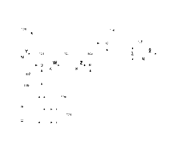
Fig. 1 is a generalized block diagram of a parametric reconstruction section
100, according to an example embodiment, adapted to reconstruct the plurality
of
audio signals X based on the downmix signal Y and associated wet upmix
coefficients P and dry upmix coefficients C. A pre-multiplier 101 receives a
time/frequency tile of the downmix signal Y and outputs an intermediate signal
W
computed by mapping the downmix signal linearly in accordance with a first set
of
coefficients, i.e. according to equation (3), wherein the first set of
coefficients is the
set of pre-decorrelation coefficients represented by the pre-decorrelation
matrix Q. A
decorrelating section 102 receives the intermediate signal Wand outputs, based
thereon, a decorrelated signal Z = [z1 === zic] . In the present example
embodiment,
the K channels of the decorrelated signal Z are derived by processing the K
channels
of the intermediate signal W, including applying respective all-pass filters
to the
channels of the intermediate signal W, so as to provide channels that are
mutually
uncorrelated, and with audio content which is spectrally similar to and is
also
perceived as similar to that of the intermediate audio signal W by a listener.
The
decorrelated signal Z serves to increase the dimensionality of the
reconstructed
version fe of the plurality of audio signals X, as perceived by a listener. In
the present
example embodiment, the channels of the decorrelated signal Z have at least
approximately the same energies or variances as that of the respective
channels of
the intermediate audio signal W. A wet upmix section 103 receives the wet
upmix
coefficients P as well as the decorrelated signal Z and computes a wet upmix
signal
by mapping the decorrelated signal Z linearly in accordance with the wet upmix
- 23 -
CA 02926243 2016-04-04
WO 2015/059152 PCT/EP2014/072568
coefficients P, i.e. according to equation (2), where the wet upmix signal is
denoted
by PZ. A dry upmix section 104 receives the dry upmix coefficients C and, in
parallel
to the pre-multiplier 101, also the time/frequency tile of the downmix signal
Y. The dry
upmix section 103 outputs a dry upmix signal, denoted by CY in equation (2),
computed by mapping the downmix signal Y linearly in accordance with the set
of dry
upmix coefficients C. A combining section 105 receives the dry upmix signal CY
and
the wet upmix signal PZ and combines these signals to obtain a
multidimensional
reconstructed signal 2 corresponding to a time/frequency tile of the plurality
of audio
signals X to be reconstructed. In the present example embodiment, the
combining
section 105 obtains the multidimensional reconstructed signal 2 by combining
the
audio content of the respective channels of the dry upmix signal CY with the
respective channels of the wet upmix signal PZ, according to equation (2). The
parametric reconstruction section 100 further comprises a converter 106 which
receives the wet upmix coefficients P and the dry upmix coefficients C, and
computes, according to the predefined rule given by equation (5), the first
set of
coefficients, i.e. the pre-decorrelation coefficients Q, and supplies the
first set of
coefficients Q to the pre-multiplier 101.
In the present example embodiment, the parametric reconstruction section
100 may optionally employ interpolation. For example, the parametric
reconstruction
section 100 may receive a plurality of values of the wet and dry upmix
coefficients
P, C, where each value is associated with a specific anchor point. The
converter 106
computes, based on values of the wet and dry upmix coefficients P,C associated
with
two consecutive anchor points, corresponding values of the first set of
coefficients Q.
The computed values are supplied to a first interpolator 107 which performs
interpolation of the first set of coefficients Q between the two consecutive
anchor
points, e.g. by interpolating a value of the first set of coefficients Q for
at least one
point in time comprised between the consecutive anchor points based on the
values
of the first set of coefficients Q already computed. The interpolation scheme
employed may for example be linear interpolation. Alternatively, steep
interpolation
may be employed, where old values for the first set of coefficients Q are kept
in use
until a certain point in time, e.g. indicated in the metadata encoded in the
bitstream B,
at which new values for the first set of coefficients Q are to replace the old
values.
Interpolation may also be employed on the wet and dry upmix coefficients P,C
themselves. A second interpolator 108 may receive multiple values of the wet
upmix
- 24 -
CA 02926243 2016-04-04
WO 2015/059152 PCT/EP2014/072568
coefficients and may perform time interpolation before supplying the wet upmix
coefficients P to the wet upmix section 103. Similarly, a third interpolator
109 may
receive multiple values of the dry upmix coefficients C and may perform time
interpolation before supplying the dry upmix coefficients C to the dry upmix
section
104. The interpolation scheme employed for the wet and dry upmix coefficients
P,C
may be the same interpolation scheme as employed for the first set of
coefficients Q,
or may be a different interpolation scheme.
Fig. 2 is a generalized block diagram of an audio decoding system 200
according to an example embodiment. The audio decoding system 200 comprises
the parametric reconstruction section 100 described with reference to Fig. 1.
A
receiving section 201, e.g. including a demultiplexer, receives the bitstream
B
transmitted from the audio encoding system 400 described with reference to
Fig. 4,
and extracts the downmix signal Y and the associated dry upmix coefficients C
and
wet upmix coefficients P from the bitstream B. In case the downmix signal Y is
encoded in the bitstream B using a perceptual audio codec such as Dolby
Digital or
MPEG AAC, the audio decoding system 200 may comprise a core decoder (not
shown in Fig. 2) configured to decode the downmix signal Y when extracted from
the
bitstream B. A transform section 202 transforms the downmix signal Y by
performing
inverse MDCT and a QMF analysis section 203 transforms the downmix signal Y
into
a QMF domain for processing by the parametric reconstruction section 100 of
the
downmix signal Y in the form of time/frequency tiles. Dequantization sections
204
and 205 dequantize the dry upmix coefficients C and wet upmix coefficients P,
e.g.,
from an entropy coded format, before supplying them to the parametric
reconstruction section 100. As described with reference to Fig. 4,
quantization may
have been performed with one of two different step sizes, e.g. 0.1 or 0.2. The
actual
step size employed may be predefined, or may be signaled to the audio decoding
system 200 from the encoder side, e.g. via the bitstream B.
In the present example embodiment, the multidimensional reconstructed audio
signal g output by the parametric reconstruction section 100 is transformed
back
from the QMF domain by a QMF synthesis section 206 and is then provided to a
renderer 207. In the present example embodiment, the audio signals X to be
reconstructed include audio object signals associated with time-variable
spatial
positions. Rendering metadata R, including spatial locators for the audio
objects, may
have been encoded in the bitstream B on an encoder side, and the receiving
section
- 25 -
CA 02926243 2016-04-04
WO 2015/059152 PCT/EP2014/072568
201 may extract the rendering metadata R and provide it to the renderer 207.
Based
on the reconstructed audio signals g and the rendering nnetadata R, the
renderer 207
renders the reconstructed audio signals g to output channels of the renderer
207 in a
format suitable for playback on a multi-speaker system 208. The renderer 207
may
for example be comprised in the audio decoding system 200, or may be a
separate
device which receives input data from the audio decoding system 200.
III. Equivalents, extensions, alternatives and miscellaneous
Further embodiments of the present disclosure will become apparent to a
person skilled in the art after studying the description above. Even though
the
present description and drawings disclose embodiments and examples, the
disclosure is not restricted to these specific examples. Numerous
modifications and
variations can be made without departing from the scope of the present
disclosure,
which is defined by the accompanying claims. Any reference signs appearing in
the
claims are not to be understood as limiting their scope.
Additionally, variations to the disclosed embodiments can be understood and
effected by the skilled person in practicing the disclosure, from a study of
the
drawings, the disclosure, and the appended claims. In the claims, the word
"comprising" does not exclude other elements or steps, and the indefinite
article "a"
or "an" does not exclude a plurality. The mere fact that certain measures are
recited
in mutually different dependent claims does not indicate that a combination of
these
measures cannot be used to advantage.
The devices and methods disclosed hereinabove may be implemented as
software, firmware, hardware or a combination thereof. In a hardware
implementation, the division of tasks between functional units referred to in
the above
description does not necessarily correspond to the division into physical
units; to the
contrary, one physical component may have multiple functionalities, and one
task
may be carried out by several physical components in cooperation. Certain
components or all components may be implemented as software executed by a
digital signal processor or microprocessor, or be implemented as hardware or
as an
application-specific integrated circuit. Such software may be distributed on
computer
readable media, which may comprise computer storage media (or non-transitory
media) and communication media (or transitory media). As is well known to a
person
skilled in the art, the term computer storage media includes both volatile and
- 26 -
CA 02926243 2016-04-04
WO 2015/059152 PCT/EP2014/072568
nonvolatile, removable and non-removable media implemented in any method or
technology for storage of information such as computer readable instructions,
data
structures, program modules or other data. Computer storage media includes,
but is
not limited to, RAM, ROM, EEPROM, flash memory or other memory technology,
CD-ROM, digital versatile disks (DVD) or other optical disk storage, magnetic
cassettes, magnetic tape, magnetic disk storage or other magnetic storage
devices,
or any other medium which can be used to store the desired information and
which
can be accessed by a computer. Further, it is well known to the skilled person
that
communication media typically embodies computer readable instructions, data
structures, program modules or other data in a modulated data signal such as a
carrier wave or other transport mechanism and includes any information
delivery
media.
- 27 -