Note: Descriptions are shown in the official language in which they were submitted.
CA 02926274 2016-04-07
=
METHOD AND APPARATUS FOR THE RECOVERY OF DRILLING FLUID FROM
SHAKER TAILINGS DURING ACTIVE DRILLING
CROSS-REFERENCE TO RELATED APPLICATIONS
[0001] Not applicable.
STATEMENT REGARDING FEDERALLY SPONSORED
RESEARCH OR DEVELOPMENT
[0002] Not applicable.
BACKGROUND
Technical Field
[0003] This disclosure relates generally to apparatus used in solids
separation techniques, and
in particular, in the separation of drill cuttings from drilling fluid. More
particularly, it relates to
methods and apparatus for the recovery of valuable drilling fluid from the
tailings that come off
of conventional shaker machines which make a first separation of drilling
fluid from drill
cuttings at the drilling site.
General Background
[0004] For the ultimate recovery of oil and gas, boreholes are typically
drilled by rotating a
drill bit that is attached to the bottom of a drill string. With weight
applied to the drill string,
the rotating drill bit engages the earthen formation and proceeds to form a
borehole toward a
target zone. This produces large quantities of rock particles, typically
referred to as "drill
cuttings" or "drilled solids." To aid in the removal of drill cuttings, as is
necessary to form the
borehole, pressurized drilling fluid is continuously pumped down the drill
string to the drill bit.
The fluid exits through nozzles in the bit and returns to the surface carrying
with it the drill
cuttings.
[0005] When it returns to the surface, the fluid is a slurry of fine solids
that are important
components of the drilling fluid, as well as the coarser drill cuttings, and
the base liquid. The
base liquid portion of the drilling fluid may be oil or water. But in either
case, it is highly
desirable to recover and reuse as much of the drilling fluid as possible
because it is expensive. It
is also desirable to remove the drilling fluid from the coarse drill cuttings
so that the cuttings can
be disposed of in a cost-effective and environmentally safe manner.
1
CA 02926274 2016-04-07
[0006] At the surface, some of the drill cuttings are separated from the
drilling fluid by
vibratory screening machines, commonly referred to as "shaker machines." The
separated
cuttings or "shaker tailings" are still wetted by the drilling fluid. Although
these tailings may be
discarded, they can contain substantial amounts of the oil or water-based
drilling fluid. The
residue on oil based cuttings consists of an emulsion of aqueous salt solution
in a light mineral
oil base. In some instances, these cuttings have been collected and mixed with
a stabilizing
product and shipped to a processing facility for oil or water residue removal,
however, this adds
significant cost due to the transport and processing. Additional added costs
arise from the need to
add new drilling fluid or fluid constituents in order to recover for the lost
volume of drilling
fluid.
[0007] Cleaning systems have been developed for reducing the hydrocarbon
content in shaker
tailings at the drilling site. Some such systems employ an initial washing
technique using
chemicals that are potentially hazardous to workers. Others use acids,
surfactants, and/or
dispersants, followed by centrifugal separation and discharge of the "cleaned"
solids. While
theoretically producing cleaner solids, the technique results in the secondary
problem of
producing large volumes of oil-contaminated wash water for disposal.
[0008] Another on-site system involves moving the shaker tailings by augers
and conveyors
and then grinding the solids, producing ultra-fine solids that are then
slurried by agitators and
processed with centrifuges. These systems, however, have large footprints and
necessitate added
set up, maintenance and safety procedures. Further, the mechanical forces
these systems employ
degrade (make smaller) the drilled solids, and then returns them to the active
drilling fluid. The
smaller particles, called low gravity solids or ultra-fines, can lower
drilling rates, yet they cannot
be removed by the usual solids control equipment present at the rig. Thus, the
drilling fluid to
which these ultafines have been added must be blended with new base oil or
water in order to
provide the drilling fluid with the proper density and consistency. The needed
blending and fluid
maintenance can substantially increase cost.
[0009] Some thermal methods have been used which employ either thermal
destruction of the
hydrocarbons associated with the cuttings, or thermal evaporation of the oil,
followed by
condensation and recovery of oil portions. Such systems have suffered the
disadvantages of high
mechanical wear, corrosion, and have also had a high energy demand due, in
large part, to the
necessity of evaporating all water associated with the cuttings. Further,
these systems are
2
CA 02926274 2016-04-07
generally set up away from the drilling site, thereby adding transportation
cost and creating the
possibility of spills.
[0010] Thus, there remains a need in the art for methods, systems and
apparatus for recovering
valuable drilling fluid from shaker tailings in a safe, efficient, and cost
effective manner.
Automated recovery systems, methods and apparatus that can be employed at the
drilling site
and that work in concert with standard solids control equipment present at the
rig, have a small
footprint, and that return fluid to the active drilling fluid system
continuously and without the
introduction of ultra-fines, would be especially welcomed by the industry.
SUMMARY OF THE DISCLOSURE
[0011] Disclosed is a system and method for recovering drilling fluid from
shaker tailings that
may be employed at the drilling site and during active drilling operation.
[0012] In one embodiment, the system includes a hopper comprising an interior
chamber, a
plurality of nozzles configured to spray fluid into the chamber, and a cover
that is pivotable
between a first position in which the chamber is uncovered and a second
position in which the
chamber is covered. A conveying surface on the cover forms an acute angle with
respect to the
direction of gravity when the cover is in the second position. The system
further includes a
holding tank for containing a volume of drilling fluid, a first pump
configured to convey drilling
fluid from the holding tank to the nozzles, and a second pump configured to
convey the mixture
of drill cuttings and drilling fluid from the hopper chamber to a first
centrifuge. The first
centrifuge is configured such its effluent is conveyed to the holding tank. A
first level detector is
provided and configured to sense the level of the mixture in the hopper
chamber and to provide
an output to a control system. A drive motor is coupled to the hopper cover
and configured to
move the cover between the first position and the second position in response
to a control signal
provided by the control system. The drive motor moves the hopper cover to the
second position
when the level in the hopper chamber reaches a first predetermined level so
tailings are diverted
by the cover's conveying surface and not deposited within the hopper.
[0013] In one embodiment, the control system is configured to control the
speed of at least one
of the first and second pumps in response to the output from the first level
detector. The system
may also include a third pump configured to convey drilling fluid from the
holding tank to the
suction side of a forth pump, wherein the discharge side of the forth pump is
configured to
3
CA 02926274 2016-04-07
convey drilling fluid to a second centrifuge. The second centrifuge may be
configured such that
the effluent from the second centrifuge is conveyed to a rig tank.
[0014] In one embodiment, the system includes a second level detector
configured to sense the
fluid level in the holding tank and provide an output to the control system in
response to the
sensed fluid level, wherein the control system is configured to turn on the
third pump when the
level in the holding tank rises to a predetermined level. The control system
may be further
configured to turn off at least one of the first and second pumps when the
level in the hopper
chamber reaches a second predetermined level. The first level detector may be
one that provides
an output signal that is proportional to the level of the mixture detected in
the hopper chamber.
[0015] In one embodiment, the system further comprises a vibratory screening
machine
configured to convey from a screening surface to the hopper chamber the
mixture of drill
cuttings and drilling fluid, the hopper being positioned relative to the
screening surface such that
the mixture is conveyed by gravity into the hopper chamber when the cover is
in the first
position and the mixture is conveyed by gravity on to the conveying surface of
the cover when
the cover is in the second position.
[0016] In one embodiment, the hopper chamber comprises a bottom that slopes
from a high
end toward a low end, and wherein the suction side of the second pump is in
fluid
communication with the chamber at the low end.
[0017] In one embodiment, the first and/or the second pumps are low shear
pumps, such as
vortex pumps.
[0018] A method for recovering drilling fluid from a mixture that includes
drill cuttings and
drilling fluid is disclosed and includes: conveying into an open hopper
chamber a feed stream
comprising a mixture of drill cuttings and drilling fluid; pumping a portion
of the mixture from
the hopper chamber to a first centrifuge; conveying the drilling fluid
effluent from the first
centrifuge to a fluid holding tank; pumping fluid from the fluid holding tank
into the hopper
chamber through a plurality of nozzles; using a cover, closing the hopper
chamber when the level
of the mixture in the hopper chamber reaches a first predetermined level and
thereby diverting
the feed stream outside the chamber.
[0019] In an embodiment, the method further includes comprising stopping the
pumping into
the first centrifuge when the level of the mixture in the hopper chamber is
below a second
4
CA 02926274 2016-04-07
predetermined level and/or stopping the pumping from the holding tank into the
hopper chamber
through the nozzles when the level in the hopper chamber is below a second
predetermined level.
[0020] In one embodiment, the method further includes pumping fluid from the
holding tank to
a second centrifuge and conveying the effluent from the second centrifuge to a
rig tank of an
active drilling fluid system.
[0021] In one embodiment, the method further includes monitoring the level of
mixture in the
hopper chamber, and changing the pumping speed of at least one of the pumps in
response to a
change in the monitored level of the mixture in the hopper chamber. In an
embodiment, the
method includes simultaneously operating the first pump at a first speed and
the second pump at
a second speed and, in response to a change in level of the mixture in the
hopper chamber,
changing the speed of at least one of the pumps to a third speed.
[0022] In one embodiment, the method includes monitoring the level of mixture
in the hopper
chamber during active drilling operations, and continuing active drilling
operations after the
cover has closed the hopper chamber.
[0023] Disclosed too is apparatus for recovering drilling fluid from a mixture
that includes drill
cuttings and drilling fluid where the apparatus comprises: a hopper having a
chamber, a chamber
opening, and a cover, the cover being pivotable between an open position in
which the chamber
is open to receiving a flow of the mixture, and a closed position in which the
chamber is closed
to receiving a flow of the mixture. The cover includes a cover having a
conveying surface that,
when the cover is in the closed position, forms an acute angle with respect to
the direction of
gravity. The apparatus includes a control system responsive to the level of
the mixture in the
chamber and a motor mechanically coupled to the cover and electrically coupled
to the control
system, the control system being configured to cause the motor to rotate the
cover to the closed
position when the level of the mixture in the chamber reaches a predetermined
level.
[0024] In one embodiment, the apparatus includes an elongate support structure
or skid
coupled to the hopper and having a footprint; a low shear pump supported by
the support
structure and configured such that the suction side of the pump is in fluid
communication with
the chamber at the second end of the hopper; a plurality of nozzles configured
to spray fluid into
the chamber; and a conduit on the support structure configured to supply fluid
to the nozzles. In
one embodiment, the cover is rotatably connected to each end of the hopper and
configured to
pivot about an axis of rotation.
CA 02926274 2016-04-07
[0025] In one embodiment, the cover is coupled to the hopper such that the
axis of rotation of
the cover is substantially parallel to, but laterally offset from, a vertical
plane that bisects the
hopper.
[0026] In one embodiment, the cover is coupled such that the cover rotates
more than 90
degrees but less than 180 degrees when moving from the open position to the
closed position,
and in one embodiment, the conveying surface forms an angle with respect to
the direction of
gravity that is not greater than 59 degrees when in the closed position.
[0027] Thus, embodiments described herein include various combinations of
features intended
to address certain shortcomings associated with certain prior devices,
systems, and methods. The
various combinations and features described above, as well as others, will be
readily apparent to
those skilled in the art upon reading the following detailed description, and
by referring to the
accompanying drawings.
BRIEF DESCRIPTION OF THE DRAWINGS
[0028] For a detailed description of the disclosed exemplary embodiments of
the invention,
reference will now be made to the accompanying drawings in which:
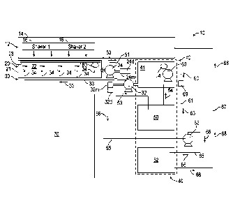
[0029] Figure 1 is a schematic view of a system for the recovery of drilling
fluid from shaker
tailings;
[0030] Figure 2 is a perspective view of a collection hopper module or skid,
which can be
employed as a portion of the system disclosed in Figure 1;
[0031] Figure 3 is a front elevation view of the collection hopper module of
Figure 2;
[0032] Figure 4 is a rear elevation view of the collection hopper module of
Figure 2;
[0033] Figures 5 and 6 are end elevation views of the collection hopper module
of Figure 2;
[0034] Figure 7 is a top or plan view of the collection hopper module of
Figure 2;
[0035] Figure 8A is an end elevation view of the collection hopper module of
Figure 2 shown
with the hopper cover in the open position, and with the hopper positioned to
receive shaker tailings
from an adjacent shaker machine;
[0036] Figure 8B is an end elevation view of the collection hopper module of
Figure 8A shown
here with the hopper cover in the closed position in which the hopper chamber
is covered, and with
the cover diverting shaker tailings.
[0037] Figure 9 is a perspective view of the collection hopper skid of Figure
2, with the hopper
shown in an elevated position.
6
CA 02926274 2016-04-07
[0038] Figure 10 is a schematic diagram of a control system 300 that can be
employed with the
recovery system of Figure 1.
DETAILED DESCRIPTION OF DISCLOSED EXEMPLARY EMBODIMENTS
[0039] This disclosure is directed to and describes various exemplary
embodiments. The
discussion of any embodiment is meant only to be exemplary of that embodiment,
and is not
intended to intimate that the scope of this disclosure, including the claims,
is limited to that
embodiment. The drawing figures are not necessarily to scale. Certain depicted
features and
components may be shown exaggerated in scale or in somewhat schematic form,
and some details
of conventional elements may not be shown in interest of clarity and
conciseness.
[0040] In the following discussion and in the claims, the terms "including"
and "comprising" are
used in an open-ended fashion, and thus are to be interpreted to mean
"including, but not limited
to... ." Also, the term "couple" or "couples" is intended to mean either an
indirect or direct
connection. Thus, if a first device couples to a second device, the connection
between the two
devices may be through a direct connection between the two devices, or through
an indirect
connection, one made via other intermediate devices, components, and
connections. In addition, if
the connection transfers electrical power or signals, whether analog or
digital, the coupling may
comprise wires or a mode of wireless electromagnetic transmission, for
example, radio
frequency, microwave, optical, or another mode. So too, the coupling may
comprise a magnetic
coupling or any other mode of transfer known in the art, or the coupling may
comprise a
combination of any of these modes. Further, as used herein, the terms "axial"
and "axially"
generally mean along or parallel to a given axis (e.g., a central axis of a
body), while the terms
"radial" and "radially" generally mean perpendicular to a given axis. For
example, an axial
distance refers to a distance measured along or parallel to the given axis,
and a radial distance
means a distance measured perpendicular to the axis.
Recovery System ¨ Overview
[0041] Referring first to Figure 1, fluid recovery system 10 is shown in
schematic form and
generally includes: a rig tank module 12; a collection hopper skid or module
20 that includes hopper
21, diverter lid or cover 23, and hopper pump 24; a jetting system 30 that
includes jetting pump 32;
a fluid processing module 40 that includes fluid recovery tank 41 and
centrifuges 50, 52. Fluid
recovery system 10 further includes transfer pump 60, feed pump 62 and
disposal bin 70. The
system is controlled by a control system 300, best shown in Figure 10, and may
be employed while
7
CA 02926274 2016-04-07
active drilling operations are ongoing. That is, system 10 may be employed so
as to return to the
active drilling fluid system the drilling fluid that has been recovered from
the shaker tailings.
Rig Tank Module
[0042] Referring to Figure 1, rig tank module 12 is shown to include one or
more tanks 14 for
containing a volume of drilling fluid, and may be referred to herein as a "mud
tank" or a "rig tank."
The function of the rig tank 14 is to maintain a supply of drilling fluid that
is of sufficient
cleanliness, density and other needed qualities, making it ready to be pumped
down hole to facilitate
the drilling operation. Suspended on a deck above mud tank 14 are one or more
vibratory screening
machines 16, also commonly referred to as "shaker machines" or "shakers." In
the rig tank module
12, two such shakers 16 are shown, however, fewer or more shakers may be
employed depending
upon the application. The shakers may be any conventional shaker, such as a
Brandt King Cobra.
[0043] As is conventional in this field, the shakers 16 include vibratory
screening surfaces which,
during drilling operation, receive a slurry of solids-laden drilling fluid
that, after being pumped
down hole, returns to the surface carrying drilled solids. The slurry is
deposited on the vibrating
screens of the shakers. The drilling fluid, along with solids that are small
enough to pass through the
screen openings, fall by gravity through the screens and into the rig tank 14
for reuse in the active
drilling fluid system without further processing. The drill cuttings that are
too large to pass through
the openings in the screen, are transported along the screen surface by the
vibration that is imparted
to them by the shaker machine 16. The cuttings transported along the screen
surfaces include a
volume of drilling fluid that remains attached to the solids, and these
"shaker tailings" are conveyed
off the shaker machine 16 and allowed to fall by gravity toward the collection
hopper module 20 so
they can be recovered at the drilling site and during active drilling
operations.
Collection Hopper Module
[0044] The components and construction of hopper module 20 are described in
greater detail
below, particularly with reference to Figures 2-7. However, for the present
purpose of conveying an
understanding of the overall operation of fluid recovery system 10, and
referring still to Figure 1, it
is to be understood that hopper module 20 includes a trough-like hopper 21,
and a pivotable hopper
cover 23. Cover 23 is configured to be rotatable between a first or open
position, which allows the
shaker tailings to fall by gravity from the shaker machines 16 into the open
hopper chamber 22, and
a second or closed position, in which the cover 23 covers the chamber 22 and
thereby diverts the
falling flow of shaker tailings outside the hopper chamber 22 and to disposal
bin 70.
8
CA 02926274 2016-04-07
[0045] Aided in part by the shape and slope of the hopper 21, and by jetting
system 30, all of
which are described in more detail below, the shaker tailings that are
deposited in hopper 21 are
conveyed toward the lower end of hopper 21 that is adjacent to hopper pump 24.
The suction end of
hopper pump 24 is in fluid communication with the hopper chamber 22 and thus
pump 24 draws the
shaker tailings from chamber 22 and discharges them to the feed end of a
centrifuge 50, the tailings
being conveyed along feed line 51 in the direction shown by arrows 53.
[0046] As used herein, the term "low shear pump" means a pump that imparts low
or minimal
shear forces to the mixture or slurry being conveyed through the pump and
limits the formation of
ultra-fines. That is, excessive shear causes the drilled solids to degrade and
results in ultra-fines
becoming part of the recovered drilling fluid, a highly undesirable condition
as, when they are
introduced into the active drilling fluid system, they hamper efficient
drilling, are not easily
removed, and typically require that substantial additional quantities of new
drilling fluid be added to
the active system. Low shear pumps include vortex pumps, a design in which the
impeller is
recessed in the pump body so as to be out of contact with the main stream of
fluid flow, thereby
minimize solids degradation from occurring due to the entrained solids
impacting the impeller.
In one embodiment, hopper pump 24 is low shear pump, and more particularly is
a vortex pump,
such as a Mission Magnum Vortex pump manufactured by National Oilwell Varco. A
vortex
pump, having its impeller outside the main flow area, produces a primary
vortex or swirling
action that, in turn, creates a secondary vortex in the main flow path the
produces fluid flow
along the desired path. Other low shear pumps include eccentric disc pumps,
and progressive
cavity pumps.
Jetting System
[0047] Jetting system 30 includes jetting pump 32, a primary feed line or
conduit 33, and a
plurality of branch conduits 31, each conveying fluid from conduit 33 to a
nozzle 34 that is mounted
inside hopper chamber 22. As explained in more below, the suction side of
jetting pump 32 is in
fluid communication with fluid recovery tank 41. The discharge from jetting
pump 32 is conveyed
via primary feed line 33 in the direction of arrow 35 to each of the nozzles
34. In one embodiment,
jetting pump 32 is a low shear pump vortex pump such as a Mission Magnum
Vortex pump
manufactured by National Oilwell Varco. As with hopper pump 24, it is
desirable to minimize
solids degradation that might occur through the application of a typical feed
pump that is not a
low shear pump.
9
CA 02926274 2016-04-07
Fluid Processing Module
[0048] Fluid processing module 40 includes recovery tank 41 and centrifuges
50, 52. Tank 41
may also be referred to as a fluid holding tank as it receives and holds
drilling fluid that has been
recovered via a first centrifuge process. In one embodiment, tank 41 and
centrifuges 50, 52 are
mounted on the same skid or other support structure, one that is dimensioned
to fit on a truck or
trailer bed that can be transported on the highway. In one embodiment, the
centrifuges 50, 52 are
aligned on the support structure, end to end, with the fluid recovery tank 41
mounted above the
aligned centrifuges.
[0049] Regardless of the physical arrangement, fluid recovery tank 41 is a
vessel configured to
hold a supply of drilling fluid that has undergone at least a first "cleaning"
by virtue of the shaker
tailings first passing through centrifuge 50. That is, as described above,
hopper pump 24 conveys
the shaker tailings to the feed end of centrifuge 50. Centrifuge 50 is a
variable decanting centrifuge,
such as Brand model number 2172. In a well understood manner, the shaker
tailings entering
centrifuge 50 are divided into a liquid component and a solids component. The
liquid component, or
effluent, is conveyed to fluid recovery tank 41 via conduit 54 while the
solids are removed from the
mixture and transmitted to disposal bin 70 by mechanical conveyor and/or
gravity feed. In this
manner, the shaker tailings undergo a first process by which the valuable
drilling fluid otherwise
attached to the drilled solids is recovered and conveyed to recovery tank 41
for use with jetting
system 30, or for further processing as explained below.
[0050] Transfer pump 60, which may be a positive displacement pump, such as
Model 34401
Moyno pump manufactured by National Oilwell Varco, is configured to have its
suction side in
fluid communication with recovery tank 41. Pump 60 is driven by a 2 HP motor
60m (Figure 10)
and, in one embodiment, is physically located above tank 41. When activated,
pump 60 discharges
fluid from recovery tank 41 to the suction side of feed pump 62 along line or
conduit 61, the drilling
fluid being conveyed in the direction shown by arrows 63. A flow meter 69 is
provided in line 61
for measuring the volume of drilling fluid that has been recovered from the
shaker tailings and
processed by centrifuge 50.
[0051] Feed pump 62, which may be a 25 HP pump such as a Mission Magnum pump,
has its
suction side also in fluid communication with rig tank 14 via conduit 55,
allowing pump 62 to draw
fluid from rig tank 14 in the direction shown by arrow 56. In normal
operation, fluid is drawn from
tank 41, however, a valve (not shown) is provided to select feeds to pump 62
such that, for
CA 02926274 2016-04-07
maintenance to line 61, pump 60 or flow meter 69, fluid flow may be diverted
through line 55.
Feed pump 62 is driven by a 25 HP motor 62m (Figure 10) and has its discharge
side in fluid
communication with the feed end of centrifuge 52 via conduit 65, the fluid
being conveyed to
centrifuge 52 in the direction shown by arrows 66. Centrifuge 52 is a
decanting centrifuge, such as
Brandt model number 2172. In this arrangement, the drilling fluid conveyed
either from recovery
tank 41 or from rig tank 14 undergoes a secondary removal process in that the
mixture entering
centrifuge 52 is divided into a liquid component and a solids component. The
liquid component, or
effluent, is conveyed to rig tank 14 via conduit 67 in the direction shown by
arrows 68 and thus
becomes part of the fluid of the active drilling fluid system. The solids
removed by centrifuge 52
are transmitted to disposal bin 70 by mechanical conveyor and/or gravity. In
this manner, drilling
fluid having already been "cleaned" at least via undergoing the centrifuge
process from centrifuge
50, undergoes a further "cleaning" by centrifuge 52.
Disposal Bin 70
[0052] As has been described, the solids removed by centrifuges 50, 52, are
transported to
disposal bin 70. Likewise, during conditions in which hopper cover 23 is
closed, as described
below, shaker tailings that would otherwise fall into hopper chamber 22 for
fluid removal are
diverted by cover 23 into disposal bin 70. The material in disposal bin 70 may
then be gathered and
treated or disposed of via conventional methods.
Collection Hopper
[0053] Drilling hydrocarbon wells requires the use of large, complex
assemblies of machinery
and systems. Most land-based drilling rigs are designed to be transported by
trucks and trailers,
and thus are made to disassemble into skid-mounted modules sized so as to be
quickly and easily
loaded onto, transported by, and offloaded from a trailer by cranes, winches
and the like. This
modular approach helps minimize the time needed for rig up and rig down
operations. Highway-
transportable hopper skid or module 20, best shown in Figures 2 and 9,
includes support structure
100 configured to support hopper 21, hopper pump 24, pump drive motor 24m, and
the fluid
delivery conduits of jetting system 30. Support structure 100 forms an
equipment skid that may be
employed to raise and lower hopper 21 as needed to best fit the hopper chamber
22 beneath the
shaker machines 16 to receive the tailings. Figure 2 shows the skid and hopper
in their lowest
positions, and Figure 9 depicts them in their highest position.
11
CA 02926274 2016-04-07
[0054]
Support structure 100 includes lower and upper frames 101a, b, each including
longitudinal channel members 102 and transverse members 103 extending
therebetween.
Longitudinal members 102 include apertures 105 to provide access for lifting
and tie down.
Extending upwardly from frame 101b are vertical support members 104, and
extending upwardly
from frame 101a are vertical supports 106 that are received by and telescope
within members 104.
In this embodiment, vertical support members 104 and 106 are formed of tubular
steel with square
cross sections. To position hopper at the appropriate height, frame 101a is
held on grade, and frame
101b is lifted and separated from frame 101a. At the appropriate height, pins
(not shown) are placed
through aligned holes 107, 108 that are provided in vertical supports 104, 106
respectively. In one
embodiment, frame 101b is maintained at a position of up to 18 inches above
frame 101a. Frame
101b includes an open enclosure formed by upwardly extending walls 109 beneath
hopper 21 to
capture any spillage or leaks.
[0055] Referring now to Figures 2, and 5-7, hopper 21 includes a pair of
hopper ends 110, 112
coupled to a hopper bottom 114 and to a pair of opposing and elongate sides
116. Sides 116 extend
between and are attached to the ends 110, 112, and are attached the hopper
bottom 114.
Collectively, hopper bottom 114, ends 110, 112, and sides 116 define hopper
chamber 22 that is to
receive the shaker tailings from shaker machines 16. The opening 118 of hopper
chamber 22
through which the shaker tailings are received is defined, in part, by the
upper edges 117 (Figure 2)
of hopper sides 116. Vertical support members 104 are attached to hopper sides
116 adjacent the
chamber opening 118, i.e., adjacent the upper edges 117 of the elongate sides
116.
[0056] From chamber opening 118 to the hopper bottom 114, sides 116 slope
inwardly toward
one another and toward the hopper centerline 170 (Figure7). Further, the
hopper bottom 114 slopes
from end 110 toward end 112. In this configuration, end 110 may be referred to
as the "high end"
whereas end 112 may be referred to as the "low end." The suction side of
hopper pump 24 is in
fluid communication with the hopper chamber 22 at a location adjacent low end
112 via conduit
119. Given this configuration, shaker tailings that have been deposited into
hopper 21 are conveyed
by gravity towards the hopper longitudinal centerline 170 and the vertical
plane 115 (best shown in
Figures 5, 6) that contains centerline 170 (Figure 7), and are also conveyed
from high end 110 to
low end 112 by momentum supplied by jetting pump 32, nozzles 34 and gravity.
In this manner, the
hopper chamber 22 defines a trough for conveying shaker tailings towards the
suction end of hopper
pump 24. A course screen or grate 113 is positioned within chamber 22 adjacent
opening 118 and is
12
CA 02926274 2016-04-07
disposed between sides 116 and ends 110, 112, Grate 113 serves to prevent
debris from entering the
trough and being conveyed toward the intake of hopper pump 24 and, in one
embodiment, has 2
inch openings.
[0057] Attached to each hopper end 110, 112 is an upwardly extending cover
mount 120, 122 for
supporting pivoting cover 23. In one embodiment, each mount 120, 122 is
generally triangular in
shape and tapers from a wider portion that is adjacent to the hopper sides
116, to a narrower
portion 121 that extends to a position above the chamber 22.
[0058] Hopper cover 23, best described with reference to Figure 2, includes
diverter plate 130, a
pair of connector plates 132, and a pair of angled cover ends 134. Diverter
plate 130 includes a
generally planar conveying surface 131, a pair of inwardly-tapered edges 137
and a lateral edge 138
that intersects tapered edges 137. Connector plates 132 are spaced apart and
connected to diverter
plate 130 so as to extend in a direction generally perpendicular from the
conveying surface 131.
Each connector plate 132 is generally triangular in shape and tapers from a
wider portion that is
adjacent to diverted plate 130 to a narrower portion 133 that extends to a
position distal to the
plate 130. Cover 23 also includes a pair of angled cover ends 134, each being
coupled to and
extending between a connector plate 132 and a tapered edge 137 of diverter
plate 130.
[0059] An elongate support member 140 extends between and is connected to each
connector
plate 132 and also to diverter plate 130. A transverse support member, such as
channel 142, is
provided and coupled to support member 140 and diverter plate 130, and extends
to edge 138 of
diverter plate 130. Support members 140, 142 provide added rigidity to cover
23. Additional
support members, such as channel 144 (Figure 3), may be provided to further
increase the
rigidity of cover 23.
[0060] Referring now to Figures 2, 5-6, cover 23 is rotatably connected to
each end of the
hopper 21, allowing cover 23 to rotate or pivot relative to hopper 21. In more
detail, each
connector plate 132 of cover 23 is disposed inside and adjacent to one of the
cover mounts 120,
122. Pin members 160 extend through aligned apertures that are formed in
mounts 120, 122. The
pins 160 and receiving apertures are axially aligned so as to define an axis
of rotation 162 about
which cover 23 is permitted to pivot or rotate. In the embodiment shown, each
pin 160 is rigidly,
non-rotatably, fixed to a connector plate 132 and is allowed to rotate within
the aperture formed in
the adjacent cover mount 120, 122. Also, in the embodiment shown, the pin 160
that is disposed
through mount 122 at low end 112 of hopper 21 is motor-driven, such that, the
rotation of the pin
13
CA 02926274 2016-04-07
160 extending through mount 122 will cause rotation of cover 23 in the
direction shown by arrows
150. Motor 163, best shown in Figure 5 may be, for example, a 1 / 2 HP motor
that, via gear box
164, chain 165 and gear 166, rotates pin 160. In the embodiment shown, motor
163 is an electric
motor, but a hydraulic motor may alternatively be employed. Further, although
the embodiment
depicted and described above employs only one driven pin, in other
embodiments, each pin 160
may be driven, and pins 160 may be driven by a single motor via appropriate
linkages, or each
driven by a dedicated motor.
[0061] As best shown in the end views of Figures 5, 6, the shape and position
of cover mounts
120, 122 and connector plates 132, and the positioning of pins 160, cooperate
to attach cover 23 to
hopper 21 such that the cover's axis of rotation 162 is laterally offset by a
distance D from the
hopper's longitudinal centerline 170, and the vertical plane 115 that passes
through and contains
hopper centerline 170 (Figure 7). As explained in more detail below, cover 23
need not pivot or
rotate 360 degrees about axis 162. In one embodiment, the degree of rotation
is less than 180
degrees, and in another, is approximately only 135 degrees.
[0062] Mounted in hopper chamber 22 is a level detector 180, shown
schematically in Figure 1.
Level detector 180, which may be, for example, model number CLIS-NOV-0100_as
manufactured
by FPI Sensors International provides to the control system 300 an output
signal that is proportional
to the level of tailings detected in hopper chamber 22. The control system 300
receives the output
signal from the level detector 180 and speeds up or slows down the speed of
the pumps 24, 32,
appropriately, as described in more detail below.
Control System 300
[0063] A control system 300 is provided to control the level of shaker
tailings contained within
hopper 22, to control the level of fluid in fluid recovery tank 41, to
appropriately control the rotation
of hopper cover 23, control the operation of centrifuges 50, 52, and for other
control functions. As
schematically represented in Figure 10, control system 300 receives inputs
from sensors, detectors,
and switches, processes the received signals to determine the appropriate
action to be taken, and
then outputs command signals to effect the proper control function. For
example, the output signals
include signals to start/stop motors, control variable frequency drives and
thus pump speeds, and
other functions. Control system 300 comprises a plurality of conventional
components electrically
coupled together, such as a digital computer, various solid state controllers,
motor starters, solid
state and electromagnet relays, and the like.
14
CA 02926274 2016-04-07
100641 As shown schematically in Figure 1 and 9, hopper pump 24 is driven by
AC motor 24m
that, in one embodiment is a 25 HP motor. Likewise, jetting pump 32 is driven
by AC motor 32m
that, in one embodiment is a 2 HP motor. Motors 24m and 32m may be controlled
by separate
variable frequency drives 24d, 32d respectively and which may each be a Model
Number A1000
drive as manufactured by Yaskawa Wermac of Calgary, Alberta Canada. By
controlling the speed
of motors 24m and 32m, the speeds of pumps 24, 32 and their rates of fluid
conveyance are likewise
controlled.
100651 It is desirable to control the level of shaker tailings in hopper
chamber 22. Control system
300 receives and monitors the output signal from level detector 180 in hopper
chamber 22. When
the level of tailings in hopper 22 is at a first predetermined "high" level
that indicates a sufficient
volume is present for fluid recovery, the control system 300 will cause the
variable speed drive 24d
controlling the speed of hopper pump 24 to pump at relatively high speed and
thus to pump a
relatively high volume of shaker tailings to centrifuge 50 for processing.
Likewise, when the level
in hopper chamber 22 is "high," the control system 300 will cause the variable
speed drive 32d
controlling the speed of jetting pump 32 to pump at relatively high speed and
thus to pump a
relatively high volume of fluid to the nozzles 34 in hopper chamber 22. A
relatively constant and
controlled level in hopper chamber 22 is desired, thus the control system 300
is programmed to
speed up or slow down the rpm's of pumps 24, 32 to maintain a desired level.
In one embodiment,
the speed of pump 24 is manually set at a first predetermined speed. The
control system 300 then
regulates the level of tailings in hopper chamber 22 by increasing or
decreasing the rpm of the
jetting pump 32.
100661 It is further desirable to control the level of fluid in the fluid
recovery tank 41. Mounted in
recovery tank 41 is a level detector 64, such as a float switch, shown
schematically in Figures 1 and
9. Level detector 64, which may be, for example, model number LS-NOV-1025 as
manufactured
by FPI Sensors International, provides an output signal to the control system
300 indicative of the
level in tank 41. When the level detector 64 detects that the fluid in tank 41
has reached a first
predetermined level, i.e., where there is sufficient fluid in the recovery
tank, the control system 300
turns on transfer pump 60 so as to convey fluid from the recovery tank 41 to
the suction side of feed
pump 62. On the occasion that the fluid level within recovery tank 41 drops to
a second
predetermined or "low" level, the signal from level detector 64 initiates the
control system 300 to
turn off transfer pump 60 so that level in recovery tank 41 can increase. On
the occasion that the
CA 02926274 2016-04-07
fluid level within recovery tank 41 increases to another predetermined level
that has been deemed
abnormally high, the control system 300 is set to actuate an alarm that
signals rig personnel to take
appropriate manual action.
[0067] The control system 300 is also configured to actuate motor 163 that
controls the
rotation and thus the position of cover 23 and to move the hopper cover 23
from the open
position to the closed position. If it is determined that the level of shaker
tailings within hopper
chamber 22 is too high, i.e. reaches a second predetermined "high" level,
motor 163 is actuated
to move the cover 23 to the closed position. Likewise, motor 163 may be
actuated to move the
cover 23 to the open or closed position by manually actuating a control switch
CS, shown in
Figure 10. A pair of limit switches LS1, LS2 (Figure 10) are mounted on the
hopper 21 and their
outputs coupled to the control system 300. Upon the cover 23 reaching a
predetermined "open"
position (as shown in Figure 8A), or predetermined "closed" position (Figure
8B), the
appropriate limit switch will signal the control system 300, which will, in
turn, deactivate motor
163 so that cover 23 does not rotate further and exceed the desired angular
position. Further,
upon failure of either variable speed drive 24d, 32d or their associated
motors or pumps, control
system 300 will cause cover 23 to close so drilling operations can continue
uninterrupted even
though drilling fluid will not be recovered by system 10 in that situation.
Hopper Cover Operation
[0068] Referring now to Figures 8A, 8B, hopper cover 23 is shown schematically
in two
positions of its operation. In Figure 8A, cover 23 is shown in the open
position in which it is
entirely set back from and thus does not cover any of the hopper chamber
opening 118. In this
position, the normal position for active drilling, conveying surface 131 of
diverted plate 130 is
generally vertical and thus parallel to the direction of gravity. With cover
23 open, shaker
tailings T are conveyed off of the screening surface 15 of shakers 16 and, by
gravity, are
conveyed into hopper chamber 22 that is positioned below the level of
screening surface 15.
[0069] Upon the manual or automatic signal to close cover 23, motor 163
(Figure 5) is
actuated to rotate cover 23 in the direction shown by arrow 150 to the closed
position as shown
in Figure 8B. In the closed position, conveying surface 131 of diverter plate
130 is angled with
respect to vertical and thus the direction of gravity at an acute angle 190.
In particular, the angle
190 may be between approximately 55 and 75 degrees. With angle 190 being more
than 59
degrees, the tailings may not be conveyed along the cover with the desired
speed. In one
16
CA 02926274 2016-04-07
embodiment, angle 190 is approximately 45 degrees. With cover 23 in the closed
position, the
shaker tailings T fall by gravity from the shaker screens 15, and land upon
conveying surface
131 of plate 130. Due to the acute angle 190 of conveying surface 131 when
cover 23 is in the
closed position, the shaker tailings are diverted from falling into hopper
chamber 22 and instead
are gravity fed along conveying surface 131 into disposal bin 17. As shown in
Figure 8B, cover
23 is dimensioned such that the edge 138 of diverter plate 130 extends, not
only beyond chamber
22, but also beyond the entire footprint of collection hopper module 20. This
arrangement
permits the shaker tailings to be conveyed into disposal bin 17 without
spillage.
[0070] Furthermore, and with reference to Figure 2, it can be seen that shaker
tailings are
funneled and directed along conveying surface 131 with the assistance of the
extending
connector plates 132 and angled cover ends 134. That is, shaker tailings that
fall upon conveying
surface 131 near the ends of cover 23 engage connector plates 132 and angled
cover ends 134 as
the tailings slide down surface 131 and are thereby funneled away from the
edges and towards
the center of conveying surface 131. This feature of cover 23 helps insure
that the tailings
properly fall within bin 17.
[0071] While exemplary embodiments have been shown and described,
modifications thereof
can be made by one skilled in the art without departing from the scope or
teachings herein. The
embodiments described herein are exemplary only and are not limiting. Many
variations and
modifications of the systems, apparatus, and processes described herein are
possible and are
within the scope of the disclosure. Accordingly, the scope of protection is
not limited to the
embodiments described herein, but is only limited by the claims that follow,
the scope of which
shall include all equivalents of the subject matter of the claims. The
inclusion of any particular
method step or action within the written description or a figure does not
necessarily indicate that
the particular step or action is necessary to the method. Unless expressly
stated otherwise, the
steps in a method claim may be performed in any order.
17