Note: Descriptions are shown in the official language in which they were submitted.
CA 02926449 2016-04-07
1
Description
DE-ICING SPLITTER LIP FOR AXIAL TURBOMACHINE COMPRESSOR
Technical field
[0001] .The present disclosure relates to the field of turbomachine de-icing.
More
specifically, the disclosure deals with a splitter lip for an axial
turbomachine. The disclosure also considers an axial turbomachine fitted
with a de-icing splitter lip.
Background
[0002] Turbofan engines have been developed to care for the environment. Care
for the environment is in this case intended to mean limiting noise and
reducing consumption. With a view to optimizing their thrust and
performance while reducing noise, jet engines use multiple annular air
flows. Generally, a turbomachine splits an incoming air flow into a primary
flow and a secondary flow in the form of annular sleeves. The primary flow
passes through the compressors, a combustion chamber and is then
expanded in turbines. The secondary flow passes around the outside of
the compressor, the combustion chamber and the turbine, and then rejoins
the primary flow at the exit from the jet engine. The flows are split by a
circular splitter lip placed upstream of the compressor; the shape of this lip
limits the amount of air entering the compressor.
[0003] The air entering the turbomachine is still at ambient temperature at
the
splitter lip. Since these temperatures can drop to -50 C at altitude,
humidity can cause ice to form on the lip. In flight, this ice can grow and
accumulate until it forms blocks on the upstream side of stator vanes of
the compressor. These blocks can also alter the shape of the lip and
influence the air flow entering the compressor, which can impair the
performance of the latter.
[0004] As they develop, the blocks can become particularly large and then
detach
due to the vibrations of the turbomachine. The incoming flow can cause
CA 02926449 2016-04-07
2
these blocks to be ingested by the compressor, with the concomitant risk
of damage to the rotor blades. This ingestion is particularly harmful as it
does not pass through the fan beforehand. In order to limit this ice
formation, splitter lips are provided with a de-icing device.
[0005] EP 1 942 249 A2 discloses a splitter lip for an axial turbomachine
provided
with a fan. The splitter lip comprises a de-icing system with a network of
pipes coupled to a hot source. The pipes are in contact with the splitter lip
and are held there with the aid of supports. Silicone material is placed
between the support and the pipes in order to obtain a shock-absorbing
effect so as to isolate the pipes from vibrations. This means that thermal
conduction between the lip and the pipes is not optimal, resulting in
impaired de-icing.
Summary
Technical problem
[0006] An embodiment of the disclosure aims to solve at least one of the
problems presented by the prior art. More specifically, the embodiment
aims to improve the thermal exchange between the splitter wall and the
heating pipes. And embodiment of the disclosure also aims to improve the
holding and the positioning of the heating pipes in the splitter lip.
Technical solution
[0007] The disclosure relates to a splitter lip for a turbomachine, in
particular for a
compressor of an axial turbomachine, the lip comprising: an annular
splitter wall with a circular leading edge; heating means configured so as
to be able to de-ice the splitter lip; at least one elastic element holding
the
heating means on the inside of the splitter wall; notable in that
the at least one elastic element is pre-stressed in the splitter lip so as to
exert a clamping force F on the heating means towards the splitter wall.
[0008] According to an embodiment of the disclosure, the at least one elastic
element and the heating means are arranged along the leading edge so
CA 02926449 2016-04-07
3
as to clamp the heating means along, possibly all along, the leading edge,
preferably continuously.
[0009] According to an embodiment of the disclosure, the at least one elastic
element is compressed axially and/or radially.
[0010] According to an embodiment of the disclosure, the at least one elastic
element is circular; or the lip comprises multiple elastic elements in the
form of arcs of a circle, said elastic elements being placed end-to-end so
as to describe a circle.
[0011] According to an embodiment of the disclosure, the heating means
describe a circle; or the heating means form arcs of a circle placed end-to-
end so as to describe a circle.
[0012] According to an embodiment of the disclosure, the splitter lip
comprises an
outer shroud surrounded by the splitter wall, preferably the splitter lip
comprises an annular row of stator vanes supported by the outer shroud.
[0013] According to an embodiment of the disclosure, the heating means are in
contact with the outer shroud, preferably the heating means surround the
outer shroud and possibly the row of vanes.
[0014] According to an embodiment of the disclosure, the at least one elastic
element is compressed radially between the splitter wall and the outer
shroud so as to clamp the heating means radially against the outer
shroud.
[0015] According to an embodiment of the disclosure, the outer shroud and the
splitter wall form an annular channel that extends axially in the
downstream direction, wherein the heating means are placed at the
upstream end of said channel, and/or the heating means are in contact
with the outer shroud and the splitter wall.
[0016] According to an embodiment of the disclosure, the outer shroud
comprises
a composite material, preferably having an organic matrix.
[0017] According to an embodiment of the disclosure, the heating means
comprise a profiled body.
[0018] According to an embodiment of the disclosure, the heating means
comprise a heating ribbon that fits against the splitter wall, and possibly
the outer shroud, preferably the heating ribbon comprises a portion that is
CA 02926449 2016-04-07
4
clamped against the splitter wall and a portion that is clamped against the
outer shroud.
[0019] According to an embodiment of the disclosure, the at least one elastic
element comprises an elastomer material and/or forms a block of elastic
material.
[0020] According to an embodiment of the disclosure, the splitter lip
comprises an
annular cavity which is generally filled by the at least one elastic element
and by the heating means, preferably the cavity is essentially filled by the
at least one elastic element.
[0021] According to an embodiment of the disclosure, the splitter wall
comprises
an annular attachment flange, the at least one elastic element pressing
axially against the annular flange, possibly the splitter lip comprises a
wedge arranged between the at least one elastic element and the flange.
[0022] According to an embodiment of the disclosure, the splitter lip
comprises
thrust means exerting a compressive force on the at least one elastic
element so as to pre-load it, possibly the thrust means are adjustable so
as to adjust the compressive force.
[0023] According to an embodiment of the disclosure, the splitter lip
comprises
reversible locking means which hold the heating means in place, possibly
the locking means are the thrust means.
[0024] According to an embodiment of the disclosure, the heating means and/or
the at least one elastic element can form a seal and/or a closure, possibly
between the outer shroud and the splitter wall, and/or between
themselves.
[0025] According to an embodiment of the disclosure, the splitter wall
comprises
a profile of revolution with a region of increased thickness in the upstream
direction, preferably the leading edge is formed on said region of
increased thickness.
[0026] According to an embodiment of the disclosure, the outer shroud
comprises
an annular hook for attaching to the splitter wall.
[0027] According to an embodiment of the disclosure, the splitter wall
comprises
an annular surface for receiving the heating means, the at least one elastic
element clamping the heating means against the receiving surface;
CA 02926449 2016-04-07
possibly the receiving surface is oriented axially downstream and/or
radially inwards.
[0028] According to an embodiment of the disclosure, the heating means
comprise an electric track, in particular with resistive electrical
conductors.
[0029] According to an embodiment of the disclosure, the at least one elastic
element is compressed against the heating means so as to clamp the
heating means against the splitter wall and possibly against the outer
shroud.
[0030] According to an embodiment of the disclosure, the at least one elastic
element is compressed such that its length and/or its thickness is/are
reduced by at least 0.10%, preferably by at least 0.50%, more preferably
by at least 2.00% and possibly by at least 5.00%.
[0031] The disclosure also relates to a turbomachine comprising a de-icing
splitter lip, notable in that the splitter lip is in accordance with the
disclosure.
[0032] The disclosure also relates to a method for assembling a de-icing
splitter
lip for a turbomachine, in particular a splitter lip for a low-pressure
compressor, the splitter lip comprising: an annular splitter wall with a
circular leading edge; heating means configured so as to be able to de-ice
the splitter lip; at least one elastic element holding the heating means on
the inside of the splitter wall; notable in that, during assembly, the at
least
one elastic element is compressed such that it is then pre-loaded in order
to exert a force F clamping the heating means against the splitter wall,
possibly the splitter lip is in accordance with the disclosure.
[0033] According to an embodiment of the disclosure, during assembly, the
heating means are placed in the splitter lip before the at least one elastic
element.
[0034] According to an embodiment of the disclosure, during assembly, the at
least one elastic element is introduced into the splitter lip then compressed
and remains compressed in the assembled state of the splitter lip.
[0035] According to an embodiment of the disclosure, during assembly, the
heating means and/or the at least one elastic element is/are introduced
axially in the upstream direction.
CA 02926449 2016-04-07
6
[0036] According to an embodiment of the disclosure, during assembly, the
elastic element exerts a force that opposes its introduction inside the de-
icing wall.
[0037] Generally, the embodiments of each subject of the disclosure can
equally
be applied to the other subjects of the disclosure. As far as possible, each
subject and each embodiment can be combined.
[0038] The disclosure makes it possible to clamp the heating means against the
receiving surface of the splitter wall. The risk of there being an air pocket
between the heating means and the wall is limited or eliminated, which
helps improve thermal conduction. The disclosure affords the same effect
regarding the outer shroud.
[0039] The elastic element is arranged along and fits against the heating
means
such that it applies a distributed and even clamping force on the heating
means. The latter are thus subjected to regular pressure and not to
pressure peaks created by hard points, which might damage them. This
means that they can be made more lightweight since there is less need for
them to be robust.
[0040] The disclosure retains the capacity for de-icing the splitter lip in
the event
of ingestion and/or impact. Indeed, in the event of an impact that deforms
the splitter wall, the elastic element continues to clamp the heating means.
It also offers a capacity for absorbing the energy of the impact. The elastic
element remains effective for large deformations, which increases the
operational safety of the turbomachine.
[0041] The configuration of the disclosure allows the heating means to be
mounted in that they are held essentially by the elastic element. The
assembly is self-stable. This mode of attachment is reversible. In the event
of damage, replacement is simplified. Since the heating means can be
broken down into sectors, it is possible to replace just one portion thereof
by removing just a single arc of elastic element.
CA 02926449 2016-04-07
7
Brief description of the drawings
[0042] Figure 1 shows an axial turbomachine according to the disclosure.
[0043] Figure 2 is a diagram of a turbomachine compressor according to the
disclosure.
[0044] Figure 3 shows a splitter lip according to a first embodiment of the
disclosure.
[0045] Figure 4 shows a splitter lip according to a second embodiment of the
disclosure.
[0046] Figure 5 shows a splitter lip according to a third embodiment of the
disclosure.
Description of the embodiments
[0047] In the following description, the terms inner or internal and outer or
external refer to a position with respect to the axis of rotation of an axial
turbomachine. The axial direction corresponds to the direction along the
axis of rotation of the turbomachine.
[0048] Figure 1 is a simplified illustration of an axial turbomachine. In this
specific
case, it is a turbofan engine. The engine 2 comprises a first compression
stage, called the low-pressure compressor 4, and a second compression
stage, called the high-pressure compressor 6, a combustion chamber 8
and one or more turbine stages 10. In operation, the mechanical power of
the turbine 10 transmitted via the central shaft to the rotor 12 drives the
two compressors 4 and 6, which bear multiple rows of rotor blades
associated with rows of stator vanes. The rotation of the rotor about its
axis of rotation 14 thus makes it possible to generate a flow of air and to
progressively compress the latter up to the inlet into the combustion
chamber 8. Gearing means can increase the speed of rotation transmitted
to the compressors.
[0049] An inlet fan 16 is coupled to the rotor 12 and generates a flow of air
which
is split into a primary flow 18 passing through the various above-
mentioned stages of the turbomachine and a secondary flow 20 passing
through an annular duct (shown in part) along the machine in order to then
CA 02926449 2016-04-07
8
rejoin the primary flow at the exit from the turbine. The secondary flow can
be accelerated so as to generate a thrust reaction. The primary 18 and
secondary 20 flows are annular flows; they are ducted by the casing of the
turbomachine. To that end, the casing has cylindrical walls or shrouds
which can be internal and external.
[0050] Figure 2 is a view in section of a compressor of an axial turbomachine
such as that of figure 1. The compressor may be a low-pressure
compressor 4. The figure shows a part of the fan 16 and the lip 22 for
splitting the primary flow 18 and the secondary flow 20. The rotor 12
comprises multiple, in this case three, rows of rotor blades 24.
[0051] The low-pressure compressor 4 comprises multiple, in this case four,
stators which each contain a row of stator vanes 26. The stators are
associated with the fan 16 or with a row of rotor blades in order to redirect
the flow of air such that the speed of the flow is converted into static
pressure.
[0052] The splitter lip 22 bounds the inlet to the compressor 4
circumferentially
and/or axially. It may comprise an outer shroud 28 and an outer annular
splitter wall 30, both of which may be made using polymer materials such
as organic matrix composite materials, in order to reduce weight. The
stator vanes 26 extend essentially radially from the outer shroud 28 to
which they are joined.
[0053] In order to avoid the formation of frost or of a layer of ice on the
splitter lip
22, the latter is provided with or connected to a de-icing system. This
makes it possible to heat up the splitter lip 22 in order that no ice forms or
accumulates thereon; and/or in order to melt a layer of ice which might
have accumulated there beforehand.
[0054] Figure 3 shows a splitter lip 22 according to the first embodiment of
the
disclosure. It serves to split the primary flow 18 and the secondary flow 20;
the axis of rotation 14 is provided by way of reference.
[0055] The splitter wall 30 is annular with a profile of revolution and serves
to
divide at least one annular flow from the flow entering the turbomachine. In
this case, it separates the primary flow 18 and the secondary flow 20 by
means of its circular leading edge 32. The splitter wall 30 has an outer
CA 02926449 2016-04-07
9
splitter surface 34 in contact with the secondary flow 20 and an inner
splitter surface 36 in contact with the primary flow 18. These splitter
surfaces meet at the leading edge 32.
[0056] The splitter wall 30 has an upstream thickened portion 37 on which the
leading edge 32 is formed. It also has an annular attachment slot 38 which
serves for attaching the outer shroud 28. Moreover, the latter has an
upstream annular hook 40 which is introduced into the attachment slot 38.
The thickened portion 37 helps improve the strength of the leading edge
32 in the event of ingestion; it limits the deformation of the latter. It also
maintains the attachment of the outer shroud 28 in the event of an impact.
At the leading edge 32, the radius R of the profile of revolution of the
splitter surfaces is smaller than 100 mm, preferably smaller than 30 mm,
more preferably smaller than or equal to 5.00 mm.
[0057] The system for de-icing the splitter lip 22 comprises heating means 42.
The heating means 42 may be a body of heated material, this being
achieved by circulating a heat-transporting fluid or by means of an electric
supply. They may be pipes of an oil circulation circuit of the turbomachine.
The heating means 42 may fit tightly against a corresponding surface
formed on the splitter wall, such as a receiving surface 44. The heating
means 42 may obscure and/or block off the passage via the attachment
slot 38, optionally in a sealed manner. They may also fit tightly against an
outer surface of the outer shroud 28, and possibly its annular step shape.
They may be placed axially at the leading edges of the stator vanes 26 of
a row borne by the shroud 28.
[0058] In order to maintain thermal contact between the heating means 42 and
the splitter wall 30, the splitter lip 22 comprises at least one elastic
element
46 which is pre-loaded, in particular by compression. The elastic element
46 is pre-loaded in order to clamp the heating means 42 against the
splitter wall 30. The elastic element 46 is compressed axially such that it
pushes the heating means 42 axially in the upstream direction in an
annular channel 48 created between the outer shroud 28 and the splitter
wall 30.
CA 02926449 2016-04-07
1.0
[0059] The elastic element 46 may be a spring, for example circular and/or
metallic. It may run all around the splitter lip 22. It may be a ring having
axial waves. Alternatively or in addition, the splitter lip 22 may comprise a
series of elastic elements 46 forming arcs of a circle. These are placed
end-to-end so as to describe a circle. Each elastic element 46 bears
against any support 50, for example formed on the splitter wall 30 and/or
the outer shroud 28 and/or on any other stop arranged downstream.
[0060] Figure 4 shows a splitter lip 122 according to the second embodiment of
the disclosure. This figure 4 repeats the numbering of the preceding
figures for identical or similar elements, this numbering being however
increased by 100. Specific numbers are used for the elements specific to
this embodiment. The splitter wall 130 and the outer shroud 128 may be
generally identical to the first embodiment.
[0061] The heating means 142 may be a heating ribbon, in the manner of a
heating blanket, which is clamped inside the splitter lip 122 between the
splitter wall 130 and the outer shroud 128. The heating means 142 may
comprise a heating electric circuit with interlaced resistive tracks.
[0062] The de-icing system comprises an elastic element 146 forming a block,
possibly a solid block, of elastic material. It may comprise an elastomer
material. The elastic element 146 fits tightly against the corner shape
formed by the heating means 142. It is pre-loaded, compressed. It exerts a
holding force F and a clamping pressure. In this configuration, it radially
separates two annular portions of the heating means 142, one being
clamped against the splitter wall 130, the other against the outer surface of
the outer shroud 128. The elastic element 146 is thus compressed and
pre-loaded radially.
[0063] The elastic element 146 may press against the inner attachment flange
150 of the splitter wall 130 and/or against the outer attachment flange 152
of the outer shroud 128. These may possibly be annular and/or attached
to one another. The splitter lip 122 may comprise thrust means 154 which
engage with the elastic element 146 so as to exert an axial pre-loading
force thereon. These thrust means 154 may be adjustable, progressive
CA 02926449 2016-04-07
11
and reversible. They may serve for attaching the flanges (150; 152) in
addition to locking the elastic element 146 in position.
[0064] During assembly of the splitter lip 122, the outer shroud 128 and the
heating means 142 are put in place. Then, the elastic element 146 is
introduced so as to cover the heating means 142. It is then compressed
axially so as to clamp the heating means 142 against the wall 130 and the
shroud 128. Its upstream end is then squeezed radially. It is notable that
the assembly described above may be created independently of the
presence of the outer shroud.
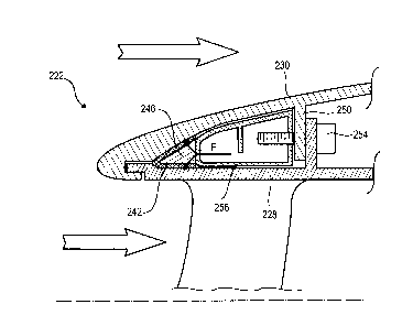
[0065] Figure 5 shows a splitter lip 222 according to the third embodiment of
the
disclosure. This figure 5 repeats the numbering of the preceding figures for
identical or similar elements, this numbering being however increased by
200. Specific numbers are used for the elements specific to this
embodiment. The splitter wall 230 and the outer shroud may be generally
identical to the preceding embodiments.
[0066] The heating means 242 may be identical to those described for figure 4.
The elastic element 246 forms a strip inserted into the heating means 242.
The splitter lip 222 comprises a wedge 256 positioned against the elastic
element 246 and a downstream support, in this case the flange 250 of the
splitter wall 230. The wedge 256 forms an annular spacer which provides
a closer bearing surface. The thrust means 254 may engage with the
wedge 256 and remain remote from the elastic element 246. This lightens
the lip 222.
[0067] During assembly of the splitter lip 222, the elastic element 246 is
placed
on the inside of the heating means 242. Then, the wedge 256 may be
clamped against the elastic element 246 in order to compress the latter
such that it exerts a clamping force F against the heating means. These
then fit tightly against the splitter wall 230 or any other portion which they
can de-ice. Then, the thrust means 254 may be adjusted in order to
modulate the compression of the elastic element 246, and thus the effect
of clamping the heating means 242 on the splitter wall 230.