Note: Descriptions are shown in the official language in which they were submitted.
CONSTANT-CURRENT CONTROLLER FOR AN INDUCTIVE LOAD
CROSS REFERENCE TO RELATED APPLICATIONS
This application claims the benefit of U.S. Patent Application No. 62/147,478,
filed April 14, 2015.
TECHNICAL FIELD
The present invention relates to a constant-current controller for an
inductive
load. More specifically, the invention relates to a constant-current
controller that
produces constant current via switches controlled by pulse-width modulation.
Still more
specifically, the invention relates to a constant-current controller that may
be used, in
one instance, in an electronically actuated door latch mechanism.
BACKGROUND OF THE INVENTION
Solenoids are often used as the driver to operate many types of
electromechanical devices, such as for example electromechanical door latches
or
strikes. In the case of door latches, electromagnetic devices may also be used
as
drivers. In the use of solenoids as drivers in electromechanical door latches
or strikes,
the solenoids may be spring-biased to either a default locked or unlocked
state,
depending on the intended application of the strike or latch. When power is
applied to
the solenoid, the solenoid is powered away from the default state to bias a
return spring.
The solenoid will maintain the bias as long as power is supplied to the
solenoid. Once
power has been intentionally removed, or otherwise, such as through a power
outage
from the grid or as a result of a fire, the solenoid returns to its default
locked or unlocked
state.
In a fail-safe lock system, power is supplied to the solenoid to lock the
latch or
strike. With power removed, a return spring moves the mechanism to an unlocked
1
Date Recue/Date Received 2021-09-08
state. Thus, as long as the latch or strike remains locked, power has to be
supplied to
the solenoid to maintain stored energy in the return spring.
The current to pull in the plunger of the solenoid is referred to as the
"pick"
current and the current to hold the plunger in its activated position is
referred to as the
"hold" current. Typically, the pick current is much greater than the hold
current.
In a fail-secure system, the reverse is true. With power removed, the return
spring moves the latching mechanism to a locked state. Thus, as long as the
latch
remains unlocked, power has to be supplied to the solenoid to maintain stored
energy in
the return spring. Again, the hold current is typically much less than the
pick current.
A system designed to overcome the shortcomings of solenoid lock systems is
disclosed in the prior art disclosure from Sargent Manufacturing Company
(W02014/028332 ¨ herein referred to as "the '332 publication"). As disclosed
in the
'332 publication, the solenoid used to drive the door latch mechanism is
replaced by a
small DC motor that moves a latching plate. This change, in combination with
the motor
aligning with and engaging an auger/spring arrangement, reduced standby
current
consumption of the driver from about 0.5 A to about 15 mA.
U.S. Patent No. 9,183,976, filed March 15, 2013, and assigned to Hanchett
Entry
Systems, Inc. discloses a springless electromagnet actuator having a mode-
selectable
magnetic armature that may be used in door latching applications. A standard
solenoid
body and coils are combined with a non-magnetic armature tube containing a
permanent magnet, preferably neodymium. The magnet is located in one of three
positions within the armature. When biased toward the stop end of the
solenoid, it may
be configured to act as a push solenoid. When biased toward the collar end of
the
solenoid, it may be configured to act as a pull solenoid. In either case, no
spring is
required to return the armature to its de-energized position. Positioning the
magnet in
the middle of the armature defines a dual-latching solenoid requiring no power
to hold it
in a given state. In one aspect, a positive coil pulse moves the armature
toward the stop
end, whereas a negative coil pulse moves the armature toward the collar end.
The
2
Date Recue/Date Received 2021-09-08
armature will remain at the end to which it was directed until another pulse
of opposite
polarity is supplied to the actuator.
Irrespective of the type of electromagnetic actuator used, power to the
inductive
load of an electric latch or strike (such as a solenoid, DC motor, or magnetic
actuator) is
most efficiently maintained if a constant current is provided to the inductive
load.
Therefore, there exists a need for a constant-current controller operable to
supply a
constant current to the inductive load. The present invention fills this need
and other
needs.
SUMMARY OF THE INVENTION
What is presented is a constant-current controller that supplies a constant
current
to an inductive load. The inductive load is composed of an inductance (L) and
series
resistance (R). The controller comprises a switching circuit. The switching
circuit
comprises a primary switch and a secondary switch. During a time interval in
which the
primary switch is closed (ton), the secondary switch is open and the voltage
across the
inductive load is equal to the source voltage (Vs). At time ton until the end
of a time
period (T), with the primary switch open and the secondary switch closed, zero
volts
appears across the inductive load. During this interval, load current
continues to flow
due to the stored energy in the inductance. The periodic current in the
inductive load is
dependent upon the stored energy, the parameters of the control circuit, and
the
duration of ton.
In certain embodiments, the controller further operates as a pulse-width
modulation (PWM) controller that causes the periodic current in the inductive
load to
become constant by implementing a sufficiently large switching frequency. As
the
frequency increases, the boundary current and the peak current approach the
same
constant value. In certain embodiments of this controller, the inductive load
can be a
solenoid, DC motor, or a magnetic actuator. In certain embodiments of this
controller,
the primary switch is a MOSFET and said secondary switch is a free-wheeling
diode.
3
Date Recue/Date Received 2021-09-08
Although not a requirement, the inductive load can be used to lock or unlock
an
electromechanical door latch or electromechanical strike.
In one embodiment of this controller, the switching circuit comprises a
current
transformer, bridge rectifier, burden resistor, and low-pass filter. In this
embodiment, the
current transformer has two single-turn primary windings and one secondary
winding.
The first primary winding is connected in series with the primary switch; the
second
primary winding is connected in series with the secondary switch. The primary
windings
are used for sensing the current of the inductive load. The secondary winding
has N-
turns and is directly connected to the AC input of the bridge rectifier. The
burden
resistor is connected directly across the DC output of the bridge rectifier.
The burden
resistor is directly connected to the low-pass filter.
In another embodiment of this controller, the switching circuit comprises a
current
transformer, bridge rectifier, burden resistor, low-pass filter, and a timer
integrated
circuit (TIC). In this embodiment, the current transformer has two single-turn
primary
windings and one secondary winding. The first primary winding is connected in
series
with the primary switch; the second primary winding is connected in series
with the
secondary switch. The primary windings are used for sensing the current of the
inductive load. The secondary winding has N-turns and is directly connected to
the AC
input of the bridge rectifier. The burden resistor is directly connected to
the DC output
of the bridge rectifier. The burden resistor is directly connected to the low-
pass filter.
The TIC establishes the time interval of the periodic current in the inductive
load. To
function in this manner, the TIC receives a signal through an input that
initiates this time
interval.
In another embodiment of this controller, the switching circuit comprises a
current-
sensing circuit and a PWM controller. The primary switch may be a transistor,
such as a
MOSFET; the secondary switch may be a diode or another MOSFET. The current
sensing circuit may be a current-sense resistor with an amplifier, a current-
sensing
integrated circuit, a Hall-effect current sensor, or any other appropriate
current sensing
4
Date Recue/Date Received 2021-09-08
circuit known in the art. The current-sensing circuit feeds a voltage
proportional to load
current to the PWM controller which correspondingly adjusts the duty ratio to
achieve
the desired load current.
In another exemplary circuit implementation of the constant-current
controller, the
PWM controller controls the duty ratio of the primary switch. The PWM
controller may
be a software-programmable device such as a micro-processor or a firmware-
program mable device such as a micro-controller or FPGA. The PWM controller
may
also contain the necessary circuitry to drive the primary switch. The primary
switch may
be a MOSFET or other appropriate switching device. A secondary switch may be a
diode or other appropriate switching device. A current-sensing circuit
provides a voltage
proportional to load current to the PWM controller which adjusts the duty
ratio to
achieve the desired load current. The current-sensing circuit may be a current-
sense
resistor, a current-sense amplifier, a Hall-effect sensor, or other suitable
current sensing
circuit.
In this embodiment, the current-sensing circuit measures the current of
inductive
load when the primary switch is on and the secondary switch is off. When the
primary
switch is off, current continues to flow through the secondary switch during
which the
time current-sensing circuit continues to measure the current of the inductive
load.
In yet another exemplary circuit implementation of the constant-current
controller,
the PWM controller controls the duty ratios of the primary switch and
secondary switch.
The PWM controller may be a software-programmable device such as a micro-
processor or a firmware-programmable device such as a micro-controller or
FPGA. The
PWM controller may also contain the necessary circuitry to drive the primary
switch and
secondary switch. The primary switch may be a MOSFET or other appropriate
switching
device; the secondary switch may also be a MOSFET or other appropriate
switching
device. The current-sensing circuit provides a voltage proportional to load
current to the
PWM controller which adjusts the duty ratio to achieve the desired load
current. The
5
Date Recue/Date Received 2021-09-08
current-sensing circuit may be a current-sense resistor, a current-sense
amplifier, a
Hall-effect sensor, or other suitable current sensing circuit.
In this embodiment, the current-sensing circuit measures the current of the
inductive
load when the primary switch is on and the secondary switch is off. When the
primary
switch is off, the secondary switch is on and current continues to flow
through the
inductive load and the current-sensing circuit. When the secondary switch is
on and the
primary switch is off, the current-sensing circuit continues to measure the
current of the
inductive load. The PWM controller generates the appropriate signals to
synchronously
alternate the on-times and off-times of the primary and secondary switches,
respectively.
What is also presented is a method of providing a constant-current to an
inductive load. This method comprises the steps of sending an electric current
to a
switching circuit; sending the electric current through a primary switch
during a time
interval in which the primary switch is closed (ton) and a secondary switch is
open, which
causes the voltage across the inductive load to be substantially equal to the
source
voltage (Vs); sending the electric current through the secondary switch during
the time
interval in which the secondary switch is closed and the primary switch is
open, which
causes the voltage across the inductive load to fall to 0. At ton until the
end of a time
period (T), zero volts appears across the inductive load. During this
interval, load
current continues to flow due to the stored energy in the inductance. The
periodic
current in the inductive load is dependent upon the stored energy, the
parameters of the
control circuit, and the duration of ton.
In one embodiment of the method, the method further comprises the step of
causing the periodic current in the inductive load to become constant through
the
.. implementation of a sufficiently large switching frequency generated
through pulse-
width modulation (PMW). In certain instances, the boundary current and the
peak
current are forced to substantially the same constant value as the PWM
frequency
increases. In certain embodiments of this method, the inductive load can be a
solenoid,
6
Date Recue/Date Received 2021-09-08
DC motor, or a magnetic actuator. In certain embodiments of this method, the
primary
switch is a MOSFET and said secondary switch is a free-wheeling diode.
Although not a
requirement, the inductive load can be used to lock or unlock an
electromechanical door
latch or electromechanical strike.
BRIEF DESCRIPTION OF THE DRAWINGS
The present invention will now be described, by way of example, with reference
to the accompanying drawings, in which:
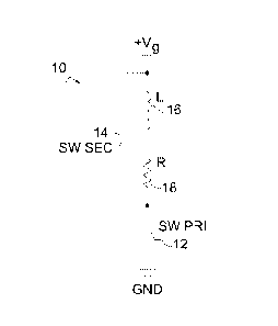
FIG. 1 is a functional schematic of a switching circuit, in accordance with an
aspect of the present invention;
FIG. 2 is a plot of the instantaneous load current for the switching circuit
shown in
FIG. 1 at a switching frequency of 100 Hz;
FIG. 3 is a plot of the instantaneous load current for the switching circuit
shown in
FIG. 1 at a switching frequency of 1,000 Hz;
FIG. 4 is a plot of the instantaneous load current for the switching circuit
shown in
FIG. 1 at a switching frequency of 100,000 Hz;
FIG. 5 is a schematic of an embodiment of a constant current PWM controller
circuit, in accordance with an aspect of the present invention;
FIG. 6 is a schematic of another embodiment of a constant current PWM
controller circuit configured for pick and hold states, in accordance with a
further aspect
of the present invention;
FIG. 7 is a generalized schematic of another embodiment of an asynchronous
constant-current PWM controller in accordance with a further aspect of the
present
invention; and
FIG. 8 is a generalized schematic of another embodiment of a synchronous
constant-current PWM controller in accordance with a further aspect of the
present
invention.
7
Date Recue/Date Received 2021-09-08
Corresponding reference characters indicate corresponding parts throughout the
several views. The exemplifications set out herein illustrate currently
preferred
embodiments of the invention, and such exemplifications are not to be
construed as
limiting the scope of the invention in any manner.
DESCRIPTION OF THE PREFERRED EMBODIMENTS
A functional schematic of the switching circuit 10 that produces constant
current
in an inductive load via switches controlled by pulse-width modulation (PWM)
is shown
in FIG. 1. As shown in the figure, there are two switches; a primary switch 12
and a
secondary switch 14. When primary switch 12 is closed, the secondary switch 14
is
open. When the primary switch 12 is open, the secondary switch 14 is closed.
The
series resistance (R), indicated in the circuit as resistor 18, is the sum of
the coil
resistance and the load resistance. Coil inductance and total circuit
resistance comprise
the inductive load.
In accordance with an aspect of the present invention, when primary switch 12
is
closed, source voltage (Vs) is applied across inductor ("coil") 16 and
resistor 18.
However since coil 16 opposes any change in current flow by producing a
counter
electromotive force (EMF) equal to the source voltage, current flow through
coil 16 and
resistor 18 is zero at the instant the primary switch 12 is closed, i.e.,
(to). Once primary
switch 12 is closed, the counter EMF begins to decay until the voltage across
coil 16
and resistor 18 equals the source voltage Vs, thereby allowing a current to
flow through
coil 16 and resistor 18. The time interval in which primary switch 12 is
closed may be
defined as ton.
At the beginning of the time interval when secondary switch 14 is closed and
primary switch 12 is opened (i.e. from ton until the end of the cycle (T)),
there is no
longer a source voltage Vs across coil 16. Once again, coil 16 opposes the
change in
current flow by producing a positive EMF equal to the source voltage Vs in the
direction
that was the source voltage's direction. Therefore, current continues to flow
through coil
8
Date Recue/Date Received 2021-09-08
16 and resistor 18 without source voltage Vs being applied. From ton to the
end of the
cycle T, current through and voltage across coil 16 and resistor 18 decays to
zero via
the EMF discharged by coil 16. As such, the current in the inductive load is
dependent
upon the circuit parameters and the rate at which the switches 12 and 14 are
opened
.. and closed with respect to each other. This rate is the PWM frequency (f).
From the above discussion, it can be understood that current flow may be held
constant by increasing the frequency in which the switches 12 and 14 are
opened and
closed. If the primary switch 12 is closed before the current decays to zero,
the initial
current becomes the boundary current. The load current is equal to the
boundary
current at the beginning and end of each period T. Non-zero boundary current
increases
the average value of the load current. As the period T is decreased
substantially less
than the L/R time constant, wherein L/R is the ratio of coil inductance to
circuit
resistance, the current may be held to any value between 0 and Vs/R by varying
the
duty ratio of primary switch 12, where the duty ratio is defined by ton IT.
This constant
current control is especially useful since, in the example of a magnetic lock,
power to
the lock can be precisely controlled by varying the duty ratio (i.e., power
can be
increased to resist an instantaneous and unwanted attempt to open the door yet
be
reduced while the door is at idle). That is, for a sufficiently high
frequency, the current is
constant and can be maintained by a PWM controller so as to be any value
between 0
and Vs/R, as will be discussed in more detail below with regard to FIGS. 5 and
6.
From the above description, it should be apparent that there are two switching
intervals defined during one cycle of the PWM frequency. At the beginning of
the cycle,
primary switch 12 is closed (secondary switch 14 is open). During this
interval, the load
current is described by:
t
il(t) = Aie T-F
T=k
9
Date Recue/Date Received 2021-09-08
where T (tau) is the circuit's time constant, L is the inductance of coil 16
and R is the
series resistance.
Before the end of the cycle T, primary switch 12 is opened and secondary
switch
14 is closed. As recounted above, this switching instant defines ton which
represents the
time during which the primary switch is closed. The ratio of ton to the PWM
switching
period is defined as the duty ratio:
ton
D =
T
After ton (i.e. when secondary switch 14 is closed) the secondary switch
becomes
a short circuit across the inductive load. During the interval from ton to T,
the load current
is described by
t
12(0 = A2e T
The complete definition of the load current is thus described by two current
components defined over their respective time intervals:
t
V
LOAD li 10( = A te T + 2, 0 < t < ton
1
t
i2(t), A2e T , R ton < t < T
Constants Ai and A2 are determined from the boundary conditions.
Boundary Conditions
Since the load current is periodic, the two current components are equal at
the
beginning and at the end of the cycle:
i1(0) = i2(T)
Substitution of this boundary condition into the load current definition
yields:
T
V s
Ai+ T= Aze T
(1)
The two currents are also equal at ton because inductor current cannot change
instantaneously:
Date Recue/Date Received 2021-09-08
qt.) = i2(t0n)
Substitution of this boundary condition yields:
ton
on v
Ale T ¨R = A e
(2)
The solution of Equations (1) and (2) for the constants is
Vs 1_ e- T(1- D)h-
=
R 1_ e-TIT
Vs[1¨eDTIT1
A2=
R 1¨ e-TITi
A plot of the instantaneous load current during one PWM cycle is shown in
Figure 2 where Vs = 25, L = 220 mH, R = 50 0, f = 100 Hz, and D = 0.5. As can
be
seen in FIG. 2, the load current has the exponential forms characteristic of a
first-order
circuit. In this case, the circuit is composed of two sub-circuits; the first
is supplied by a
DC source while the second is source-free. Thus, the switching elements create
a
system of variable structure with a periodic current response. As outlined
below, this
periodic current may be made constant through the implementation of a
sufficiently
large PWM switching frequency.
Constant Current Control
The peak current is obtained upon substitution of t = ton = DT in either
current
component:
vsr - e-DT/T1
k ¨
P R 1¨ e-irl'T
The current at the beginning of the cycle is obtained upon substitution of t =
0 in the first
component:
vs e- T(1- DVE e-Tti
1¨ e-TIT
The same value is obtained upon substitution of t = T in the second current
component:
11
Date Recue/Date Received 2021-09-08
Vs e-T(1-D)IT _e-TIT
i2(nl= R ___________________________________________
1¨ e-TIT
As the PWM frequency increases, the PWM period decreases. Specifically, as f
approaches infinity, T approaches zero. As T 0, the peak current becomes:
vs[t - e-DT/TI DV,
R[1¨ e _______________________________________ TIT T->0 R
The boundary currents become:
Vs e- T(1 -D)IT _e-DTIT DVs
1¨ e-
Thus, the boundary current and the peak current approach the same constant
value as
the PWM frequency increases. Consequently, for a sufficiently high frequency,
the load
current is essentially constant and is dependent only on the source voltage
Vs, series
resistance R, and the duty ratio D:
DV,
iLOAD-
A sufficiently high switching rate is one for which the switching period T is
much less
than the circuit time constant
TT
Conclusion
For high switching rates, the load current varies between 0 and Vs/R as the
duty
ratio varies between 0 and 100%:
vs
0 < fLOAD <
O<D <
By way of example, FIGS. 3 and 4 show load currents for switching rates of 1
kHz and
100 kHz, respectively.
12
Date Recue/Date Received 2021-09-08
Access Control Systems
One example of utilizing the above constant-current controller is within the
field of
access controls. For instance, it has been found that power to a latch having
an
inductive load actuator, such as but not necessarily limited to either a
magnetic lock or a
solenoid, is most efficiently provided if a constant current is provided to
the latch. An
exemplary circuit 20 for a constant-current PWM controller 22 is show in FIG.
5. The
circuit makes use of a PWM controller integrated circuit 22 with current
sensing used as
the feedback mechanism. The primary switch 24 is typically a MOSFET (analogous
to
primary switch 12 described above) while the secondary switch 26 (i.e. switch
14) is
typically a free-wheeling diode (shown as "Dfw"). It should be understood by
those
skilled in the art that any suitable switching device may be used in place of
MOSFET 24
and diode 26 and that such alternative switches are to be considered within
the scope
of the present invention.
A current transformer 28 with two single-turn primary windings 30a and 30b and
one secondary winding 32 with N-turns is used to sense the two components of
the load
current 34a and 34b. Primary windings 30a and 30b are connected in series with
switches 24 and 26, respectively. Secondary winding 32 is connected to a
bridge
rectifier 36, burden resistor (RB) 38, and low-pass filter resistor (Rf) 40
and capacitor (Cf)
42. It should be noted that any component having an equivalent functionality
to the
current transformer 28 may be installed within circuit 20. For example, a
skilled artisan
will see that the current transformer 28 may be replaced with Hall-effect
sensors
specified to have similar functionality.
When MOSFET 24 (i.e. primary switch 12) is on, the first current component
flows through the primary winding at Terminals 3 and 4. This component is
transformed
to the secondary winding 32 as:
DV,
is ¨ NR,0 < t < to,
When MOSFET 24 turns off, the coil current continues to flow, due to the
stored
energy, but is now diverted into the free-wheeling diode 26 (i.e. secondary
switch 14).
13
Date Recue/Date Received 2021-09-08
This second current component now flows through the primary winding at
Terminals 1
and 2. Due to the arranged phasing of the current transformer 28, the second
current
component is transformed to the secondary winding 32 as:
DV,
NR'tmiT
The secondary currents are rectified through bridge rectifier 36 to produce a
constant
current through the burden resistor 38:
DVs
iR¨ ______________________________________ 0 <t <7'
NR' ¨ ¨
The value of the burden resistor is calculated to produce a voltage that is
equal to the
internal voltage reference, Vr, of the integrated circuit:
NR'
J,R= __________________________________________
D
Thus, the value of burden resistance 38 establishes the feedback voltage to
the
PWM controller 22 at Vr. At this voltage, PWM controller 22 regulates the
current
through the inductive load to maintain the feedback voltage at this operating
point.
Thus, the value of RB establishes the value of the constant current through
the inductive
load.
FIG. 6 shows another exemplary circuit schematic 50 that may be suitable for
use in a latching system which employs a solenoid. As is recognized in the
art,
solenoid-driven actuators have long been known for their power inefficiencies.
It is
further known that their pull-in current (pick current) is higher than the
current needed to
hold the solenoid plunger in place (hold current). Therefore, to save energy,
it is
desirable for the controller to step down the current after the fixed duration
of time
during which the pick current has been applied. Furthermore, in a Fail-Secure
system,
the solenoid is often under full-power mode as long as the door needs to
remain
unlocked. Conversely, in a Fail-Safe system, the solenoid is in full-power
mode as long
as the door needs to remain locked. Thus, without further control, a
significant amount
of power is wasted while the solenoid remains powered.
14
Date Recue/Date Received 2021-09-08
To improve energy efficiencies, circuit 50 may use a combination of individual
resistors in parallel to produce a collective burden resistor that may be used
to change
the operating current in the inductive load. In the case of a solenoid, two
operating
points are required, with the first being the pull-in or pick current. This
relatively large
current is sourced into the solenoid coil for a short time interval to engage
the solenoid.
Once the solenoid has been actuated, the pick current is followed by a much
smaller
holding or hold current to maintain the position of the solenoid plunger. In
accordance
with an aspect of the present invention, this pick and hold operation may be
accomplished using a constant current controller by changing the value of the
burden
resistor once the solenoid has engaged, as will be discussed in greater detail
below.
Circuit 50 makes use of a timer integrated circuit 52 to establish the time
interval
of the pull-in operation. The timer receives a signal through input 54 that
initiates the
pull-in interval. With no signal applied, transistor 56 (Q7) is on, Pin 1
(58a) of PWM
controller 58 (U14) is pulled to ground such that PWM controller 58 is
disabled. As a
result, no current flows through the solenoid coil connected at terminals 34a
(+24VDC)
and 34b (OUT#2).
When input 54 is switched to logic-level HIGH, PWM controller 58 is enabled
and
the pick interval starts with a logic-level HIGH at the OUT pin (52a) of timer
integrated
circuit 52. This output turns on transistor 60 (Q8) and connects resistor 62
(R71) and
resistor 64 (R72) in parallel. This combined resistance value establishes the
value of the
pull-in current. Once the pull-in interval has expired, OUT pin 52a returns to
a logic-
level LOW, transistor 60 (Q8) turns off, and resistor 62 (R71) is disconnected
from the
circuit. Resistor 64 (R72) remains as the burden resistance and establishes
the hold
current of the solenoid. By way of example, if resistor 62 has a resistance of
100 ohms
and resistor 64 has a resistance of 10,000 ohms and 24 V is being supplied,
the pick
current will be about 0.24 A (24 V/99 ohms = 0.24 A) while the hold current
will be about
2.4 mA (24 V/10,000 ohms = 0.0024 A). In this manner, power efficiencies may
be
Date Recue/Date Received 2021-09-08
realized as high current is applied only for a set, limited period of time
before the circuit
switches to provide the less-demanding hold current.
It should be understood by those skilled in the art that the concept of
multiple
operating points with respective time intervals may be extended by the
addition of any
number of switched burden resistors with timing circuits. Such concepts are
included
within the present disclosure.
Another exemplary circuit implementation 70 of the constant-current controller
is
shown in FIG. 7. In this schematic, PWM controller 72 controls the duty ratio
of primary
switch 78. PWM controller 72 may be a software-programmable device such as a
micro-
processor or a firmware-programmable device such as a micro-controller or
FPGA.
PWM controller may also contain the necessary circuitry to drive primary
switch 78.
Primary switch 78 may be a MOSFET or other appropriate switching device;
secondary
switch 80 may be a diode or other appropriate switching device. Current-
sensing circuit
74 provides a voltage proportional to load current to the PWM controller which
adjusts
the duty ratio to achieve the desired load current. The current-sensing
circuit may be a
current-sense resistor, a current-sense amplifier, a Hall-effect sensor, or
other suitable
current sensing circuit.
Current-sensing circuit 74 measures the current of inductive load 76 when
primary switch 78 is on and secondary switch 80 is off. When primary switch 78
is off,
current continues to flow through secondary switch 80 during which time
current-
sensing circuit 74 continues to measure the current of inductive load 76.
A final exemplary circuit implementation 90 of the constant-current controller
is
shown in FIG. 8. In this schematic, PWM controller 92 controls the duty ratios
of primary
switch 98 and secondary switch 100. PWM controller 92 may be a software-
programmable device such as a micro-processor or a firmware-programmable
device
such as a micro-controller or FPGA. PWM controller 92 may also contain the
necessary
circuitry to drive primary switch 98 and secondary switch 100. Primary switch
98 may be
a MOSFET or other appropriate switching device; secondary switch 100 may be a
16
Date Recue/Date Received 2021-09-08
MOSFET or other appropriate switching device. Current-sensing circuit 94
provides a
voltage proportional to load current to the PWM controller which adjusts the
duty ratio to
achieve the desired load current. The current-sensing circuit may be a current-
sense
resistor, a current-sense amplifier, a Hall-effect sensor, or other suitable
current sensing
.. circuit.
Current-sensing circuit 94 measures the current of inductive load 96 when
primary
switch 98 is on and secondary switch 100 is off. When primary switch 98 is
off,
secondary switch 100 is on and current continues to flow through inductive
load 96 and
current-sensing circuit 94. When secondary switch 100 is on and primary switch
98 is
off, current-sensing circuit 94 continues to measure the current of inductive
load 96.
PWM controller 92 generates the appropriate signals to synchronously alternate
the on-
times and off-times of primary and secondary switches 98 and 100,
respectively.
While the invention has been described by reference to various specific
embodiments, it should be understood that numerous changes may be made within
the
spirit and scope of the inventive concepts described. Accordingly, it is
intended that the
invention not be limited to the described embodiments, but will have full
scope defined
by the language of the following claims.
17
Date Recue/Date Received 2021-09-08