Note: Descriptions are shown in the official language in which they were submitted.
SYSTEM AND METHOD FOR FORMING METAL CONTAINER WITH EMBOSSING
[0001] Continue to next paragraph.
BACKGROUND OF THE INVENTION
[0002] The present invention relates generally to the field of metal
containers. The present
invention relates specifically to metal containers having sunken or raised
embossing, such as an
embossed logo, and tools configured to form such embossing.
SUMMARY OF THE INVENTION
[0003] One embodiment of the invention relates to a system for formation of
embossed indicia on
the end wall of a metal food can. The system includes a first die portion
having an outer surface and a
second die portion having an outer surface. The second die portion opposes the
first die portion, and
the outer surface of the first die portion and the outer surface of the second
die portion are configured
to form the end wall of the metal food can. The system includes a first
fastener formed from a metal
material coupled to the first die portion. The first fastener includes an
outer surface and a raised profile
extending from the outer surface corresponding to the embossed indicia to be
formed on the wall of the
metal food can. The system includes a second fastener formed from a metal
material coupled to the
second die portion. The second fastener includes a head portion including an
inner surface and a recess
formed in the head portion defined by the inner surface of the head portion.
The system includes a pad
of polymeric material positioned within the recess and coupled to the inner
surface of the head portion.
The pad has an axially facing outer surface facing the raised profile of the
first fastener. The system
includes an actuator coupled to at least one of the first fastener and the
- 1 -
CA 2927453 2019-05-07
CA 02927453 2016-04-13
WO 2015/057249 PCT/US2013/075445
second fastener and configured to move the first fastener and the first die
portion toward the
second fastener and the second die portion such that the outer surface of the
first die portion and
the raised portion of the first fastener engage a first surface of the end
wall and that the outer
surface of the second die portion and the pad of the second fastener engage a
second surface of
the end wall. The first fastener couples the first die section to one of the
actuator or a die base,
and the second faster couples the second die section to other of the actuator
or the die base.
[0004] Another embodiment of the invention relates to tool for embossing
indicia on a wall
of a metal container. The tool includes a shaft having a longitudinal axis, a
first end and a
second end. The tool includes a head portion coupled to the first end of the
shaft. The head
portion includes a lower axially outward facing surface and an inner sidewall
surface extending
substantially perpendicular to and away from the lower axially outward facing
surface such that
the lower axially outward facing surface and the inner sidewall surface define
a recess. The head
portion includes an outer sidewall surface defining the outer perimeter of the
head portion and an
upper axially outward facing surface extending between the inner sidewall
surface and the outer
sidewall surface. The tool includes a pad of polymeric material positioned
within the recess and
coupled to the head portion.
[0005] Another embodiment of the invention relates to a method of forming
embossed
indicia on a wall of a metal food can. The method comprises providing a first
tool coupled to a
first die portion, and the die portion includes an outer surface and a raised
profile extending from
the outer surface corresponding to the embossed indicia to be formed on the
wall of the metal
food can. The method includes providing a second tool coupled to a second die
portion, the
second tool including a recess and a pad of polymeric material positioned
within the recess. The
pad has an axially facing outer surface facing the raised profile of the first
tool. The method
includes positioning a wall of a metal food can between the raised profile of
the first tool and the
pad of the second tool. The method includes engaging a first surface of the
wall of the metal
food can with the raised profile of the first tool and engaging a second
surface of the wall of the
metal food can with the pad of the second tool. The method includes applying
pressure to the
wall of the metal food can between the first and second tools causing the
deformation of the wall
of the metal food can to conform to the shape of the raised profile to form
the indicia.
-2-
CA 02927453 2016-04-13
WO 2015/057249 PCT/US2013/075445
[0006] Alternative exemplary embodiments relate to other features and
combinations of
features as may be generally recited in the claims.
BRIEF DESCRIPTION OF THE DRAWINGS
[0007] This application will become more fully understood from the
following detailed
description, taken in conjunction with the accompanying figures, wherein like
reference
numerals refer to like elements in which:
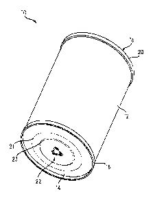
[0008] FIG. 1 is a perspective view of a can having an embossed area
according to an
exemplary embodiment.
[0009] FIG. 2 is a bottom view of the can of FIG. 1 according to an
exemplary embodiment.
[0010] FIG. 3 is a cross-sectional view taken through the embossed area of
the can of FIG. 1.
[0011] FIG. 4 is a first embossing tool according to an exemplary
embodiment.
[0012] FIG. 5 is a second embossing tool according to an exemplary
embodiment.
[0013] FIG. 6 is a sectional view of the second embossing tool of FIG. 5.
[0014] FIG. 7 is an enlarged detail view of a portion of the second
embossing tool shown in
FIG. 6.
[0015] FIG. 8 is a second enlarged detail view of a portion of the second
embossing tool
shown in FIG. 6.
[0016] FIGS. 9A - 9C show operation of an embossing system according to an
exemplary
embodiment.
[0017] FIG. 10 is a flow-diagram showing a method of embossing a metal
container
according to an exemplary embodiment.
DETAILED DESCRIPTION
[0018] Referring generally to the figures, various embodiments of a system
and method for
forming a metal container, such as a metal food can, that includes an embossed
area, such as an
embossed pattern or logo, are shown and described. In contrast to some surface
pattern or logo
formation techniques, such as incising, the system and method described herein
forms a raised or
sunken design in the metal surface of the metal container by alteration of the
shape of the piece
-3-
CA 02927453 2016-04-13
WO 2015/057249 PCT/US2013/075445
of material typically without substantial removal of material. As used herein,
embossing
includes both raised and sunken indicia formed in the metal container.
Further, the embossing
system and method is configured to create embossing even on the relatively
thin metal (e.g.,
steel, aluminum, tinplate, etc.) that forms the sidewalls and/or end walls of
commercial metal
food containers.
[0019] In general, the system for forming an embossed pattern or logo
includes a pair of
opposing embossing tools. The first tool includes a raised profile in the
shape of the pattern or
logo to be formed and is formed from a strong rigid material (e.g., steel).
The second tool
includes a recess defined by a wall of strong rigid material and a pad of a
softer or compliant
material (e.g., a rubber or plastic material) positioned in the recess.
[0020] The portion of the container to be embossed (e.g., a can sidewall, a
can end wall, etc.)
is positioned between the first tool and the second tool, and the raised
profile of the first tool is
aligned with the compliant pad of the second tool. The first tool and the
second tool are moved
toward each other to engage a portion of the container between the tools. The
raised profile of
the first tool engages the portion of the container deforming it to adopt the
shape of the raised
profile, and at the same time, the pad of softer material engages the opposite
side of the portion
of the container. As the material of the container is deformed, the softer
material of the pad
compresses under the force of the embossing tool. Thus, the pad acts to
support the portion of
the container being deformed, and thereby facilitates formation of the
embossing while limiting
the potential of damage (e.g., cracking) of the material of the container.
Further, various
embodiments of the second tool discussed herein provide a tool that is robust
providing extended
tool life and wear resistance at speeds typical of commercial metal food can
production
equipment.
[0021] In various embodiments, both the upper and lower tool are fasteners,
e.g., bolts, that
hold together die sections configured to shape a portion of a metal food
container. In one such
embodiment, the die sections are configured to form contours or beads into a
can end or into the
integral end wall of a two piece can. In another such embodiment, the die
sections are
configured to form the body of a two piece can. In such embodiments, the upper
and lower tools
act both as embossing tools and as fasteners that hold together the
respective, opposing die
components. In these embodiments, by integrating the embossing tools into the
fasteners that
-4-
CA 02927453 2016-04-13
WO 2015/057249 PCT/US2013/075445
hold together components of the die, embossing is provided in synchronism with
the formation
of the can or can component by reducing the need for excess tooling and for a
separate
embossing step in the can manufacturing process.
[0022] Referring to FIG. 1, a metal container, shown as can 10, is shown
according to an
exemplary embodiment. Can 10 includes a sidewall 12, a first end wall, shown
as bottom end
wall 14 and a second end wall, shown as top end wall 16. Bottom end wall 14 is
coupled to a
first or lower end of sidewall 12, and top end wall 16 is coupled to a second
or upper end of
sidewall 12. In the embodiment shown, can 10 is a metal food can, and sidewall
12, bottom end
wall 14, and top end wall 16 are formed from metal, specifically steel or
aluminum. In this
embodiment, bottom end wall 14 is coupled to sidewall 12 via a seam, shown as
lower double
seam 18, and top end wall 16 is coupled to sidewall 12 via a seam, shown as
upper double seam
20. In various embodiments, double seams 18 and 20 are hermetic double seams
formed from
interlocked and crimped together portions of the end walls and the lower and
upper ends of
sidewall 12, respectively. In other embodiments, can 10 is a two piece can and
one of the end
walls, 14 or 16, is integral with sidewall 12.
[0023] In various embodiments, can 10 is substantially cylindrical can
having a substantially
cylindrical sidewall 12. In other embodiments, can 10 is a non-cylindrical can
having a non-
cylindrical sidewall 12. In various embodiments, can 10 is a metal food can
configured to
hermetically hold a food product within the can.
[0024] Can 10 includes an embossed area, shown as embossed logo 22, formed
in bottom
end wall 14. Embossed logo 22 is shown in FIG. 1 as the recycle logo. However,
embossed
logo 22 may be any logo, indicia, pattern, etc. that that can be formed via
embossing in a metal
material, and specifically a metal packaging material. In the embodiment
shown, lower end wall
14 includes one or more concentric steps, shown as panel steps 21 and 23, and
in one
embodiment, embossed logo 22 is located in the center of steps 21 and 23.
Further, embossed
logo 22 can be formed in any portion of can 10 including sidewall 12 or top
end wall 16.
[0025] Referring to FIG. 2 a plan view of lower end wall 14 is shown
according to an
exemplary embodiment. As shown logo 22 is located in the center of lower end
wall 14. As
shown best in FIG. 3, logo 22 is an embossed logo formed from outwardly
deformed sections of
end wall 14 in the shape of logo 22. Specifically, lower end wall 14 includes
an inner surface 30
-5-
CA 02927453 2016-04-13
WO 2015/057249 PCT/US2013/075445
and an outer surface 32. Logo 22 is formed by a deformation of the material of
end wall 14 such
that both inner surface 30 and outer surface 32 at the position of logo 22
deflects outward or
inward while the thickness of the material of end wall 14 that forms at least
the majority of logo
22 is substantially the same as the thickness at the non-embossed areas.
[0026] Logo 22 formed by the deformation of material as shown in FIG. 3 may
provide a
crisp and easy to view logo. In particular in some embodiments, the embossed
logo 22 provides
better viewability than logos formed by incising processes. Further, in
contrast to an incising
process, the thickness of end wall 14 remains substantially constant through
the majority of the
embossed and non-embossed areas such that logo 22 does not result in a
substantially thinned or
weakened portion of end wall 14. In some such embodiments, logo 22 may result
in localized
thinning as part of the embossing process, particularly at high radius areas
such as the arrow
heads of the recycle logo. While logo 22 is shown as an outwardly projecting
or raised
embossed logo, in other embodiments, logo 22 can be a sunken logo such that
both inner surface
30 and outer surface 32 at the position of logo 22 deflects inward toward the
interior of can 10.
[0027] Referring to FIG. 4 and FIG. 5, a first tool, shown as upper tool
40, and a second tool,
shown as lower tool 42, are shown according to exemplary embodiments. Upper
tool 40
includes a raised profile 44 that is shaped in the pattern or design of
embossed logo 22. In the
embodiment shown in FIG. 4, upper tool 40 includes a head portion 46 and a
shaft 48. Head
portion 46 has a width (e.g., dimension perpendicular to the longitudinal axis
of upper tool 40)
greater than the width of shaft 48. Shaft 48 includes threads 50, and threads
50 are used to
couple upper tool 40 to the machine used during embossing. In one embodiment,
discussed in
more detail below, the threads of upper tool 40 are threaded into a die, and
upper tool 40 acts as a
fastener that holds together the die. In one such embodiment, upper tool 40 is
a bolt that holds
together the upper portion of a die that forms panel steps 21 and 23 into end
wall 14. In another
embodiment, upper tool 40 is a bolt that holds together the upper portion of a
die that forms an
integral sidewall and end wall of a two piece can.
[0028] Head portion 46 includes a peripheral edge 52 and an outer surface,
shown as upper
surface 54, surrounded by peripheral edge 52. Upper surface 54 is
substantially perpendicular to
the longitudinal axis of upper tool 40 and faces away from shaft 48. Surface
54 is a substantially
planar surface extending between opposing sections of peripheral edge 52.
Raised profile 44 is a
-6-
CA 02927453 2016-04-13
WO 2015/057249 PCT/US2013/075445
shaped section that extends outward from surface 54 such that the outermost
surface of raised
profile 44 is above surface 54 (in the orientation of FIG. 4). Shaft 48
extends from the side of
head portion 46 opposite of surface 54. Head portion 46 has a sidewall 56 that
extends
downward and away from surface 54 at peripheral edge 52. In the embodiment
shown in FIG. 4,
head portion 46 is hexagonally shaped such that sidewall 56 has six faces 58.
[0029] In various embodiments, raised profile 44 extends above upper
surface 54 a sufficient
distance to form embossing within the relatively thin metal typical of metal
food containers. In
one embodiment, the height of raised profile above upper surface 54 is between
0.005 inches and
0.02 inches, specifically is between 0.005 inches and 0.015 inches, and more
specifically is
between 0.008 inches and 0.012 inches.
[0030] Referring to FIG. 5, lower tool 42 includes a head portion 60 and a
shaft 62. Head
portion 60 has width greater than the width of shaft 62. Shaft 62 includes
threads 64, and threads
64 are used to couple lower tool 42 to the machine used during embossing. In
one embodiment,
discussed in more detail below, the threads of lower tool 42 are threaded into
a die, and lower
tool 42 acts as a fastener that holds together the die. In one such
embodiment, lower tool 42 is a
bolt that holds together the lower portion of a die that forms panel steps 21
and 23 into end wall
14. In another embodiment, lower tool 42 is a bolt that holds together the
lower portion of a die
that forms an integral sidewall and end wall of a two piece can.
[0031] Head portion 60 includes a peripheral edge 66 defining the outer
perimeter of head
portion 60. Head portion 60 has a sidewall 68. Sidewall 68 has an outer
sidewall surface, shown
as planar faces 70. In the embodiment shown, sidewall 68 is a continuous
sidewall that extends
completely around head portion 60 such that planar faces 70 face radially
outward and define the
outer surface or perimeter of head portion 60. In the embodiment shown in FIG.
5, head portion
60 is hexagonally shaped such that sidewall 68 has six faces 70.
[0032] Head portion 60 of lower tool 42 includes a recess 72 defined by an
inner sidewall
surface, shown as inner surface 74, of sidewall 68 and by a lower axially
outward facing surface,
shown as lower recess surface 76. Surface 76 is the upper most surface of a
disc shaped bottom
wall portion of head 60. Surface 76 defines the bottom surface of recess 72,
and surface 74
defines that lateral surface of recess 72. In the embodiment shown, surface 74
is substantially
perpendicular to surface 76 such that recess 72 is a substantially cylindrical
void. However, in
-7-
CA 02927453 2016-04-13
WO 2015/057249 PCT/US2013/075445
other embodiments, surface 74 and/or surface 76 are positioned and shaped to
form voids of
other shapes, e.g., cube-shaped, rectangular prism, pyramidal, etc. It should
be understood that
as used herein the term radial generally relates to a direction perpendicular
to the longitudinal
axes of the tools discussed herein. It should be further understood that
positional terms, such as
radial or circumferential, relate to positional relationships and do not
necessarily require a
circular, spherical or cylindrical shaped feature,
[0033] Lower tool 42 includes a disc or pad, shown as disc 80, located
within recess 72.
Disc 80 is made from a compliant material that acts to support the portion of
the container being
embossed and thereby facilitates formation of the embossing while limiting the
potential of
damage (e.g., cracking) to the material of the can. In one embodiment, disc 80
is coupled within
recess 72 via an adhesive material. In the embodiment shown, a lower surface
of disc 80 is
coupled to surface 76 via the adhesive, and a portion of the cylindrical,
radially outward facing,
outer surface 84 of disc 80 is coupled to inner surface 76 of head portion 60
via the adhesive. In
various embodiments, disc 80 is a polyurethane material and the adhesive is a
polyurethane
compatible adhesive. In one embodiment, the adhesive that couples disc 80
within recess 72 is
the Chemlok 218 Adhesive available from LORD Corporation.
[0034] In various embodiments, the structure and arrangement of disc 80
within recess 72
acts to facilitate embossing of the thin metal typical in food packaging while
also providing a
tool that can withstand the rigors of a high throughput can manufacturing
process. In various
embodiments, the material of disc 80 is selected to provide sufficient wear
resistance (e.g.,
provide an average tool life of at least 30 days) while remaining resilient
(e.g., to spring back to
non-compressed position as shown in FIG. 6). In various embodiments, disc 80
is formed from a
polymer material, and in a specific embodiment, disc 80 is formed from a
polyurethane material.
In various embodiments, disc 80 is formed from a material having an A scale
durometer of
between 80 and 98, and more specifically between 90 and 95. In a specific
embodiment, disc 80
is formed from a polyurethane material with an A scale durometer of 95.
[0035] In addition to the material of disc 80, the geometry of lower tool
42 is selected to
provide increased wear resistance. In various embodiments, disc 80 is shaped
such that the
width of an upper portion 82 of disc 80 decreases as the distance from lower
recess surface 76
increases defining an angled, radially outward facing surface, shown as angled
outer surface 88.
-8-
CA 02927453 2016-04-13
WO 2015/057249 PCT/US2013/075445
The radially inward taper of upper portion 82 of disc 80 results in a gap 86.
Gap 86 is the space
or void formed between the outer surface 88 of upper tapered portion 82 and
the upper portion of
sidewall surface 74. Gap 86 allows sufficient room for disc 80 to deform
during embossing
without causing excessive wear that may otherwise be caused by contact between
disc 80 and
sidewall 68 during embossing.
[0036] As shown in FIG. 7, disc 80 includes an upper surface, shown as
axial facing
uppermost surface 90. In various embodiments, recess 72 has a width, shown as
diameter D1,
and the uppermost surface 90 of disc 80 has a width, shown as diameter D2. In
various
embodiments, D2 is less than D1 such that gap 86 has a width D3 (measured
between the inner
diameter of inner surface 74 and outer diameter of shoulder 108) . In various
embodiments, D1
is between 0.5 inches and 1 inch, specifically between 0.6 inches and 0.9
inches, and more
specifically between 0.8 inches and 0.9 inches. In various embodiments, D2 is
between 0.4
inches and 1 inch, specifically between 0.5 inches and 0.8 inches, and more
specifically between
0.65 inches and 0.75 inches. In various embodiments, D3 is between 0.01 inches
and 0.05 inches
and more specifically is between 0.02 inches and 0.03 inches. In one
embodiment, D1 is 0.750
inches, D2 is 0.7 inches and D3 is 0.025 inches. Head portion 60 has a width,
shown as outer
diameter D4. In various embodiments, D4 is between 0.5 inches and 1.5 inches,
specifically
between 0.9 inches and 1.1 inches, and more specifically between 0.95 inches
and 1.05 inches.
In a specific embodiment, D4 is 1.032 inches.
[0037] Sidewall 68 of lower tool head portion 60 has an upper axially
outward facing
surface, shown as uppermost surface 92, an angled surface 94 and an outer
sidewall surface,
shown as surface 96 that defines faces 70. Uppermost surface 92 is a
substantially horizontal
surface surrounding recess 72, and outer surface 96 is substantially
perpendicular to uppermost
surface 92. Angled surface 94 extends radially outward and downward from
uppermost surface
92 to join to outer surface 96 defining an angle A. In various embodiments,
angle A is between
degrees and 50 degrees, specifically is between 20 and 40 degrees and more
specifically is 30
degrees.
[0038] As shown in FIG. 7, disc 80 has a thickness or height shown as H2
that is greater than
the height of sidewall 68 such that the disc 80 extends a distance H3 above
uppermost surface 92
(i.e., the distance measured in the direction the longitudinal axis of the
tool). Shaping disc 80 to
-9-
CA 02927453 2016-04-13
WO 2015/057249 PCT/US2013/075445
extend above sidewall 68 provides the additional disc material to sufficiently
support a portion of
the can during embossing. In various embodiments, H1 is between 0.2 inches and
0.3 inches,
specifically is between 0.225 inches and 0.275 inches, and more specifically
is between 0.24
inches and 0.26 inches. In various embodiments, H2 is between 0.2 inches and
0.3 inches,
specifically is between 0.24 inches and 0.28 inches, and more specifically is
between 0.26 inches
and 0.27 inches. In various embodiments, H3 is between 0.005 inches and 0.025
inches,
specifically is between 0.01 inches and 0.02 inches, and more specifically is
between 0.013
inches and 0.017 inches. In one embodiment, H1 is 0.25 inches, H2 is 0.265
inches, and H3 is
0.015 inches. In various embodiments, H3 is between 0.0148 and 0.0152 inches.
[0039] In various embodiments, the relative sizes of various portions of
lower tool 42
provide the embossing and wear resistance geometry discussed herein. In
various embodiments,
D2 is between 50% and 80% of D4, specifically is between 55% and 70% of D4 and
more
specifically is about 64% of D4. In various embodiments, D2 is between 60% and
99% of D1,
specifically is between 80% and 95% of D1, and more specifically is about 88%
of Dl. In
various embodiments, H2 is between 101% and 120% of H1, specifically is
between 101% and
110% of H1, and more specifically is about 106% of Hl.
[0040] Upper portion 82 of disc 80 includes a tapered portion 100 and a
substantially
cylindrical portion 102 located at the upper end of tapered portion 100, and,
as shown in FIG. 7,
a lower cylindrical portion that defines cylindrical outer surface 84 is
located below tapered
portion 100. Tapered portion 100 has an angled outer surface 104, and the
outer surface of
cylindrical portion 102 includes a substantially vertical surface 106 and a
shoulder surface 108.
In general, shoulder surface 108 is a rounded shoulder that provides the
transition from vertical
surface 106 to the generally horizontal upper surface 90 of disc 80. In
various embodiments,
angled outer surface 104 defines an angle B. In various embodiments, angle B
is between 5
degrees and 35 degrees, specifically is between 15 degrees and 21 degrees and
more specifically
is 18 degrees.
[0041] In various embodiments, cylindrical portion 102 has a height, shown
as height H4.
Generally, the height of cylindrical portion 102 is the height dimension of
the portion of disc 80
that is above the transition between angled surface 104 and vertical surface
106. In various
embodiments the height H4 of cylindrical portion 102 is between 0.01 inches
and 0.1 inches,
-10-
CA 02927453 2016-04-13
WO 2015/057249 PCT/US2013/075445
specifically is between 0.03 inches and 0.05 inches and more specifically is
about 0.04 inches.
In the embodiment shown, disc 80 is shaped such that it is the upper section
of cylindrical
portion 102 that extends above outer surface 92.
[0042] In various embodiments, the radius of curvature of shoulder surface
108 is shaped to
provide improved wear resistance. In various embodiments, the radius of
curvature of shoulder
surface 108 is between 0.005 inches and 0.035 inches, specifically between
0.01 inches and 0.03
inches, and more specifically is between 0.015 inches and 0.025 inches.
[0043] In various embodiments, upper tool 40 and lower tool 42 are formed
from steel. In a
specific embodiment, upper tool 40 and lower tool 42 are formed from steel and
upper tool 40
and/or lower tool 42 has a chromium nitride coating. In one embodiment, upper
tool 40 has a
chromium nitride coating and lower tool does not include such a coating. In
one embodiment,
upper tool 40 and lower tool 42 are formed from S-7 steel. In various
embodiments, upper tool
40 and the body of lower tool 42 (e.g., the portions of lower tool 42 except
for disc 80) are each
formed from a contiguous, integral piece of metal material. In various
embodiments, the outer
surface of upper tool 40 and lower tool 42 are polished to a number 4 micro
finish. In various
embodiments, upper tool 40 and lower tool 42 are heat treated in a vacuum
furnace and are triple
drawn in a vacuum oven at 900 degrees to 950 degrees Fahrenheit. In one
embodiment, upper
tool 40 and lower tool 42 are bead blasted with 500 mesh glass beads at 40-60
psi and are
polished. In addition, in one embodiment, upper tool 40 is put through a
Duplex, ion chromium
nitride coating process.
[0044] In the embodiments discussed herein upper tool 40 and lower tool 42
are shown as
fasteners, and specifically as bolts, configured for embossing. In other
embodiments, upper tool
40 and lower tool 42 may be other shapes or designs as needed.
[0045] Referring to FIGS. 9A ¨ 9C, an embodiment of an embossing system in
which upper
tool 40 and lower tool 42 are bolts that hold together a can end or can body
formation die is
shown. Specifically, the system shown in FIGS. 9A ¨ 9C is a die configured to
form both
embossing, such as embossed logo 22, while forming a can end or can body with
the same die
action or stroke. In this embodiment, a die 120 is shown including an upper
die portion 121 and
a lower die portion 123. Upper die portion 121 has an outer surface 125, and
lower die portion
-11-
CA 02927453 2016-04-13
WO 2015/057249 PCT/US2013/075445
123 has an outer surface 127. The outer surface 125 and 127 are shaped to form
the desired
shape in a can end wall 122 (e.g., the contours, steps or beads in end wall
122).
[0046] Upper die portion 121 is coupled together by upper tool 40, and
lower die portion 123
is coupled together by lower tool 42. In the embodiment shown, die 120 is
configured to form a
can end wall 122 that is integral with a can sidewall 12, while at the same
time forming
embossing. In the embodiment shown, upper tool 40 is a bolt that connects
upper die portion
121 to the die (e.g., by connecting to either an actuator or a die base), and
lower tool 42 is a bolt
that connects lower die portion 123 to the die (e.g., by connecting to either
an actuator or a die
base). In this embodiment, upper die portion 121 includes a channel 130, and
upper tool 40
extends through channel 130 to couple to a threaded sleeve 132. In addition,
lower die portion
123 includes a channel 134, and lower tool 42 extends through channel 134 to
couple to a
threaded sleeve 136. In this manner, upper tool 40 and lower tool 42 act as
fasteners for holding
together the components of die 120. It should be understood that in one
embodiment, the
position of upper tool 40 and lower tool 42 are reversed and in such
embodiments a sunken (or
debossed) logo will be formed.
[0047] Generally, die 120 includes at least one actuator coupled to either
upper tool 40 or
lower tool 42 that provides the movement to engage the embossing tools and the
die portions
with the portion of the container to be embossed. In the embodiment shown, die
120 includes an
actuator 124 that is coupled to upper tool 40 and to upper die portion 121. As
shown in FIG. 9A,
upper tool 40 is positioned relative to lower tool 42 such that raised area 44
of upper tool 40 is
aligned with disc 80 of lower tool 42, and a portion of a can, shown as can
end wall 122 is
positioned between upper tool 40 and lower tool 42. As shown in FIG. 9B, die
120 is operated
such that actuator 124 drives upper tool 40 downward toward lower tool 42.
[0048] As shown in FIG. 9C, upper tool 40 engages an upper surface of can
end 122 and
lower tool 42 engages a lower surface of can end 122. In the position shown in
FIG. 9C, raised
area 44 of upper tool 40 engages and deforms the material of can end 122
causing it to conform
to the shape of the raised profile 44 to form the indicia 22. In this
position, disc 80 of lower tool
42 acts to support the material of can end 122 as can end 122 is pressed
downward by upper tool
40. In the embodiment shown, the same action or stroke that forms the
embossing, such as logo
-12-
CA 02927453 2016-04-13
WO 2015/057249 PCT/US2013/075445
22, also forms the shape, contour, steps or beads, such as end wall steps 21
and 23 shown in FIG.
1, by the engagement of the outer surfaces of die portions 121 and 123 with
can end 122.
[0049] In various embodiments, embossing die 120 is a high throughput press
configured to
emboss and form can ends 122 or can bodies at a high rate of speed. In one
embodiment,
embossing die 120 is configured to go through 165 cycles per minute and to
operate at
temperatures of 120 degrees Fahrenheit. In specific embodiments, embossing die
120 has a
stroke length (i.e., the distance that upper tool 40 travels) of approximately
7 inches.
[0050] In various embodiments, sidewall 12, lower end wall 14 and upper end
wall 16 are
made from metal of various thicknesses or gauges used for metal food
containers. According to
various exemplary embodiments, sidewall 12 is formed from metal (e.g.,
tinplate, stainless steel,
food grade tinplate, aluminum, etc.) having a gauge range of about 0.003
inches thick to about
0.012 inches thick. In various embodiments, lower end wall 14 and upper end
wall 16 are
formed from metal (e.g., tinplate, stainless steel, food grade tinplate,
aluminum, etc.) having a
gauge range of about 0.003 inches thick to about 0.012 inches thick. In some
embodiments,
lower end wall 14 and upper end wall 16 are end walls of a three piece can,
and in other
embodiments, the can may be a two piece can and either lower end wall 14 or
upper end wall 16
is integral with a sidewall of the can.
[0051] Referring to FIG. 10, a method of forming embossed indicia, such as
indicia 22, on a
wall of a metal container, such as end wall 14 of can 10, is shown according
to an exemplary
embodiment. At step 150, a first embossing tool, such as upper tool 40, is
provided. At step
152, a second embossing tool, such as lower tool 42, is provided. At step 154,
a wall of a metal
food container, such as can end 122, end wall 14, or sidewall 12, is
positioned between a raised
profile of the first tool and a pad of polymeric material of the second tool.
At step 156, a first
surface, for example an upper surface, of the wall is engaged by the raised
profile of the first
tool, and a second surface, for example a lower surface, of the wall is
engaged by the pad of the
second tool. At step 158, pressure is applied to the wall of the metal food
can between the first
and second tools causing the deformation of the wall of the metal food can to
conform to the
shape of the raised profile to form the indicia. In various embodiments, step
158 is preformed at
the same time or with the same operation that forms a can end wall or that
forms beading in an
end wall.
-13-
CA 02927453 2016-04-13
WO 2015/057249 PCT/US2013/075445
[0052] According to exemplary embodiments, the containers discussed herein
are formed
from metal, and specifically may be formed from, stainless steel, tin-coated
steel, aluminum, etc.
In some embodiments, the containers discussed herein are formed from aluminum
and the can
ends arc formed from tin-coated steel.
[0053] Containers discussed herein may include containers of any style,
shape, size, etc. For
example, the containers discussed herein may be shaped such that cross-
sections taken
perpendicular to the longitudinal axis of the container are generally
circular. However, in other
embodiments the sidewall of the containers discussed herein may be shaped in a
variety of ways
(e.g., having other non-polygonal cross-sections, as a rectangular prism, a
polygonal prism, any
number of irregular shapes, etc.) as may be desirable for different
applications or aesthetic
reasons. In various embodiments, the sidewall of can 10 may include one or
more axially
extending sidewall sections that are curved radially inwardly or outwardly
such that the diameter
of the can is different at different places along the axial length of the can,
and such curved
sections may be smooth continuous curved sections. In one embodiment, can 10
may be
hourglass shaped. Can 10 may be of various sizes (e.g., 3 oz., 8 oz., 12 oz.,
15 oz., 28 oz, etc.) as
desired for a particular application.
[0054] Further, a container may include a container end (e.g., a closure,
lid, cap, cover, top,
end, can end, sanitary end, "pop-top", "pull top", convenience end,
convenience lid, pull-off end,
easy open end, "EZO" end, etc.). The container end may be any element that
allows the
container to be sealed such that the container is capable of maintaining a
hermetic seal. In an
exemplary embodiment, the upper can end may be an "EZO" convenience end, sold
under the
trademark "Quick Top" by Silgan Containers Corp.
[0055] The upper and lower can ends discussed above are shown coupled to
the can body via
a "double seam" formed from the interlocked portions of material of the can
sidewall and the can
end. However, in other embodiments, the can ends discussed herein may be
coupled to the
sidewall via other mechanisms. For example, can ends may be coupled to the
sidewall via welds
or solders. As shown above, the containers discussed herein are three-piece
cans having an
upper can end, a lower can end and a sidewall each formed from a separate
piece of material.
However, in other embodiments, can 10 may be a two-piece can (i.e., a can
including a sidewall
-14-
CA 02927453 2016-04-13
WO 2015/057249 PCT/US2013/075445
and an end wall that are integrally formed and a single separate can end
component joined to the
sidewall via a double seam opposite the integral end wall).
[0056] In various embodiments, the upper can end may be a closure or lid
attached to the
body sidewall mechanically (e.g., snap on/off closures, twist on/off closures,
tamper-proof
closures, snap on/twist off closures, etc.). In another embodiment, the upper
can end may be
coupled to the container body via the pressure differential. The container end
may be made of
metals, such as steel or aluminum, metal foil, plastics, composites, or
combinations of these
materials. In various embodiments, the can ends, double seams, and sidewall of
the container are
adapted to maintain a hermetic seal after the container is filled and sealed.
[0057] The containers discussed herein may be used to hold perishable
materials (e.g., food,
drink, pet food, milk-based products, etc.). It should be understood that the
phrase "food" used
to describe various embodiments of this disclosure may refer to dry food,
moist food, powder,
liquid, or any other drinkable or edible material, regardless of nutritional
value. In other
embodiments, the containers discussed herein may be used to hold non-
perishable materials or
non-food materials. In various embodiments, the containers discussed herein
may contain a
product that is packed in liquid that is drained from the product prior to
use. For example, the
containers discussed herein may contain vegetables, pasta or meats packed in a
liquid such as
water, brine, or oil.
[0058] During certain processes, containers are filled with hot, pre-cooked
food then sealed
for later consumption, commonly referred to as a "hot fill process." As the
contents of the
container cool, the pressure within the sealed container decreases such that
there is a pressure
differential (i.e., internal vacuum) between the interior of the container and
the exterior
environment. This pressure difference, results in an inwardly directed force
being exerted on the
sidewall of the container and on the end walls of the container. In
embodiments using a vacuum
attached closure, the resulting pressure differential may partially or
completely secure the closure
to the body of the container. During other processes, containers are filled
with uncooked food
and are then sealed. The food is then cooked to the point of being
commercially sterilized or
"shelf stable" while in the sealed container. During such a process, the
required heat and
pressure may be delivered by a pressurized heating device or retort.
-15-
CA 02927453 2016-04-13
WO 2015/057249 PCT/US2013/075445
[0059] According to various exemplary embodiments, the inner surfaces of
the upper and
lower can ends and the sidewall may include a liner (e.g., an insert, coating,
lining, a protective
coating, sealant, etc.). The protective coating acts to protect the material
of the container from
degradation that may be caused by the contents of the container. In an
exemplary embodiment,
the protective coating may be a coating that may be applied via spraying or
any other suitable
method. Different coatings may be provided for different food applications.
For example, the
liner or coating may be selected to protect the material of the container from
acidic contents,
such as carbonated beverages, tomatoes, tomato pastes/sauces, etc. The coating
material may be
a vinyl, polyester, epoxy, EVOH and/or other suitable lining material or
spray. The interior
surfaces of the container ends may also be coated with a protective coating as
described above.
[0060] It should be understood that the figures illustrate the exemplary
embodiments in
detail, and it should be understood that the present application is not
limited to the details or
methodology set forth in the description or illustrated in the figures. It
should also be understood
that the terminology is for the purpose of description only and should not be
regarded as limiting.
[0061] Further modifications and alternative embodiments of various aspects
of the invention
will be apparent to those skilled in the art in view of this description.
Accordingly, this
description is to be construed as illustrative only. The construction and
arrangements, shown in
the various exemplary embodiments, are illustrative only. Although only a few
embodiments
have been described in detail in this disclosure, many modifications are
possible (e.g., variations
in sizes, dimensions, structures, shapes and proportions of the various
elements, values of
parameters, mounting arrangements, use of materials, colors, orientations,
etc.) without
materially departing from the novel teachings and advantages of the subject
matter described
herein. Some elements shown as integrally formed may be constructed of
multiple parts or
elements, the position of elements may be reversed or otherwise varied, and
the nature or number
of discrete elements or positions may be altered or varied. The order or
sequence of any process,
logical algorithm, or method steps may be varied or re-sequenced according to
alternative
embodiments. Other substitutions, modifications, changes and omissions may
also be made in
the design, operating conditions and arrangement of the various exemplary
embodiments without
departing from the scope of the present invention.
-16-
CA 02927453 2016-04-13
WO 2015/057249 PCT/US2013/075445
[0062] While the current application recites particular combinations of
features in the claims
appended hereto, various embodiments of the invention relate to any
combination of any of the
features described herein whether or not such combination is currently
claimed, and any such
combination of features may be claimed in this or future applications. Any of
the features,
elements, or components of any of the exemplary embodiments discussed above
may be used
alone or in combination with any of the features, elements, or components of
any of the other
embodiments discussed above.
[0063] In various exemplary embodiments, the relative dimensions, including
angles, lengths
and radii, as shown in the Figures are to scale. Actual measurements of the
Figures will disclose
relative dimensions, angles and proportions of the various exemplary
embodiments. Various
exemplary embodiments extend to various ranges around the absolute and
relative dimensions,
angles and proportions that may be determined from the Figures. Various
exemplary
embodiments include any combination of one or more relative dimensions or
angles that may be
determined from the Figures. Further, actual dimensions not expressly set out
in this description
can be determined by using the ratios of dimensions measured in the Figures in
combination with
the express dimensions set out in this description.
-17-