Note: Descriptions are shown in the official language in which they were submitted.
ENDOCAVITY TEMPERATURE CONTROL DEVICE FOR COOLING TISSUE PROXIMAL TO
THERMAL THERAPY ZONE
Technical Field
[0001] The present application generally relates to devices for controlling
the
temperature of a body cavity and surrounding tissue, and more particularly, to
devices for
controlling said temperature in the context of a thermal therapy applied to an
organ or
tissues that are proximal to said cavity.
Related Applications
[0002] <DELETED>.
Background
[0003] Several methods for treating diseased tissues using thermal therapy are
in use.
Thermal therapy involves application of thermal energy (heat) to a diseased
region or
organ. The proper application of heat can eliminate or reduce the disease by
killing
diseased cells in the organ. Cancer cells can be treated by the application of
a proper
amount of heat or by heating to a certain temperature. Thermal therapy has
been applied
to the treatment of prostate cancer, but other diseased organs and tissues may
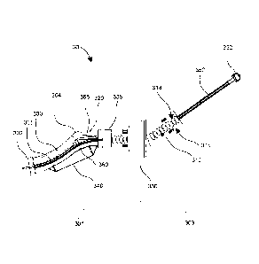
similarly
be treated. The modality for applying the thermal treatment may vary, and the
art
teaches the use of RF electromagnetic energy, laser and ultrasound energy for
heating a
1
CA 2927531 2018-11-02
CA 02927531 2016-04-19
Patent Application Attorney Docket No.: PMI.PCTIB.1000
target region. Some prostate thermal treatments are externally delivered by an
energy delivery device outside the general volume of the prostate or even
outside of the body of the patient, e.g., focused ultrasound surgery. Other
prostate thermal treatments are internally delivered from within the general
volume of the prostate, e.g., using transurethral energy sources delivering
energy from within the urethra outwardly into the surrounding volume of the
prostate.
[0004] Figure 1 illustrates a general arrangement of a male patient in cross
section 10. Existing thermal therapy treatment procedures can vary, but in a
class
of treatments the patient may lie supine as shown and the prostate 100 is
subjected to thermal heating from a therapy applicator source, which can be a
laser, RF antenna, ultrasound transducer or other source. The prostate 100
generally surrounds the urethra. Therefore, a class of treatments inserts a
narrow
applicator (not shown) into the urethra 120 of the patient and guides the
active
portion of the applicator until it is substantially surrounded by the prostate
100.
This type of treatment is called transurethral because it delivers energy into
the
prostate 100 from within the urethra 120.
[0005] An unwanted side effect of the heating of the diseased tissue can be
the
over-heating of adjacent non-diseased tissue and organs. This is because the
heating effects of the thermal therapy procedure have a finite spatial
distribution
that makes it difficult or impossible to fully heat the target zone while not
heating
the surrounding volumes at all. Also, the living body causes heat conduction
and
perfusion to spread the thermal therapy heat to volumes in the vicinity of the
intended target volume. Specifically, as an example, in the thermal therapy of
the
2
CA 02927531 2016-04-19
Patent Application Attorney Docket No.: PMI.PCTIB.1000
prostate, the rectum 110 and other healthy tissues near the prostate 100 can
be
heated beyond what is safe or healthy for the patient. It is desired to limit
the
thermal dose or maximum temperature applied to these tissues, e.g., to the
rectum wall 112 proximal to the prostate 120. The term "proximal" is used
herein
as commonly used in patent specifications to denote things that are adjacent
to
or near one another.
[0006] Some existing protocols employ cooling methods and devices to keep
the temperature rise in healthy tissues around the target volume to within a
safe
limit. These protocols, e.g., US Pub. No. 2011/0319748 Al, disclose a heat
exchange apparatus that is placed into a body cavity (e.g., the rectum through
orifice 130) and that receives a temperature-controlled cooling fluid (e.g.,
water)
to cool the rectum during the thermal therapy of the prostate 100. The present
application is directed to a mechanically and thermally optimized cooling
device
for cooling the rectum 110 and its walls 112 during thermal therapy procedures
in its vicinity, including during thermal therapy to the prostate 100.
Summary
[0007] Example embodiments described herein have innovative features, no
single one of which is indispensable or solely responsible for their desirable
attributes. The following description and drawings set forth certain
illustrative
implementations of the disclosure in detail, which are indicative of several
exemplary ways in which the various principles of the disclosure may be
carried
out. The illustrative examples, however, are not exhaustive of the many
possible
embodiments of the disclosure. Without limiting the scope of the claims, some
of
the advantageous features will now be summarized. Other objects, advantages
3
CA 02927531 2016-04-19
Patent Application Attorney Docket No.: PMI.PCTIB.1000
and novel features of the disclosure will be set forth in the following
detailed
description of the disclosure when considered in conjunction with the
drawings,
which are intended to illustrate, not limit, the invention.
[0008] In an aspect, the invention is directed to an endocavity thermal
control
device. The device includes an elongated body having an insertable portion for
insertion into a rectum of a patient and an external portion that remains
external
to the rectum, wherein the insertable portion includes a distal portion and a
proximal portion disposed at with respect to one another, the body angle from
100 to 150 degrees. The body angle may be obtuse (i.e., greater than 90
degrees
but less than 180 degrees).
[0009] The device also includes a fluid circuit in the body that substantially
extends from the external portion to the insertable portion, the fluid circuit
configured to circulate a thermal fluid into and out of the insertable
portion. The
device also includes a thermal window disposed on a surface of the insertable
portion, the thermal window configured to be positioned adjacent to a prostate
when the device is inserted into the rectum, the thermal window in thermal
communication with the thermal fluid.
[0010] In another aspect, the invention is directed to a method of controlling
a
temperature of a prostate during thermal therapy of a patient. The method
includes inserting an endocavity thermal control device into a rectal cavity
of the
patient, the device comprising an elongated body having an insertable portion
and an external portion, wherein the insertable portion includes a distal
portion
and a proximal portion disposed at a body angle with respect to one another,
the
body angle from 100 to 150 degrees. The method also includes positioning the
4
CA 02927531 2016-04-19
Patent Application Attorney Docket No.: PMI.PCTIB.1000
body to conform to a notch in a rectal wall adjacent to an apex of the
prostate,
the notch formed when a thermal therapy device is inserted into a urethra of
the
patient. The method also includes inflating a balloon disposed on the body of
the
device. The method also includes pressing the balloon against a first rectal
wall
distal to the prostate to cause a thermal window on the body to contact a
second
rectal wall proximal to the prostate. The method also includes circulating a
thermal fluid in a fluid circuit in the body, the fluid circuit extending from
an
external portion to an internal portion of the body, the thermal fluid in
thermal
communication with the thermal window.
In the Drawings
[0011] For a fuller understanding of the nature and advantages of the present
invention, reference is be made to the following detailed description of
preferred
embodiments and in connection with the accompanying drawings, in which:
[0012] Figure 1 illustrates a cross sectional view of a male patient according
to
the prior art;
[0013] Figure 2 illustrates a portion of a male patient undergoing thermal
therapy treatment;
[0014] Figure 3 illustrates a side view of an endocavity thermal control
device 30
according to an embodiment;
[0015] Figure 4 is a side view of endocavity thermal control device inserted
into
a male rectum according to an embodiment;
CA 02927531 2016-04-19
Patent Application Attorney Docket No.: PMI.PCTIB.1000
[0016] Figure 5 is a perspective view of an endocavity thermal control device
according to an embodiment;
[0017] Figure 6 is a cross section of a representative portion of an
insertable
portion of an endocavity thermal control device;
[0018] Figure 7 is a side view of an endocavity thermal control device
according
to an embodiment;
[0019] Figure 8 is a perspective view of an endocavity thermal control device
according to an embodiment; and
[0020] Figure 9 is a side view of the endocavity thermal control device
illustrated
in Figure 8.
Detailed Description
[0021] Thermal therapy procedures can benefit from spatially designed cooling
to tissues and organs that are not diseased but that lie near the thermal
therapy
target zone. In the case of thermal therapy of the prostate, as an example, it
is
helpful to cool the rectum and rectal walls near the prostate to avoid over-
heating
these tissues. The apparatus described below will provide a much-needed
controllable and configurable cooling profile within a patient's rectum for
use with
prostate thermal therapy and in some aspects with ultrasound thermal therapy
of
the prostate.
[0022] It is to be understood that the present disclosure is often illustrated
in the
context of an endocavity being the rectum, but the present invention is not so
limited, and can be applied to other cavities as would be appreciated by those
6
CA 02927531 2016-04-19
Patent Application Attorney Docket No.: PMI.PCTIB.1000
skilled in the art with suitable modifications to the size and form factor of
the
device, without departing from the spirit of the invention. It is also to be
understood that the present disclosure can be applied to cooling as well as to
heating. For example, the device can be used to remove thermal energy or lower
the temperature of a cavity and surrounding tissue, but can be used to add
thermal energy or raise the temperature of a cavity and surrounding tissue as
needed and depending on the medical procedure at hand.
[0023] Figure 2 illustrates a portion 20 of a male patient undergoing thermal
therapy treatment. An applicator 200 is inserted through the male urethra (not
illustrated) until it is adjacent to the prostate 100. As discussed above, the
applicator 200 can include a laser, an RF antenna, an ultrasound transducer or
other heat source. The inserted applicator 200 applies pressure to the lower
portion 101 of the prostate 100. The pressure causes a displacement 102 of the
lower portion 101 of the prostate 100. The displacement 102 is generally
towards
the applicator 200 and away from the rectum 110. The displacement 102 can
cause a gap or notch 115 (illustrated by dotted lines) along the rectum wall
112
adjacent to the displacement 102 of the prostate 100. The displacement 102 of
the prostate 100 occurs proximal to an apex 135 of the prostate 100. The notch
115 has a notch angle 125 which can be defined by lines parallel to the rectum
wall 112 proximal and distal to the notch 115. Base 140 and apex 135 are on
opposing sides of the prostate 100.
[0024] In general, the notch angle 125 is between a first line 210 that is
generally
parallel to the rectum wall 112 proximal to the notch 115 and a second line
220
that is generally parallel to the rectum wall distal to the notch 115. The
notch
7
CA 02927531 2016-04-19
Patent Application Attorney Docket No.: PMI.PCTIB.1000
angle can be about 75 degrees to about 175 degrees, about 100 degrees to
about 150 degrees, about 115 to about 130 degrees, about 125 degrees, or any
value between any of the above ranges. As used herein, "about" means plus or
minus 10% of the relevant value. In addition, the notch 115 has a radius of
about
to about 20 mm, about 10 to about 15 mm, about 12 mm, or any value
between any of the above ranges. It is to be appreciated that the particular
examples and embodiments appearing herein are exemplary and for the purpose
of illustration only. Those skilled in the art will understand that the
present
methods and devices can be applied in other particular embodiments depending
on the circumstance at hand.
[0025] Figure 3 illustrates a side view of an endocavity thermal control
device 30
according to an embodiment. The device shown is designed and configured for
cooling of the rectum and rectal wall and nearby tissue in the context of a
prostate thermal therapy procedure. However, the principles illustrated by
this
embodiment can be extended by those skilled in the art for application to
other
procedures and body cavities. In an embodiment, the device 30 is configured to
conform to the rectum of a male patient including a rectal notch caused by the
insertion of a thermal therapy probe, as discussed above.
[0026] The device 30 comprises a body with a frame or shell or housing 300
that
may include one or several parts joined together so as to be substantially
rigid in
their overall frame. The housing 300 can be formed out of one or more
biocompatible materials. For example, the housing 300 can be formed out of one
or more biocompatible rigid plastics such as acrylonitrile butadiene styrene
(commonly referred to as ABS). In addition or in the alternative, the housing
300
8
CA 02927531 2016-04-19
Patent Application Attorney Docket No.: PMI.PCTIB.1000
can be formed out of one or more biocompatible metals, such as stainless steel
or titanium, and/or one or more biocompatible ceramics, such as aluminum
oxide, zirconia, or calcium phospates. The device can be considered as having
a
first insertable or internal portion 301 that is inserted into a patient's
body (e.g., in
the rectal cavity) during a procedure and a second portion 303 that remains
outside of the patient's body. A flange or collar 330 can be positioned to
define
or limit which portions of the device 30 enter the patient's body and which
portions remain outside of the patient's body during use. Collar 330 can be
moveable in some embodiments to allow for custom sizing and positioning of the
collar to define the extent of insertable portion 301. In the alternative, the
second
portion 303 can have a flared shape or an expanding diameter (e.g., a conical
shape) to prevent over-insertion in which case collar 330 is not needed.
[0027] The shell or housing 300 can also be defined by two opposing ends
thereof. One end 302 having a forward tip that is inserted into the patient's
endocavity in advance of the following portions of insertable portion 301; the
other end 352 comprising a terminator or connector that can be coupled to
other
electrical and/or mechanical ports or terminals. Fluid flow plenums are
disposed
near the tip of end 302 for circulating thermal fluid into and then back out
of the
device 30.
[0028] A handle 310 comprises a grip 315 allowing convenient holding of the
device 30 by an operator who can apply torque or force to the device to
insert,
retract or rotate the device 30 within a patient's body. Collar 330 also
assists in
securing the device 30 from inadvertent over-insertion or unwanted movement
and can help secure the operator's hand to the handle 310 while using the
device
9
CA 02927531 2016-04-19
Patent Application Attorney Docket No.: PMI.PCTIB.1000
30. In addition, the collar 330 can shield the operator's hand from contacting
the
patient's skin proximal to the endocavity (e.g., to prevent contamination).
The
collar 330 can be moved to discrete positions at notches or raised ribs 318
along
the grip 315 to vary the maximum depth of insertion of device 30 in the
endocavity. The notches/raised ribs 318 can mate with complementary features
(raised ribs or notches) of the collar 330 to mechanically secure the collar
330 at a
given location.
[0029] Electrical and/or fluid conduits 360 pass through a shaft 350 so that
they
are terminated in suitable connection points at terminus 352. For example,
electrical sensor wires may pass in and out of the body 300 of the device 30
to
deliver temperature measurements measured by temperature sensors (e.g.,
thermocouples) disposed at one or more locations in the device 30 or on the
external surface of the device 30. Other actuators and sensors may also be
incorporated into the device as needed.
[0030] The fluid conduits 360 can carry a thermal control fluid into and out
of the
device 30 to control the temperature of a patient's endocavity. The fluid and
electrical conduits 360 within the device 30 are described further below, and
can
extend to and from the ends 302, 352 of the device 30 and to points in
between.
[0031] A thermal exchange (e.g., heating or cooling) window 320 is formed into
one face of the housing 300, which is the primary place heat is exchanged
between the thermal control fluid inside the device and the patient's body
surrounding the device. The window 320 can be constructed out a material that
(a) has a high thermal conductivity so as to transfer heat from the tissue to
the
thermal control fluid, (b) has a high mechanical strength to be durable, (c)
is rigid
CA 02927531 2016-04-19
Patent Application Attorney Docket No.: PMI.PCTIB.1000
to maintain its shape under pressure, (d) has a similar acoustic impedance to
the
thermal control fluid to minimize reflection of incident ultrasound energy,
(e) has a
similar magnetic susceptibility to the thermal control fluid to minimize the
introduction of magnetic susceptibility artifacts, (f) is biocompatible, and
(g) is MRI
compatible. For example, the window 320 can be formed of titanium, aluminum,
or polyethylene. In a specific embodiment, the window 320 includes
polyethylene
and/or a polyethylene terephthalate having a thickness of about 0.001 inches
to
about 0.003 inches or about 0.002 inches
[0032] The window 320 can have a longer extent than the extent of the nearby
prostate organ so that axial placement of the device 30 is not an overly
sensitive
operation (leaving some room for error in the axial placement of the device
20). In
some embodiments, the window 320 extends from a bend 304 in the housing
300 to the front tip 302. In some embodiments, the widow extends from a neck
335 to the front tip 302, the neck 335 disposed between the bend 304 and the
collar 330. The neck 335 can be about 15 to about 45 mm or about 30 mm axially
from the bend 304. Again, the particular examples above are provided to
illustrate the nature of the invention, and those skilled in the art may
devise
equivalent, similar or alternative aspects equally comprehended by this
disclosure.
[0033] A variable volume fluid-fillable balloon or bladder 340 is disposed on
a
side of the housing 300, typically opposing the side of the window 320 and/or
the bend 304. The operator can control a fluid (e.g., with a manual or
automated
syringe) to inflate or deflate the balloon or bladder 340. The balloon or
bladder
340 can be filled with a fluid such as air, water, oil, saline, gel, or an
aqueous
11
CA 02927531 2016-04-19
Patent Application Attorney Docket No.: PMI.PCTIB.1000
solution, that can cause balloon or bladder 340 to increase or decrease in
volume
and cross sectional girth. When expanded, the balloon or bladder 340 pushes
against the walls of the endocavity, which in turn causes the entire device 30
including the thermal exchange window 320 to be pressed against the walls of
the endocavity proximal to the window 320. The balloon 340 can be operated by
the operator using a control setting on the handle 310 of the device 30 or
remotely by way of a driving signal applied to a pressure actuator, pump, or
other
mechanism for forcing fluid (gas, liquid) into or out of the balloon 340 to
control
its size. In some embodiments, the operator connects a syringe to the device
30
(e.g., at a port in terminus 352) to fill the balloon 340. The syringe
controlled
manually or automatically to force fluid into or out of the balloon 340. In a
non-
limiting example, the balloon 340 can be inflated to about 10 mm to about 20
mm, 20 mm to about 30 mm, about 15 mm, about 25 mm, or an value
therebetween, in diameter outwardly from the body 300 of device 30.
[0034] Housing 300 may be manufactured in a number of sizes and geometries.
In one example, the housing 300 has a length and general diameter suited to
the
medical procedure and endocavity it is being used with. Housing 300 can
include
bent, curved or contoured features as shown to adapt the device 30 for rectal
cooling applications according to the general size and shape of an expected
endorectal cavity. A bend 304 defines a general change in the axial direction
of
the housing 300 of device 30. In some embodiments, the bend 304 is configured
to align with a position and/or angle of the notch 115 on the rectal wall 112,
as
discussed above. For example, the bend 304 can have a bend angle of 75
degrees to about 175 degrees, about 100 degrees to about 150 degrees, about
12
CA 02927531 2016-04-19
Patent Application Attorney Docket No.: PMI.PCTIB.1000
115 to about 130 degrees, about 125 degrees, or any value between any of the
above angles. Once again, the present disclosure illustrates the invention by
way
of particular examples, which are not intended to be exhaustive or exclusive
of
the applications and embodiments possible under the invention.
[0035] The device 30 can also have a curved contour in some portions to fit
more securely and closely around an anatomy of interest. For example, the
insertable portion 301 can include a curve 305 that extends from the bend 304
to
the forward end 302. The curve 305 is generally upward or concave so that the
forward end 302 is angled towards the bend 304 and away from the patient's
spine (not illustrated). The curve 305 can be defined as an arc of a circle
having a
given radius. An increase in the radius decreases the curvature of curve 305.
In
some embodiments, the device 30 has a straight or a substantially straight
contour (i.e., a "curve" defined by a "circle" having an infinite radius). In
some
embodiments, the curve 305 is defined by a circle having a radius of about 50
mm to about 200 mm, about 75 mm to about 175 mm, about 100 mm to about
150 mm, about 125 mm, or any range between any of the above values. In a
particular embodiment, the curve 305 is defined by a circle having a radius of
about 110 mm. In some embodiments, the curve 305 is defined by a circle having
a radius of greater than 200 mm. Plastics and injection molded polymers and
cast
materials can be used to make a rigid or substantially rigid housing 300 of
the
desired shape and size for an application at hand.
[0036] It has been observed by the present inventors that gas pockets or
bubbles may tend to accumulate locally near certain parts of an endocavity. In
rectal cooling applications, gas can collect at interfaces between the device
30
13
CA 02927531 2016-04-19
Patent Application Attorney Docket No.: PMI.PCTIB.1000
and the rectal wall, e.g., in the notch discussed above. The shape of the
exemplary device 30 including the bend 304 can minimize or prevent such gas
bubbles from forming. Furthermore, inflating expandable balloon 340 causes the
upper side of device 30 to press against the rectal walls between device 30
and
the prostate, moving unwanted gas bubbles away from that interface. Such gas
bubbles can cause reflection of ultrasound energy, which can cause unwanted
heating of the endocavity tissue proximal to the reflection. In addition, the
air
bubbles can cause MRI imaging artifacts that make it difficult to position the
device 30 and/or to view the surrounding tissue. Further, the air bubbles are
insulating and thus reduce the effectiveness of the thermal controls of device
30.
[0037] Air may initially fill the fluid conduits 360 running through the
thermal
control device 30, especially if the device 30 is being used for the first
time, after
it has been in storage, or if the device is inserted into the patient outside
of the
treatment/imaging chamber. In some cases, it is more economical and efficient
for the practitioner or treatment facility to spend the time inserting the
device
into the patient in a separate room prior to taking the patient into the
treatment
room, e.g., a MRI imaging chamber. Here, any air or gas that was in the
thermal
fluid tubes 360 of the device is first purged from the device 30 prior to use
so that
only a desired cooling fluid (e.g., sterilized water or saline solution) is
present in
the fluid circuit of the device during use. For example, this gas purging step
can
take place once the patient is brought into the treatment/imaging chamber. In
the present embodiment, it is desired to avoid air pockets in the device 30
near
the thermal exchange window 320 also because such inclusions could inhibit the
thermal interaction between the device 30 and the adjacent tissue being
14
CA 02927531 2016-04-19
Patent Application Attorney Docket No.: PMI.PCTIB.1000
controlled. In addition, air pockets/bubbles can cause MRI imaging artifacts
that
make it difficult to position the device 30 and/or to view the surrounding
tissue. If
the device 30 is used for cooling, the presence of gas bubbles or a layer of
unwanted gas having poor thermal conductivity along the interior of thermal
exchange window 320 would degrade the performance of the device 30. The air
bubbles can also cause ultrasound reflection, as discussed above. Accordingly,
purge jet 365 allows for removal of such unwanted gas pockets and bubbles from
the vicinity of the thermal exchange window 320. The purge jet 365 is disposed
at the top of housing 300 in the insertable portion 301 of device 30. In an
aspect,
the fluid purge jet 365 provides a turbulent high velocity fluid stream (e.g.,
water)
to dislodge trapped bubbles from the vicinity of said thermal exchange window
320.
[0038] In an aspect, the thermal fluid of the device 30 may be water, e.g.,
sterilized water. In a further aspect, the fluid may be water mixed with an
appropriate surfactant to reduce surface tension of said water and/or to match
the hydrophobicity of the water to that of the device's thermal exchange
window
320. This will allow small air bubbles to detach from the window 320 and to
coalesce elsewhere, or to be washed away by the flow of water. In a non-
limiting
example, the surfactant may comprise Span 80 (sorbitan monooleate) and/or
Tween 80 (polysorbate 80), or similar substances. The thermal fluid can also
include manganese chloride (MnCl2) to reduce and/or eliminate MRI imaging
artifacts due to fluid flow.
[0039] Figure 4 is a side view of an endocavity thermal control device 40
inserted into a male rectum 110 according to an embodiment. The device 40
CA 02927531 2016-04-19
Patent Application Attorney Docket No.: PMI.PCTIB.1000
includes an insertable portion 401 and a second portion 403. The insertable
portion 401 includes a bend 404 that aligns with the notch 115 proximal to the
lower portion 101 of prostate 100. As discussed above, the notch 115 is
located
proximal to the apex 135 of the prostate. The bend 404 and the notch 115 can
have the same or different angles 425, 125, respectively, and can have any of
the
angles discussed above. Notch angle 125 is not illustrated in Figure 4 for
clarity.
In some embodiments, the bend angle 425 and the notch angle 125 are each
about 135 degrees. A balloon 440 can inflate below the bend 404 and can press
against the wall 112 of the rectum 110, which can cause the device 40
including
its cooling window (not illustrated), to contact the wall 112 adjacent to the
prostate 100. The device 40 can lower or maintain the temperature of the
prostate 100 during thermal treatment with probe 200.
[0040] The second portion 403 of the device 40 has a flared or bulbous handle
410 that increases in width or radius from the middle of the device 40 to the
end
452. The increasing width of the handle 410 can prevent over insertion of the
device 40 into a patient (e.g., into the rectum 110 of a patient). In addition
or in
the alternative, the increasing width of handle 410 can prevent or reduce
movement of the device 40 after it has been inserted into the endocavity. The
flared/bulbous handle 410 can also enhance control of the rotational
orientation/alignment of the device 40 in the endocavity. For example, an
operator rotating a handle having a relatively large diameter can move its
circumference further for a given degree of rotation than a handle having a
relatively smaller diameter.
16
CA 02927531 2016-04-19
Patent Application Attorney Docket No.: PMI.PCTIB.1000
[0041] Figure 5 is a perspective view of an endocavity thermal control device
50
according to an embodiment. The device 50 includes a thermal exchange
window 520 that may extend from the tip 502 to the neck 535. Since the thermal
exchange window 520 is disposed on either side of the bend 504, the device 50
can provide adequate thermal regulation for a patient without having to be
placed precisely in the relevant endocavity. For example, the device 50 can
still
provide heating or cooling to the prostate even if the bend 504 is not aligned
with the notch in the rectal wall. In addition, in some patients the prostate
extends on both sides of the notch. In order for the device 50 to provide
adequate cooling for such patients, the thermal exchange window 520 can also
extend across the notch so it is adjacent the prostate on both sides of the
notch.
[0042] Figure 5 also illustrates that the tip 502 can have flutes or channels
506
for example as illustrated in tip 502A. The flutes 506 can provide venting of
air
trapped at the tip 502, 502A when the device 50 is inserted into the
endocavity.
Thus, the flutes 506 can prevent or reduce the introduction of air into the
endocavity on insertion of the device 50, which can prevent or reduce air
bubbles
caused by insertion of the device 50. The tip 502A has four flutes 506 but in
some
embodiments there are additional or fewer flutes 506. For example, the tip
502A
can have 3 to 8 flutes 506, or any value therebetween such as 6 flutes. Each
flute
506 can have a width of about 1 mm to 2 mm or about 1.5 mm, and a depth of
about 0.5 mm to about 1.5 mm or about 0.75 mm. In some embodiments, the
flutes 506 have a variable or non-uniform width and/or depth.
[0043] A lubricant can be used on the exterior of the device 50 to enhance
patient comfort and to minimize bubble formation, for example as the device 50
17
CA 02927531 2016-04-19
Patent Application Attorney Docket No.: PMI.PCTIB.1000
is inserted into the endocavity. The lubricant can be water based, transparent
to
ultrasound and MRI, and bacteriostatic. The lubricant should have a low enough
viscosity so as to not occlude the flutes 506, and not to trap new bubbles as
the
lubricant is applied to the device. Since gas (e.g., air) can scatter or
reflect energy
waves in the surrounding tissues, the presence of gas bubbles or pockets or
voids
is generally to be avoided during ultrasound or other thermal therapies. In
the
case of ultrasound thermal therapy, unwanted gas pockets and bubbles
interacting with the applied ultrasound field can cause undesired heating of
tissues in the vicinity of the bubbles or other unintended consequences of the
field-bubble interaction. In some embodiments, the lubricant can be a
urological
gel. In particular embodiments, the lubricant can be ENDOSGELO (FARCO-
PHARMA GmbH) or MUKOO (Cardinal Health Canada Inc.).
[0044] Figure 6 is a cross section 600 of a representative portion (through
line 6-
6) of the insertable portion of the device. The cross section 600 includes a
thermal exchange window 620, an inner housing 630, and fluid egress channels
640. A fluid cavity 625 is defined between the thermal exchange window 620 and
the inner housing 630. The inner housing 630 can include a biocompatible rigid
plastic, such as ABS. The fluid cavity 625 can have a thickness 621 of about
1.25
mm to about 2.5 mm including about 1.5 mm, about 1.75 mm, about 2.0 mm,
about 2.25 mm, or any value between any of these numbers. The thickness 621
can be uniform or variable along the length of the window 620. In some
embodiments, the window 620 has a thickness 621 of about 2.25 mm at or
proximal to the bend and a thickness 621' (not illustrated) of about 1.5 mm at
or
proximal to the tip, with a tapered thickness therebetween. The foregoing
18
CA 02927531 2016-04-19
Patent Application Attorney Docket No.: PMI.PCTIB.1000
examples, like the other examples described herein, are provided for the sake
of
illustration and not intended to limit the scope of the invention.
[0045] As illustrated in Figure 6, the cross section 600 is generally oval in
shape.
The oval shape has a width 660 and a height 670. The width 660 is selected to
be
large enough to cover the tissue or organ 680 (e.g., prostate) to be
temperature
controlled during therapy. In some embodiments, the width 660 is about 15 mm
to about 30 mm including about 18 mm, about 20 mm, about 22 mm, about 24
mm, about 26 mm, about 28 mm, or any width between any two of the foregoing
widths. The height 670 can be about. The window 620 extends along the
perimeter of the oval to form a horseshoe shape or an upside down "U" shape.
As such, the window 620 extends along at least a portion (e.g., half) of the
height
670 of the oval. This allows the device to be positioned in the endocavity
with
some rotational error. For example, the device can be rotated about 10 degrees
to about 20 degrees or about 15 degrees off center from the organ 680 and the
window 620 will still be positioned adjacent the organ 680 to provide
temperature control thereto. The rotational error also prevents the inner
housing
630 from being exposed to (e.g., in line of sight of) the ultrasound elements
in
the applicator, which would undesirably cause the housing 630 to heat up.
Although the cross section 600 is illustrated as oval, other cross sectional
shapes
can be used consistent with this disclosure.
[0046] In operation, a fluid (e.g., water) is pumped into the device from the
handle (e.g., through a fluid port) through the fluid cavity 625 to the tip of
the
device. The fluid fills a fluid plenum and then follows a return path through
the
fluid egress channels 640.
19
CA 02927531 2016-04-19
Patent Application Attorney Docket No.: PMI.PCTIB.1000
[0047] A pump or vacuum can be applied to the fluid egress channels 640, to
circulate the fluid. The fluid can pass through an external heat exchanger to
heat
or cool the fluid as desired. Temperature feedback can be used to control the
heat exchanger, such as the temperature of the prostate measured using MRI.
The circulating fluid causes the thermal exchange window 620 to increase or
decrease in temperature depending on the relative temperature of the fluid.
Likewise, the thermal exchange window 620 conducts thermal energy to or from
body fluids or tissue in contact with the window 620, such as the internal
walls of
the rectal cavity. Contact between the window 620 and the internal walls can
be
improved with one or more inflatable balloons, as discussed above. The cooled
or warmed walls of the rectal cavity (or other endocavity) can cause the
prostate
to be cooled or warmed, which can maintain the temperature of the prostate
during a thermal therapy procedure. A temperature of the prostate can be
measured during therapy (e.g., through MRI) and the temperature of the thermal
fluid can be adjusted accordingly.
[0048] Figure 7 is a side view of an endocavity thermal control device 70
according to an embodiment. The device 70 includes an elongated insertable
portion 701 and a truncated second portion 703. A bend 704 connects the
insertable and second portions 701, 703. In general, the device 70 appears
similar to a hockey stick in shape. A cooling window 720 is disposed along a
surface 721 of the device 720 from tip 702 to a portion 715 between the bend
704 and the second end 752. A flexible or rigid tube 755 connects to the
second
end 752 for circulating a thermal fluid in the device 70, as discussed above.
In
some embodiments, multiple tubes 755 and ports connect to the second end 752
CA 02927531 2016-04-19
Patent Application Attorney Docket No.: PMI.PCTIB.1000
of the device 70. For example, the tubes 755 can include a balloon fill port
and
tube, a fluid inlet port and tube, a fluid outlet pot and tube, and a purge
port and
tube. In some embodiments, the purge port can be connected to the inlet tube
internally in the second portion 703.
[0049] Figure 8 is a perspective view of an endocavity thermal control device
80
according to an embodiment. The device 80 includes a plurality of ports 810
for
fluid and electrical connects to the device 80. Figure 9 is a side view of the
device
80 illustrated in Figure 8.
[0050] The present design therefore allows for a safer and more effective
cooling
device when used in endorectal temperature control (e.g., cooling or heating)
applications. In an aspect, the overall shape of the device is angled to
generally
fit a typical rectal cavity of a patient, including by angling the tip end of
the
device away from the patient's spine to allow for insertion of the device into
the
needed position even with a patient having a smaller rectum. In another
aspect,
the device is contoured to fill an anterior "notch" in the rectum, which is
typically
caused by or accentuated by the presence of the thermal therapy device in the
nearby urethra (e.g., in ultrasound transurethral thermal therapy). In yet
another
aspect, accounting for and filling in said "notch" brings the cooling device's
cooling window closer to the prostate and prostate-rectum interface where
cooling is needed the most. In still another aspect, the device's cooling
window
may be curved or contoured to follow a general contour of the prostate. In
another aspect, the device includes an expandable or inflatable element such
as a
balloon or bladder, on one side thereof, which can controllably increase in
volume (be inflated) to cause the device to be pressed more firmly against one
21
CA 02927531 2016-04-19
Patent Application Attorney Docket No.: PMI.PCTIB.1000
side of the endocavity in which it is inserted, e.g., to press the device's
cooling
window against the rectal wall adjacent to the prostate. Other aspects include
a
handle with an adjustable collar for securing the device at the proper depth
in the
patient's endocavity. The handle portion of the device may include control
features such as balloon/bladder inflation controls, on/off controls and other
actuators and user interface elements. In some aspects the above design avoids
unwanted air gaps or bubbles or other gas inclusions from forming or remaining
in the device or in the endocavity. Such bubbles or inclusions can adversely
affect
imaging as well as thermal treatment in the patient because they pose magnetic
susceptibility and impedance mismatch interfaces (e.g., gas-liquid or gas-
tissue
interfaces) which can introduce magnetic susceptibility artifacts in MRI
images,
reflect ultrasound, laser and RF energy and will scatter or impede the
propagation of other therapeutic waves or energy fields in and near the
treatment
zone.
[0051] The above-described device therefore effectively controls the
temperature, e.g., by cooling, in and proximal to an endocavity in which it is
inserted, e.g., the rectum of a male patient undergoing thermal therapy, e.g.,
transurethral ultrasound thermal therapy. Those skilled in the art will
appreciate
the application of the present designs and concepts, including with
predictable
and equivalent variations adapted to other procedures and cavities in a
patient's
body as applicable.
[0052] The present invention should not be considered limited to the
particular
embodiments described above, but rather should be understood to cover all
aspects of the invention as fairly set out in the present claims. Various
22
CA 02927531 2016-04-19
Patent Application Attorney
Docket No.: PMI.PCTIB.1000
modifications, equivalent processes, as well as numerous structures to which
the
present invention may be applicable, will be readily apparent to those skilled
in
the art to which the present invention is directed upon review of the present
disclosure. The claims are intended to cover such modifications.
[0053] What is claimed is:
23