Language selection

Search

Patent 2927598 Summary

Third-party information liability

Some of the information on this Web page has been provided by external sources. The Government of Canada is not responsible for the accuracy, reliability or currency of the information supplied by external sources. Users wishing to rely upon this information should consult directly with the source of the information. Content provided by external sources is not subject to official languages, privacy and accessibility requirements.

Claims and Abstract availability

Any discrepancies in the text and image of the Claims and Abstract are due to differing posting times. Text of the Claims and Abstract are posted:

  • At the time the application is open to public inspection;
  • At the time of issue of the patent (grant).
(12) Patent: (11) CA 2927598
(54) English Title: VARIABLE GEOMETRY CONTINUOUS TRACK
(54) French Title: GLISSIERE CONTINUE A GEOMETRIE VARIABLE
Status: Expired and beyond the Period of Reversal
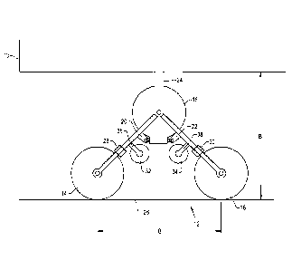
Bibliographic Data
(51) International Patent Classification (IPC):
  • A01B 73/02 (2006.01)
(72) Inventors :
  • HARNETIAUX, TRAVIS L. (United States of America)
(73) Owners :
  • CNH INDUSTRIAL AMERICA LLC
(71) Applicants :
  • CNH INDUSTRIAL AMERICA LLC (United States of America)
(74) Agent: GOWLING WLG (CANADA) LLP
(74) Associate agent:
(45) Issued: 2020-04-14
(22) Filed Date: 2016-04-19
(41) Open to Public Inspection: 2016-12-30
Examination requested: 2018-06-27
Availability of licence: N/A
Dedicated to the Public: N/A
(25) Language of filing: English

Patent Cooperation Treaty (PCT): No

(30) Application Priority Data:
Application No. Country/Territory Date
14/754,954 (United States of America) 2015-06-30

Abstracts

English Abstract


A continuous track assembly having forward and rearward track engaging wheels
with a
intermediate track engaging wheel position between them. A continuous track
extends over the
wheels. A foldable frame journals the wheels and is displaceable between a
position where the
track engaging wheels are in substantially the same plane and another position
in which they are
in a triangular configuration.


French Abstract

Un ensemble de glissière continue ayant des roues de mise en prise de glissière avant et arrière avec une position de roue de mise en prise de glissière intermédiaire entre celles-ci est décrit. Une glissière continue sétend sur les roues. Un cadre pliable supporte les roues et peut être déplacé entre une position dans laquelle les roues de mise en prise de piste sont sensiblement dans le même plan et une autre position dans laquelle elles sont dans une configuration triangulaire.

Claims

Note: Claims are shown in the official language in which they were submitted.

WHAT IS CLAIMED IS:
1. A continuous track assembly comprising;
a forward track-engaging wheel;
a rearward track-engaging wheel;
an intermediate track-engaging wheel positioned between said forward and
rearward
track-engaging wheels;
a continuous track extending around said wheels;
a foldable frame journaling said wheels and displaceable between a first
position wherein
said wheels are substantially in the same plane and a second position wherein
the wheels form a
triangular configuration, wherein the foldable frame comprises a forward frame
connected to the
forward track-engaging wheel and a rearward frame connected to the rear track-
engaging wheel;
and
an actuator interconnecting the forward frame and the rearward frame for
displacing said
foldable frame between the first and second positions.
2. The continuous track assembly of claim 1 wherein said forward frame and
rearward
frame are each pivotal about said intermediate wheel.
3. The continuous track assembly of claim 2 wherein said forward frame and
rearward
frame are each pivoted about an axis of said intermediate track-engaging
wheel.
4. The continuous track assembly of claim 2 wherein said intermediate track-
engaging
wheel is in line with a structural connection for said continuous track
assembly.
7

5. The continuous track assembly of claim 4 wherein the actuator is
horizontal in both the
first and second positions.
6. The continuous track assembly of claim 1 wherein said foldable frame
includes tension
assemblies for selectively expanding and contracting said forward and rearward
frames to
maintain tension in said continuous track.
7. The continuous track assembly of claim 1 further comprising bogie wheels
mounted on
said frame and positioned to engage said continuous track when said wheels are
substantially in
the same plane and displaced away from said continuous track when said track-
engaging wheels
are in the triangular configuration.
8. A farm implement comprising;
a frame; and,
a plurality of continuous track assemblies for providing ground support to
said frame,
each continuous track assembly comprising:
a forward track-engaging wheel;
a rearward track-engaging wheel;
an intermediate track-engaging wheel;
a continuous track extending around said wheels;
a foldable frame journaling said wheels and displaceable between a first
position wherein
said wheels are in substantially the same plane and a second position wherein
the wheels form a
triangular configuration, wherein the foldable frame comprises a forward frame
connected to the
forward track-engaging wheel and a rearward frame connected to the rear track-
engaging wheel;
8

and
an actuator interconnecting the forward frame and the rearward frame for
displacing said
foldable frame between the first and second positions.
9. The farm implement of claim 8 wherein said foldable frame includes
tension assemblies
for selectively expanding and contracting said foldable frames to maintain
tension in said
continuous track.
10. The farm implement of claim 9 wherein the foldable frame is pivoted
about the center
wheel of the intermediate track-engaging wheel.
11. The farm implement as claimed in claim 10 wherein said foldable frame
is pivoted about
the axis of said intermediate track-engaging wheel.
12. The farm implement of claim 10 wherein said continuous track assemblies
are connected
to said frame through said intermediate wheel.
13. The farm implement as claimed in claim 12 wherein the actuator remains
horizontal in
both the first and second positions.
14. The farm implement as claimed in claim 9 further comprising bogie wheels
mounted on
said frame and positioned to engage said continuous track when said wheels are
substantially in
the same plane and displaced away from said track when said wheels are in the
triangular
configuration.
9

15. The farm implement of claim 8 further comprising:
a power unit mounted on said frame; and,
a power train connecting said power unit to at least one of said endless track
assemblies.
16. The farm implement of claim 15 wherein said power train connects said
power unit to
said intermediate track engaging wheel.
17. A continuous track assembly comprising:
a forward track-engaging wheel;
a rearward track-engaging wheel;
an intermediate track-engaging wheel positioned between said forward and
rearward
wheels;
a continuous track extending around said wheels;
a foldable frame having a forward frame journaling said forward wheel and a
rearward
frame journaling said rearward wheel, the foldable frame being displaceable
between a first
position wherein said wheels are substantially on a same plane and a second
position wherein the
wheels form a triangular configuration; and
an actuator interconnecting said forward and rearward frames for displacing
said foldable
frame between the first and second positions, wherein said foldable frame is
pivotal about an axis
of said intermediate track-engaging wheel, and wherein said intermediate track-
engaging wheel
is in line with a structural connection for said continuous track assembly.

18. The continuous track assembly of claim 17 wherein both the forward
frame and the
rearward frame are configured to pivot about the axis of said intermediate
track-engaging wheel.
19. The continuous track assembly of claim 17 wherein said foldable frame
includes tension
assemblies for selectively expanding and contracting said foldable frames to
maintain tension in
said continuous track.
20. The continuous track assembly of claim 17 further comprising bogie
wheels mounted on
said foldable frame and positioned to engage said continuous track when said
wheels are
substantially on a same plane and displaced away from said track when said
wheels are in the
triangular configuration.
21. A farm implement comprising:
a plurality of continuous track assemblies for providing ground support to
said
implement, the continuous track assemblies each comprising:
a forward track-engaging wheel;
a rearward track-engaging wheel;
an intermediate track-engaging wheel;
a continuous track extending around said wheels;
a foldable frame journaling said wheels and displaceable between a first
position wherein
said wheels are substantially on a same plane and a second position wherein
the wheels form a
triangular configuration; and
an actuator interconnecting said foldable frame and operable to displace said
foldable
frame between said first and second positions, wherein said foldable frame
includes tension
11

assemblies for selectively expanding and contracting said foldable frame to
maintain tension in
said continuous track, wherein the foldable frame is pivoted about an axis of
the intermediate
track-engaging wheel, and wherein said continuous track assemblies are
connected to said frame
through said intermediate wheel.
22. The farm implement as claimed in claim 21 wherein both the forward
frame and the
rearward frame are pivoted about the axis of said intermediate track-engaging
wheel.
23. The farm implement as claimed in claim 21 further comprising bogie
wheels mounted on
said frame and positioned to engage said continuous track when said wheels are
substantially in
the same plane and displaced away from said track when said wheels are in the
triangular
configuration.
24. The farm implement of claim 21 further comprising: a power unit mounted
on said frame;
and, a power train connecting said power unit to at least one of said endless
track assemblies.
25. The farm implement of claim 24 wherein said power train connects said
power unit to
said intermediate track engaging wheel.
26. A continuous track assembly comprising:
a forward track-engaging wheel supported by a forward frame;
a rearward track-engaging wheel supported by a rearward frame;
an intermediate track-engaging wheel positioned between said forward and
rearward
wheels;
12

a continuous track extending around said wheels;
a foldable frame journaling said wheels and displaceable between a first
position wherein
said wheels are substantially on a same plane and a second position wherein
the wheels form a
triangular configuration; and
an actuator interconnecting the forward and rearward frames of said foldable
frame for
displacing said foldable frame between the first and second positions, wherein
the actuator is
parallel to the same plane.
13

Description

Note: Descriptions are shown in the official language in which they were submitted.


CA 02927598 2016-04-19
VARIABLE GEOMETRY CONTINUOUS TRACK
BACKGROUND OF THE INVENTION
1. Field of the Invention
[0001] The present invention relates to continuous track assemblies, and, more
specifically, to
continuous track assemblies having variable geometry.
2. Description of the Related Art
[0002] A recent trend in the farm implement business has been the increasing
use of
continuous tracks in place of wheels for farm implements. The continuous track
offers the
advantage of a lower unit pressure owing to the significantly larger ground
engaging area when
compared to a simple wheel assembly. This is especially advantageous in multi-
row planters
where the added weight of the overall assembly makes it important to provide
ground support
that is does not allow the planter to sink into the soil.
[0003] While the continuous track assemblies provide a lower ground engaging
unit pressure,
they tend to be bulkier which is a problem when employed on planting
implements that are
articulated between a planting and transport position. The continuous track
assembly can
interfere with the planter frame elements as they are folded into a transport
position. In addition,
the continuous track assemblies, because of having a greater ground engaging
area, make it
harder to turn and maneuver the planter when it is in the transport position.
[0004] Accordingly, what is needed in the art is a continuous track assembly
that offers low
ground engaging unit area pressure yet offers easy maneuverability in a
transport position.
SUMMARY OF THE INVENTION
[0005] The present invention seeks to achieve a solution to the above problems
by providing
variable geometry continuous track assemblies.
50946 1

CA 02927598 2016-04-19
[0006] The present invention also solves the above problems in a simplified
and cost effective
way.
100071 In one form, the invention is a continuous track assembly including a
forward track
engaging wheel and a rearward track engaging wheel. An intermediate track
engaging wheel is
positioned between the wheels and a continuous track extends around the
wheels. A foldable
frame journals the wheels and is displaceable between a first position in
which the wheels are in
substantially the same plane and a second position in which the wheels form a
triangular
configuration.
[0008] In another form, the invention is a farm implement having a frame and a
plurality of
ground support assemblies. The ground support assemblies each includes a
continuous track
assembly with forward and rearward track engaging wheels and an intermediate
track engaging
wheel positioned between the wheels. A continuous track extends around the
wheels and a
foldable frame journals the wheels and is displaceable between a first
position in which the
wheels are in substantially the same plane and a second position in which the
wheels form a
triangular configuration.
[0009] One advantage of the present invention is a lower ground engaging unit
pressure in one
configuration and another configuration offering easier maneuverability.
[0010] Another advantage is the provision of a large surface area in one
configuration.
BRIEF DESCRIPTION OF THE DRAWINGS
[0011] The above-mentioned and other features and advantages of this
invention, and the
manner of attaining them, will become more apparent and the invention will be
better understood
by reference to the following description of an embodiment of the invention
taken in conjunction
with the accompanying drawings, wherein:
[0012] Fig. l is a schematic side view of a farm implement with a ground
support assembly
50946 2

CA 02927598 2016-04-19
embodying the present invention shown in a first position; and,
[0013] Fig. 2 is a schematic side view of the ground support assembly of Fig.
1 shown in a
second position.
[0014] Corresponding reference characters indicate corresponding parts
throughout the several
views. The exemplification set out herein illustrates one embodiment of the
invention and such
exemplification is not to be construed as limiting the scope of the invention
in any manner.
DETAILED DESCRIPTION OF THE INVENTION
[0015] Referring to Figs. 1 and 2, there is shown a farm implement 10 with
which the present
invention may be used. Farm implement 10 is shown in abbreviated schematic
fashion, but is
intended to encompass self-propelled farm implements such as tractors,
combines and the like
and towed farm implements such as tillage assemblies and planters, among other
things. The
implements may be self-propelled or may be towed as is the nature of their
duty cycle. Farm
implement 10 has a plurality of continuous track assemblies 12, only one of
which is shown.
Typically if the implement is self-propelled it would have a plurality of
track assemblies such as
4.
[0016] Each track assembly 12 includes a forward track engaging wheel 14, a
rearward track
engaging wheel 16 and an intermediate track engaging wheel 18. Forward track
engaging wheel
14 is supported and journaled for rotation by a frame 20 and rearward track
engaging wheel 16 is
supported and journaled for rotation by a frame 22. Frame members 20 and 22
are pivotally
interconnected as illustrated at the rotational axis of intermediate wheel 18
so that the journaling
component for wheel 18 also functions as the pivot point for frame members 20
and 22 which
can be folded. A frame member 24 journals wheel 18, supports it and
interconnects the track
assembly 12 to the farm implement 10. Depending upon the function the
interconnection 24 may
50946 3

be fixed or may be pivotable to provide maneuvering of the farm implement 10.
[0017] A continuous track 26 is received over wheels 14, 16 and 18 and
provides contact with
the soil over which the farm implement 10 moves. The exact nature of
continuous track 26 is not
shown, but it may be employed as a continuous toothed rubber belt or as
interconnected pivotal
links. A discrete number of links may be pivotally interconnected to form a
continuous belt.
Other forms of continuous track 26 may be employed and continue to use the
benefits of the
present invention.
[0018] Tension assemblies 28 and 30 connected to frames 20 and 22,
respectively expand or
contract to permit an appropriate level of continuous track tension for
different geometries of the
continuous track assembly 12. Bogie wheels 32 and 34 are supported by forward
bogie frame
support 36 and rearward bogie frame support 38 to be journaled and to come in
contact with the
continuous track 26 for support when the assembly is in the configuration
shown in Fig. 1.
[0019] An actuator 40 having an extensible actuator rod 42 is pivotally
connected to frames 20
and 22 through link connectors 44. Actuator 40 is shown in Fig. 1 in its
extended configuration
wherein the axis of wheels 14, 18 and 16 are substantially in the same plane.
[0020] As shown in Fig. 2, the actuator 40 may be actuated to retract and to
move the frames
20 and 22 into a triangular configuration during which the bogie wheels are
displaced out of
contact with the continuous track 26. By displacing the track assemblies 12
between the
configurations of Fig. 1 and 2, the variable geometry provides optimum contact
surface with the
ground and at the same time provides increased maneuverability and
flexibility. When the
configuration is in that shown in Fig. 1, the farm implement is generally in a
field position in
which ground is tilled or seeds planted. In that position a maximum surface
area with the ground
is indicated by A is employed to result in unit pressure areas with respect to
the ground that are
within manageable limits. At this point, the ground clearance Al is at a
minimum. When the
4
CA 2927598 2019-04-17

CA 02927598 2016-04-19
implement 10 is placed in a transport position, the continuous track
assemblies 12 are placed in
the triangular configuration of Fig. 2 so that the ground surface area shrinks
from A to B while at
the same time the ground clearance B' increases. By reducing the unit area the
maneuverability
of the farm implement is enhanced because there is less resistance to turning
movements by
virtue of the lower surface area. In addition, the ground clearance B'
increases to increase the
flexibility of movement over obstacles. Furthermore, when the continuous track
assemblies 12
are utilized in a folding configuration planter, the triangular configuration
of Fig. 2 experiences
less interference with the articulated members of the planter assembly.
[0021] What has been described above is a towed farm implement. The implement
10 may be
made in a self-propelled form by the use of a power unit 46 interconnected to
one of the wheels
14, 16 and 18 to provide a driven track. As herein shown the intermediate
wheel 18 is the driven
wheel via a power train 48. However, any of the other wheels may be driven as
appropriate. It
is to be noted that one or more of the continuous track assemblies 12 in the
farm implement 10
may be driven to as needed for the particular function.
[0022] When the continuous track assemblies 12 are in their in the position
shown in Fig. 1,
the bogie wheels 32 and 34 provide additional support between the various
track engaging
wheels. However, when the continuous track assembly 12 is pivoted to the
position of Fig. 2,
they are taken out of contact with the continuous track 26. The tensioners 28
and 30 properly
accommodate variations in length caused by the variable wrapping of continuous
track 26 around
the track engaging drive wheels.
[0023] While this invention has been described with respect to at least one
embodiment, the
present invention can be further modified within the spirit and scope of this
disclosure. This
application is therefore intended to cover any variations, uses, or
adaptations of the invention
using its general principles. Further, this application is intended to cover
such departures from
50946 5

CA 02927598 2016-04-19
the present disclosure as come within known or customary practice in the art
to which this
invention pertains and which fall within the limits of the appended claims.
50946 6

Representative Drawing
A single figure which represents the drawing illustrating the invention.
Administrative Status

2024-08-01:As part of the Next Generation Patents (NGP) transition, the Canadian Patents Database (CPD) now contains a more detailed Event History, which replicates the Event Log of our new back-office solution.

Please note that "Inactive:" events refers to events no longer in use in our new back-office solution.

For a clearer understanding of the status of the application/patent presented on this page, the site Disclaimer , as well as the definitions for Patent , Event History , Maintenance Fee  and Payment History  should be consulted.

Event History

Description Date
Time Limit for Reversal Expired 2022-10-19
Letter Sent 2022-04-19
Letter Sent 2021-10-19
Letter Sent 2021-04-19
Common Representative Appointed 2020-11-07
Grant by Issuance 2020-04-14
Inactive: Cover page published 2020-04-13
Pre-grant 2020-02-21
Inactive: Final fee received 2020-02-21
Common Representative Appointed 2019-10-30
Notice of Allowance is Issued 2019-09-19
Letter Sent 2019-09-19
Notice of Allowance is Issued 2019-09-19
Inactive: Approved for allowance (AFA) 2019-08-29
Inactive: Q2 passed 2019-08-29
Amendment Received - Voluntary Amendment 2019-04-17
Inactive: S.30(2) Rules - Examiner requisition 2019-03-28
Inactive: Report - No QC 2019-03-25
Letter Sent 2018-07-03
Amendment Received - Voluntary Amendment 2018-06-27
Request for Examination Received 2018-06-27
Request for Examination Requirements Determined Compliant 2018-06-27
All Requirements for Examination Determined Compliant 2018-06-27
Change of Address or Method of Correspondence Request Received 2018-01-10
Inactive: Cover page published 2016-12-30
Application Published (Open to Public Inspection) 2016-12-30
Inactive: First IPC assigned 2016-05-10
Inactive: IPC assigned 2016-05-10
Letter Sent 2016-04-29
Filing Requirements Determined Compliant 2016-04-29
Inactive: Filing certificate - No RFE (bilingual) 2016-04-29
Application Received - Regular National 2016-04-25

Abandonment History

There is no abandonment history.

Maintenance Fee

The last payment was received on 2020-03-12

Note : If the full payment has not been received on or before the date indicated, a further fee may be required which may be one of the following

  • the reinstatement fee;
  • the late payment fee; or
  • additional fee to reverse deemed expiry.

Please refer to the CIPO Patent Fees web page to see all current fee amounts.

Fee History

Fee Type Anniversary Year Due Date Paid Date
Registration of a document 2016-04-19
Application fee - standard 2016-04-19
MF (application, 2nd anniv.) - standard 02 2018-04-19 2018-03-02
Request for examination - standard 2018-06-27
MF (application, 3rd anniv.) - standard 03 2019-04-23 2019-03-05
Final fee - standard 2020-03-19 2020-02-21
MF (application, 4th anniv.) - standard 04 2020-04-20 2020-03-12
Owners on Record

Note: Records showing the ownership history in alphabetical order.

Current Owners on Record
CNH INDUSTRIAL AMERICA LLC
Past Owners on Record
TRAVIS L. HARNETIAUX
Past Owners that do not appear in the "Owners on Record" listing will appear in other documentation within the application.
Documents

To view selected files, please enter reCAPTCHA code :


To view images, click a link in the Document Description column. To download the documents, select one or more checkboxes in the first column and then click the "Download Selected in PDF format (Zip Archive)" or the "Download Selected as Single PDF" button.

List of published and non-published patent-specific documents on the CPD .

If you have any difficulty accessing content, you can call the Client Service Centre at 1-866-997-1936 or send them an e-mail at CIPO Client Service Centre.


Document
Description 
Date
(yyyy-mm-dd) 
Number of pages   Size of Image (KB) 
Description 2016-04-19 6 234
Claims 2016-04-19 4 88
Abstract 2016-04-19 1 12
Drawings 2016-04-19 2 22
Representative drawing 2016-12-02 1 6
Cover Page 2016-12-30 2 33
Claims 2018-06-27 6 182
Abstract 2018-06-27 1 12
Claims 2019-04-17 7 200
Description 2019-04-17 6 237
Representative drawing 2020-03-26 1 5
Cover Page 2020-03-26 1 28
Filing Certificate 2016-04-29 1 188
Courtesy - Certificate of registration (related document(s)) 2016-04-29 1 125
Reminder of maintenance fee due 2017-12-20 1 111
Acknowledgement of Request for Examination 2018-07-03 1 187
Commissioner's Notice - Application Found Allowable 2019-09-19 1 162
Commissioner's Notice - Maintenance Fee for a Patent Not Paid 2021-05-31 1 558
Courtesy - Patent Term Deemed Expired 2021-11-09 1 535
Commissioner's Notice - Maintenance Fee for a Patent Not Paid 2022-05-31 1 551
New application 2016-04-19 4 118
Request for examination / Amendment / response to report 2018-06-27 9 244
Examiner Requisition 2019-03-28 4 209
Amendment / response to report 2019-04-17 18 569
Final fee 2020-02-21 1 42