Note: Descriptions are shown in the official language in which they were submitted.
CA 02927729 2016-04-20
1
BLOWING OR STRETCH-BLOWING MACHINE FOR BOTTLES MADE
OF POLYMER MATERIAL
Description
The present invention relates to a blowing or
stretch-blowing machine for preforms made of polymer
material adapted to transform said preforms into
bottles or containers, and in particular to the
forming half-mold closing mechanism.
Obtaining bottles or containers by blowing
suitable appropriately heated preforms in a mold of
the desired shape is a widely known technique in the
packaging sector, in particular for making bottles or
containers.
There are substantially two different
techniques, simple blowing and stretch-blowing, which
include pneumatic blowing and the concurrent
mechanical stretching of the preform in the mold. In
both cases, the preforms must reach the blowing or
stretch-blowing machine in a thermal condition which
corresponds to the softening point of the material,
so as to be able to be plastically deformed inside
the molds.
Blowing or stretch-blowing machines for preforms
are known and comprise a plurality of openable molds
comprising two half-molds hinged at an end and
CA 02927729 2016-04-20
2
actuated by means of appropriately arranged leverages
sized to allow the opening and closing thereof in
synchronized manner with predetermined steps of
loading of the preforms and of unloading of the
formed bottle. Such leverages are generally operated
by means of a shaped cam coupling, such a coupling
being adapted to provide an alternating motion with
pattern defined by the shape of the cam itself.
In rotating machines, a plurality of molds is
arranged radially about a central rotation axis and
means for opening and closing the molds are
synchronized with the movement of other devices which
cooperate in the operation of the machine, e.g. a
movement device for the entering preforms and the
exiting bottles, or a blowing and movement device of
different components of the molds.
The conventional mold movement and
opening/closing systems are complex and, above all,
not very versatile. Indeed, in order to modify the
opening/closing pattern it is necessary to replace
the cam system with a different one in which the
profile of the cam corresponds to the new movement.
Furthermore, by implying the use of complex
mechanical movement transmission systems, the
conventional machines are subject to high wear and
CA 02927729 2016-04-20
3
thus to frequent and careful maintenance.
The problem addressed by the present invention
is to make available a blowing or stretch-blowing
machine for bottles made of plastic material which
allows to overcome the disadvantages illustrated
above and which is thus simpler to construct,
requiring less maintenance and having greater
flexibility.
Such a problem is solved by a machine as
outlined in the accompanying claims, the definitions
of which form an integral part of the present
description.
Further features and advantages of the present
invention will be apparent from the description of
some exemplary embodiments, given here by way of non-
limiting example with reference to the following
figures:
Figures lA and 1B show perspective views of a
first embodiment of a mold for containers made of
plastic material according to the invention, in two
different operating conditions;
Figures 2A and 2B show views from the bottom of
the mold in figures lA and 1B, in the respective
operating conditions;
Figures 3A and 3B show section side views of the
CA 02927729 2016-04-20
4
mold in figures lA and 1B, in the respective
operating conditions;
Figures 4A and 43 show section side views of a
second embodiment of a mold for containers made of
plastic material according to the invention, in two
different operating conditions;
Figure 5 shows a perspective view of a third
embodiment of a mold for containers made of plastic
material according to the invention in open mold
operating condition;
Figures 6A and 6B show section side views of the
mold in figure 5, in two different operating
conditions;
Figure 7 shows a section side view of the mold
in figure 6A, on which a shaped profile is mounted.
With reference to the figures, reference numeral
1 indicates as a whole an injection forming mold of a
container in blowing or stretch-blowing machines.
Typically, a blowing or stretch-blowing machine
according to the invention is of the rotating type
and comprises a plurality of molds 1 arranged
radially with respect to a substantially vertical
rotation axis of the machine.
By turning about the rotation axis of the
machine, each mold 1 is cyclically carried to a
CA 02927729 2016-04-20
loading station of a preform and/or an unloading
station of a bottle obtained from the preform. The
blowing or stretch-blowing is performed between the
loading of the preform and the unloading of the
bottle.
Each mold 1 comprises a first half-mold 2a and a
second half-mold 2b hinged about a hinge axis 3,
normally parallel to the rotation axis of the
machine. The hinge axis 3 is arranged at an end of
the half-molds 2a, 2b facing towards the axis of the
machine, while the half-molds 2a, 2b on the opposite
end comprise edges 9a, 9b intended to face each other
when the mold 1 is closed.
Each half-mold 2a, 2b is C-shaped in cross
section, comprising a front portion 37a, 37b, a side
portion 38a, 38b and a rear portion 39a, 39b.
The first half-mold 2a and the second half-mold
2b can thus turn about the hinge axis 3 between a
closed mold configuration (Fig. 1A, 2A, 3A, 4A and
6A) and an open mold configuration (Fig. 1B, 2B, 3B,
4B, 5 and 6B). The half-molds 2a, 2b can thus be
opened/closed like two shells of a bivalve shell.
Mold 1 comprises a bottom plate 4 adapted to
cooperate with the half-mold 2a, 2b for closing the
bottom of the mold 1 and vertical/translation
CA 02927729 2016-04-20
6
movement of the bottom plate, for cyclically forming
a closed cavity adapted to receive a preheated
preform and for allowing the expansion of the preform
by blowing or stretch-blowing in the cavity to obtain
a bottle or a container.
The bottom plate 4 slides vertically on a guide
element 46, fixed to the support structure of the
blowing or stretch-blowing machine or of the mold 1,
by means of a slide 47.
The half-molds 2a, 2b comprise an outer face 5a,
5b and an inner face 6a, 6b, respectively. Respective
shaped portions S (shown by way of example in figure
7 relatively to the embodiment in figure 5) are
applied onto the inner faces 6a, 6b, which portions
taken as a whole, with the mold closed, reproduce as
a negative shape the outer shape of the bottle to be
obtained from the preform and delimit the space in
which the preform is expanded.
In some embodiments, such a shaped portion S can
be separated from the half-molds 2a, 2h and is
interchangeable, so as to allow the forming of
bottles having different shapes and sizes. In such a
manner, it is sufficient to replace the shaped
portions S to start the production of different
bottles.
CA 02927729 2016-04-20
7
The half-molds 2a, 2b comprise a bottom opening
from which the lower part of the shaped portions S
protrude, the shaped portions S having, in turn, a
bottom opening at a bottom portion of the bottle to
be obtained, said opening adapted to be closed with
alternate motion by the aforesaid bottom plate 4.
As shown in figure 3, abutment profiles 10a, 10b
are applied on the edges 9a, 9b of the respective
half-molds 2a, 2b.
In preferred embodiments, the abutment profiles
10a, 10b are removable and may be changed in case of
wear.
On one of the two half-molds 2a, 2b (on the
right half-mold 2b, in the example in the figures) a
closing element 19 of the mold 1 is rotationally
mounted, the closing element 19 being adapted to keep
the half-molds 2a, 2b joined during the blowing or
stretch-blowing process.
The movement mechanism of the closing element 19
and the retaining system of the half-molds is
described in patent application EP15164317.8 filed on
20 April 2015 by the same Applicant.
The blowing and stretch-blowing machine of
containers according to the present invention is
characterized in that it envisages an opening/closing
CA 02927729 2016-04-20
8
system of the half-molds 2a, 2b and of the bottom
plate 4 which envisages an independent motorization
instead of the actuation cam. Thus, each mold 1 of
the blowing and stretch-blowing machine comprises its
own motorization which will open/close the half-molds
2a, 2b and bottom plate 4 and will be independent
from the motorization of the machine which in turn
transports the molds 1 along the working path.
The aforesaid motorization for the
opening/closing the half-molds 2a, 2b and the bottom
plate 4 is an actuator with either rotating or linear
movement. Preferred examples of actuators are stepper
motors, preferably either linear or rotating
brushless motors.
Mold 1 according to the invention thus comprises
an actuator which moves a single synchronized
actuation opening/closing mechanism of the half-mold
2a, 2b and of the bottom plate 4.
This embodiment, as described in better detail
below, further to allowing a greater control of the
blowing or stretch-blowing process, it has the
advantage of reducing vibrations, noise and wear of
the machine by virtue of the fact that it is free of
mechanical cams.
In the figures from lA to 3B, it is shown a
CA 02927729 2016-04-20
9
first embodiment of the mold 1 according to the
invention in a close operating condition (figures 1A,
2A and 3A) and in an open operating condition (figure
1B, 2B and 3B).
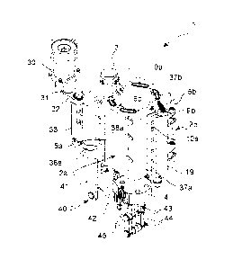
The mold 1 comprises an actuator 30. In the
example shown, the actuator 30 is either a stepper or
a brushless motor of the rotating type coupled to a
ratio motor.
The actuator 30 is placed vertically with the
shaft facing downwards and acts on an eccentric
member 31, in turn hinged to an end of a crank 32.
The opposite end of the crank 32 is instead hinged to
a sliding member 33, which slides horizontally along
a direction defined by a straight line which lies on
the vertical plane that divides the half-molds 2a,
2b.
The sliding member 33 comprises a slide 34
slidingly mounted on guide means 35, which may
comprise a rail or a single rail. The guide means 35
are fixed and are mounted on the support structure of
the blowing or stretch-blowing machine or of the mold
1. The sliding member 33 may thus slide between an
advanced (or closed) position and a retreated (or
open) position.
The sliding member 33 is connected to the two
CA 02927729 2016-04-20
half-molds 2a, 2b by means of respective connecting
rods 36a, 36b.
The first ends of the two connecting rods 36a,
36b are coaxially hinged onto the sliding member 33,
while the opposite ends are hinged at the joint point
between the side portions 38a, 38b and the rear
portions 39a, 39b of the half-molds 2a, 2b,
respectively. In this manner, as shown in particular
in figures 2A and 2B, when the sliding member 33 is
in advanced position, the half-molds 2a, 2b are found
facing along the edges 9a, 9b and the mold 1 is
closed; conversely, when the sliding member 33 is in
the retreated position (figure 2B), the connecting
rods 36a, 36b act on the hinging points with the
half-molds 2a, 2b, taking them to the open position.
It is apparent that all intermediate positions
of the sliding member 33 along the guide means 35
correspond to a different degree of opening of the
half-molds 2a, 2h. As will be explained better below,
the possibility of defining a different degree of
opening of the half-molds 2a, 2b as a function of the
size of the container to be formed allows to optimize
the procfffessing times: indeed, for small size
containers it will not be necessary to open the molds
completely to load the preform and unload the formed
CA 02927729 2016-04-20
11
container, thus reducing the overall time for each
working step and allowing to speed up the production
cycle. This is also the case of larger containers,
because it will still be possible to open the half-
molds 2a, 2b only partially to load the preforms,
which are small.
Another advantage connected to an only partial
opening of the half-molds 2a, 2b resides in the
decrease of the forces in hand and of the vibrations
of the machine.
The sliding member 33 is also operatively
connected to an opening-closing mechanism of the
bottom plate 4.
As shown in the figures, such a mechanism is a
pantograph mechanism. A system of articulated arms 40
is associated with the lower side of the sliding
member 33, the system comprising:
- a first arm 41 having a proximal end and a
distal end, wherein the proximal end is fixed on the
lower part to the sliding member 33;
- a second arm 42, having a proximal end and a
distal end, wherein the proximal end is hinged at the
distal end of the first arm 41;
- a pair of connecting rod-like arms 43, 44,
each having a proximal end and a distal end, wherein
CA 02927729 2016-04-20
12
the respective proximal ends are coaxially hinged to
the distal end of the second arm 42,
and wherein:
- the distal end of a first connecting rod-like
arm 43 is hinged on the lower surface of the bottom
plate 4, and
- the distal end of the second connecting rod-
like arm 44 is hinged to a fixed element 45.
The fixed element 45 is supported by the support
structure of the blowing or stretch-blowing machine
or of the mold 1.
As shown in figures 2A and 2B, in some
embodiments both the first 43 and the second 44
connecting rod-like arms consist of a pair of
parallel arms.
As shown in particular in figures 3A and 3B,
when the sliding member 33 is in an advanced position
(figure 3A), the connecting rod-like arms 43, 44 are
positioned aligned perpendicularly with respect to
the second arm 42, and the bottom plate 4 is in a
raised position (or closed position); conversely,
when the sliding member 33 is in a retreated position
(figure 3B), the connecting rod-like arms 43, 44
assume a V-position and the bottom plate is in a
lowered position (or open position).
CA 02927729 2016-04-20
13
In the embodiment shown in figures from 1A to
3B, the eccentric 31 - crank 32 system for moving the
sliding member 33 allows to operate the mold 1
between the closed position (figures 1A, 2A and 3A)
and a total opened condition (figures 1B, 2B and 3B)
by means of the rotation of the shaft of the rotating
actuator 30 to only one direction. This allows to
avoid the steps of stopping and restarting which can
cause vibrations to the machine. Conversely, a
movement in alternating directions must be envisaged
if it is desired to open the mold 1 only partially
(as mentioned above in the case of small size
containers).
Figures 4A, 4B and figures 5, 6A and 6B show two
alternative embodiments of the mold 1 of the
invention, respectively. In such embodiments, the
operating connection between sliding member 33 and
half-molds 2a, 2b and bottom plate 4 is the same and
consequently will not be described again. Conversely,
such embodiments envisage different types of movement
of the sliding member 3 by means of an actuator 30.
With reference to figures 4A and 4B, the
rotating actuator 30 is connected to an Archimedes'
screw 51, by means of a ratio motor 50.
The Archimedes' screw 51 is operatively
CA 02927729 2016-04-20
14
connected to a movable member 52. The moveable member
52 comprises a tubular portion having internally
bosses which mate with the grooves of the Archimedes'
screw 51. In such a manner, when Archimedes' screw 51
rotates, the movable member 52 moves upwards or
downwards according to the rotation direction of the
Archimedes' screw 51.
The moveable member 52 comprises an outer
support portion 53 comprising a slide 54 arranged
parallel to the Archimedes' screw 51. The slide 54
slides on a guide element 55 fixed onto the support
structure of the blowing or stretch-blowing machine
or of the mold 1. A greater stability of the moveable
member with respect to possible oscillations about
the vertical axis is obtained in this manner.
A pantograph mechanism 56 for horizontal
movement of the sliding member 33 is inferiorly
hinged onto the outer support portion 53 of the
movable member 52.
The pantograph mechanism 56 comprises an
articulated arm 57 having a proximal end hinged on
the outer support portion 53 of the movable member 52
and a distal end. A first 58 and a second connecting
rod-like arm 59 comprising respective proximal and
distal ends are coaxially hinged on the distal end of
CA 02927729 2016-04-20
the articulated arm 57 by means of said proximal
ends. Conversely, the distal end of the first
connecting rod-like arm 58 is hinged onto a fixed
element 60 associated with the support structure of
the blowing or stretch-blowing machine or of the mold
1, while the distal end of the second connecting rod-
like arm 59 is hinged on the sliding element 33.
In this manner, when the movable member 52
slides downwards, following the rotation in one
direction of the Archimedes' screw 51, the two
connecting rod-like arms 58, 59 move to the aligned
or nearly aligned position so as to reach the maximum
spatial distance between the respective distal ends
(figure 4A). The sliding member 33 is thus in its
advanced position and the mold 1 is closed.
Conversely, when the Archimedes' screw 51 turns
in the opposite direction and thus the moveable
member 52 slides upwards, the two connecting rod-like
arms 58, 59 assume an upside-down V position, which
corresponds to a smaller distance between the
respective distal ends. Consequently, the sliding
member 33 is found in the retreated position and the
mold 1 is open (figure 4B).
With reference to figures 5, 6A and 6B, the
sliding of the sliding member 33 between the
CA 02927729 2016-04-20
16
retreated position (figure 6B) and the advanced
position (figure 6A) is operated by means of an
Archimedes' screw 60 which directly acts on the
sliding member 33. For this purpose, the sliding
member 33 comprises a tubular cavity 61, arranged
along an horizontal straight line lying in the
vertical plane which divides the two half-molds 2a,
2b, inside which cavity 61 the Archimedes' screw 60
is inserted. Suitable bosses present on the inner
surface of the tubular cavity 61 cooperate with the
grooves of the Archimedes' screw 60 so that the
sliding member 33 either advances or retreats
according to the rotation direction of the
Archimedes' screw 60 when the latter rotates.
The Archimedes' screw 60 is connected to the
rotating actuator 30 by means of a belt or chain
transmission system 62. The actuator 30 is
horizontally arranged above the sliding member 33,
with its body protruding towards the mold 1, so as to
minimize dimensions. The transmission system 62
comprises a first pinion 63, directly associated with
the actuator 30 shaft, a second pinion 64, either
directly or indirectly associated with the
Archimedes' screw 60, and a belt or chain 65.
The rotation of the shaft of the actuator 30
CA 02927729 2016-04-20
17
either in one direction or in the opposite direction
thus causes a corresponding rotation of the
Archimedes' screw 60 which, as mentioned, makes the
sliding member 33 either advance or retreat, thus
obtaining the closing or the opening of the mold 1,
respectively.
In some embodiments (not shown) the actuator 30
may be connected directly to the Archimedes' screw
60, without the interposition of the transmission
system 62. This solution increases the dimensions but
reduces the problems connected to the response delay
of the Archimedes' screw 60 caused by the elasticity
or by the clearances of the transmission system 62.
In preferred embodiments, the blowing and
stretch-blowing machine or the mold 1 comprise a
command and control unit which governs the motion law
for opening/closing the individual molds 1 thus
allowing to provide predefined opening/closing cycles
for every type of container to be formed. For
example, an incomplete opening of the molds may be
provided if the container to be formed is small in
size, thus obtaining an increase of productivity, as
mentioned above.
This is a considerable advantage with respect to
the conventional machines because no replacement of
CA 02927729 2016-04-20
18
mechanical parts (cam profiles) is required.
In some embodiments, the command and control
unit governs the entire operation of the machine,
such as:
- the pressure sensors inside the molds
- the processing times
- the blowing process parameters
- the warning signals
- the preform heating
- the operating speed of the machine.
It is apparent that only some particular embodiments
of the present invention have been described, to
which a person skilled in the art will be able to
make all the changes necessary to its adaptation and
particular applications, without because of this
departing from the scope of protection of the
present invention.