Note: Descriptions are shown in the official language in which they were submitted.
CA 02927744 2016-04-15
WO 2015/057478 PCT/US2014/059836
-1-
BOTTOM AND SIDE GUSSETED PACKAGE AND METHOD
TECHNICAL HELD
The present invention relates generally to packages formed from polymeric film
webs,
and more particularly to a bottom and side gusseted package including at least
one bottom
gusset positioned transversely of a longitudinal axis of the package, and a
pair of opposite
inwardly extending side gussets, with the configuration of the package, and
its method of
formation, permitting use with associated form, fill, and seal equipment.
BACKGROUND OF THE INVENTION
Packages formed from plastic, polymeric film material have found widespread
application in the market place for convenient and efficient packaging of all
manner of food and
non-food products. Packages of this nature typically are formed by folding and
sealing a web of
polymeric material to form a package body having front and rear package
panels, with the
package panels joined to each other at margins thereof. Depending upon the
method of
formation, the front and rear package panels may be joined to each other
either by folded
portions of the package body, or at seals (typically heat seals) joining the
package panels to
each other.
Non-gusseted packages of this type are sometimes referred to as "pillow
packs", and do
not include either side gussets or top or bottom gussets. However, for many
applications it is
desirable to form a gusseted package that is, providing the package with
inwardly-extended,
pleat-like gussets at one or more margins of the package body. For example,
side-gusseted
packages include inwardly extending side gussets at opposite lateral sides of
the package body,
which side gussets join respect lateral edges of the front and rear package
panels to each other.
For some applications, it is especially desirable to provide a bottom-gusseted
package,
that is, a package having an inwardly extending gusset at the bottom of the
package body. By
virtue of the breadth and stability provided by the bottom gusset, packages of
this nature can
frequently be configured to be self-standing, promoting efficient display for
consumer selection.
Heretofore, bottom-gusseted packages have typically been formed by pleating a
web of
polymeric material in a direction parallel to the longitudinal axis of the
web. Suitable ploughs
and forming guides shape and configure the polymeric web as it moves
longitudinally, including
formation of a continuous, inwardly extending bottom gusset in the web
material. Subsequently,
CA 02927744 2016-04-15
WO 2015/057478 PCT/US2014/059836
-2-
suitable seals are formed transversely of the web to define individual package
bodies, each
including front and rear package panels, with each including a bottom gusset.
Individual
package bodies are formed by cutting the web of material at the transversely
extending seals,
with the contents of each package deposited therein either before or after
cutting of the web into
individual packages. Formation of an upper seal, at the margin of the folded
polymeric web
opposite the bottom gusset, closes and seals each package body.
As will be appreciated by this typical formation technique, the height or
vertical
dimension of each package body is approximately equal to one-half of the width
of the
polymeric web, less the dimension of the bottom gusset. As a consequence, the
maximum
.. height of any package being formed is essentially limited by the maximum
width of the web of
polymeric material which the forming equipment is capable of handling.
The present invention contemplates a bottom gusseted package that is also
provided
with inwardly extending side gussets, and a method of formation, which
addresses the
shortcomings in the conventional forming of a bottom-gusseted package. In
essence, this is
achieved by forming each package with a bottom gusset positioned transversely
of the
longitudinal axes of the polymeric film web and each package, while also
forming inwardly
extending side gussets, The bottom and side gusseted packages of any selected
height can be
readily and efficiently formed.
SUMMARY OF THE INVENTION
A bottom and side gusseted package embodying the principles of the present
invention
comprises a package body formed from a flexible web having a longitudinal
axis, The flexible
web is folded to define a front package panel and a rear package of the
package body.
Inwardly extending side gussets are formed at respective opposite edges of the
folded flexible
web. The front and rear package panels are joined to each other at respective
lateral side
.. margins of the package body at which the inwardly extending side gussets
are formed, with the
flexible web being joined to itself along a seam which extends parallel to the
longitudinal axis of
the flexible web.
Notably, a package formed in accordance with the present invention includes at
least
one bottom gusset positioned between the front and rear package panels, with
the bottom
gusset extending upwardly and inwardly from the lower edges of the front and
rear package
panels. By formation of the present package in accordance with the present
invention, the
bottom gusset is positioned within the package body transversely of the
longitudinal axis of the
CA 02927744 2016-04-15
WO 2015/057478 PCT/US2014/059836
-3-
package body, and transversely of the longitudinal axis of the flexible web
from which the
package body is formed. As a consequence, a package body can be very
efficiently formed at
any selected height, without necessarily being limited by the width of the
flexible web from which
the package is formed. Formation of the package with inwardly extending side
gussets permits
the package to be configured for versatile use, and desirably permits the
package to be formed
for upstanding, self-standing display.
Notably, the versatility of the method of package formation in accordance with
the
present invention permits formation of a bottom and side gusseted package in
different
configurations. In illustrated embodiments, a gusseted package is formed with
a single bottom
gusset and a pair of inwardly extending side gussets. In these embodiments,
the side gussets
are either positioned between the bottom gusset and one of the front and rear
package panels,
or the side gussets extend into the bottom gusset. In an alternative
embodiment, a gusseted
package is formed with a pair of bottom gussets which are adjacent each other
to form a double
bottom gusset, with the pair of inwardly extending side gussets extending
between the pair of
bottom gussets. While formation of the package can be effected so that each
package is
formed with a sleeve portion at the top of the package, opposite the one or
more bottom
gussets, it is within the purview of the present invention that the invention
be practiced for
forming packages with a bottom gusset only, without a top sleeve portion.
The method of formation of a bottom-gusseted package in accordance with the
present
invention comprises the steps of providing flexible web of material having a
longitudinal axis.
Suitable polymeric material can be employed by virtue of its liquid-
impermeable characteristics,
and heat-sealing capabilities.
Together with a flexible web of material, the present method contemplates that
a flexible,
sleeve-forming web is provided. The sleeve-forming web is folded and generally
tubular, and
can be configured to provide the bottom gussets, as well a series of top
sleeve portions that can
form upper package seals, and/or recloseable openings. It is presently
preferred that an inside
surface of the folded, sleeve-forming web does not heat-seal to itself, thus
facilitating formation
one or more bottom gussets which spread or open to permit the packages being
formed to be
generally self-standing. Depending upon the specific application, it can be
desirable to form the
sleeve-forming web from material which is different that the material of the
flexible web.
The present method further comprises the step of cutting the folded, flexible,
sleeve-
forming web into a plurality of individual sleeves, each having a folded,
generally tubular
configuration. The individual sleeves are next joined to the flexible web in
spaced apart
CA 02927744 2016-04-15
WO 2015/057478 PCT/US2014/059836
-4-
relationship longitudinally of the flexible web, transversely of the
longitudinal axis of the flexible
web. The longitudinal spacing between individual sleeves on the flexible
corresponds to the
length of each of the bottom and side gusseted packages being formed. Notably,
as will be
further described, packages can be configured such that each individual sleeve
eventually forms
the bottom gusset of one package, and the top sleeve portion of an adjacent
one of the
packages being formed.
For formation of a package having a pair of adjacent bottom gussets, le, a
double bottom
gusset, a pair of individual sleeves can be provided for each of the packages
being formed. The
pair of individual sleeves can be joined to the flexible web of material in
transversely or laterally
spaced relationship to each other.
After the individual sleeves are joined to the flexible web, the flexible web
is folded and
joined along lateral margins thereof to form a generally tubular, folded
flexible web. The
individual sleeves are positioned generally within the folded flexible web, in
spaced apart
relationship. If a pair of the individual sleeves are provided for forming a
double bottom gusset,
folding of the flexible web of material positions the individual sleeves
adjacent to each other
after the web has been folded.
Folding of the flexible web material forms a package body for each of the
gusseted
packages, with each package body including a front package panel and a rear
package panel
joined at opposite side margins thereof. The individual sleeves are positioned
generally within
the folded, flexible web,
Inwardly extending side gussets are formed at respective lateral margins of
the folded
web, either before or after flexible web is joined to form a generally
tubular, folded flexible web.
Suitable ploughs or the like can be employed, as is known in the art, for
forming the opposite,
inwardly extending side gussets. The inwardly extending side gussets
respectively join the
opposite side margins of the front and rear package panels.
Next, the folded flexible web is cut at intervals each corresponding in length
to the length
of each of the gusseted packages being formed. By this cutting step individual
packages are
formed so that each individual sleeve provides a bottom gusset for each one of
the packages.
In the illustrated embodiments, the cutting step includes cutting through each
of the
individual sleeves positioned within the folded flexible web so that the
cutting step includes
cutting through each of said individual sleeves so that a portion of each
individual sleeve
provides: (I) the bottom gusset for one of the packages being formed, and (2)
a top sleeve
portion for an adjacent one of said packages being formed. However, depending
upon the
CA 02927744 2017-01-25
-5-
specific formation technique employed, the individual sleeves within the
folded flexible web need
not be out to form a top sleeve portion, in addition to the desired bottom
gusset of the package.
By the present invention each of the individual sleeves can be provided with a
length
which is less than the width of the folded web of flexible material. This
facilitates formation of
the bottom gusset with a width less than the width of the package, which
desirably permits
formation of the inwardly extending side gussets between the front and read
package panels of
each said package at opposite side edges of the package. Side seals of a
sufficient width can be
formed at opposite ends of the bottom gusset to permit the package to be
readily self-standing and
stable.
In accordance with the illustrated embodiments, the present method includes
joining each
of the individual sleeves to the folded flexible web prior to the step of
cutting the folded flexible
web.
Depending upon the type of package being formed, each top sleeve portion can
be
provided with a recloseable fastener positioned within the respective top
sleeve portion. Each
recloseable fastener comprises a pair of fastening elements respectively
joined to confronting
inside surfaces of each top sleeve portion. The fastener elements may comprise
profile fastener
elements, adhesive fastener components, hook-and-loop style fastener
components, "unisex'' self-
engaging fastener components, and other releasable fastener arrangements as
are known in the
art. Alternatively, a recloseable fastener assembly can be provided on the
front package panel
of the package for facilitating recloseable access to the contents of the
package.
Each top sleeve portion can be provided with an upper seal for closing a
respective one
of the packages being formed. In the presently preferred practice of this
embodiment, the upper
seal is formed between inturned edges of the respective top sleeve portion.
- 5a -
In a broad aspect, the present invention pertains to a method of making
gusseted packages,
comprising the steps of providing a flexible web of material having a
longitudinal axis, providing a
flexible, sleeve-forming web, and cutting the flexible, sleeve-forming web
into a plurality of individual
pairs of sleeves. The pairs of individual sleeves are joined to the flexible
web in spaced apart
,5 relationship longitudinally of the flexible web. The spacing between the
pairs of individual sleeves
corresponds to a length of each of the gusseted packages being formed. Sleeves
of each pair of
individual sleeves are positioned in laterally spaced relationship to each
other on the flexible web. The
flexible web of material is folded, thereby bringing the sleeves of each of
the pairs of individual sleeves
into confronting, adjacent relationship with each other, the lateral margins
thereof joined to form a
folded flexible web, and to thereby form a package body for each of the
gusseted packages. Each
package body includes a front package panel and a rear package panel joined at
opposite side margins
thereof. Each pair of individual sleeves are positioned generally within the
folded flexible web. A
pair of inwardly extending side gussets are formed from the flexible web of
material at respective
opposite edges of the folded flexible web and the folded flexible web is cut
at intervals, each
corresponding to the length of each of the gusscted packages, so each
individual sleeve provides a
bottom gusset for one of the packages being formed. Each of the gusseted
packages is provided with
a pair of the sleeve portions to form each of the packages with a double
bottom gusset comprising a
pair of bottom gussets, and positions each of the inwardly extending side
gussets to extend between the
respective pair of bottom gussets.
Other features and advantages of the present invention will become readily
apparent from the following
detailed description, the accompanying drawings, and the appended claims.
BRIEF DESCRIPTION OF THE DRAWINGS
FIGURE 1 is a perspective view of a bottom and side gusseted package, which
can
optionally be configured as a recloseable package, embodying the principles of
the present invention;
FIGIJRE 2 is a diagrammatic view illustrating formation of the package shown
in Figure 1, in
accordance with the present invention;
CA 2927744 2018-10-16
CA 02927744 2016-10-12
-6-
FIGURE 3 is a perspective view similar to Figure 1, illustrating an alternate
embodiment
of the gusseted package embodying the principles of the present invention;
FIGURE 4 is a cross-sectional view taken generally along lines 4-4 of Figure
3;
FIGURE 5 is a perspective view of a further embodiment of a bottom and side
gusseted
package, having a double bottom gusset, embodying the principles of the
present invention;
FIGURE 6 is a cross-sectional view taken generally along lines 6-6 of Figure
5;
FIGURE 7 is a diagrammatic view further illustrating formation of the
embodiment of the
present package shown in FIGURE 5; and
FIGURE 8 is a perspective view of a further embodiment of a gusseted package,
configured in accordance with the present invention, including partial side
gussets.
SUMMARY OF INVENTION
While the present invention is susceptible of embodiment in various forms,
there is
shown in the drawings and will hereinafter be described the presently
preferred embodiments,
with the understanding that the present disclosure should be considered as an
exemplification
of the invention, and is not intended to limit the invention to the specific
embodiments illustrated.
U.S Patents No. 4,909,017, No. 4,617,683, No. 5,902,047, No. 6,779,921, No.
6,971,794, and No. 8,182,407, illustrate various package constructions and
formation methods,
all of which may be referred to for further details.
With reference first to Figure 1, therein is illustrated a bottom and side
gusseted package
10 embodying the principles of the present invention. As will be further
described, gusseted
package 10 can be configured as a recloseable package, and can include a
recloseable
fastener at an upper portion of the package, or in a front panel portion of
the package. Notably,
and as will be further described, package 10 is formed by joining a plurality
of individual sleeves
to an associated web of flexible material, in spaced apart relationship along
the longitudinal axis
of the flexible web. Attendant to package formation, each individual sleeve
can be cut as
individual packages are formed, with each individual sleeve providing a bottom
gusset in one
package, and optionally, a top sleeve portion, in an adjacent one of the
packages being formed.
However, the present invention can be practiced without cutting of the
individual sleeves, which
are configured to provide a bottom gusset for each package being formed.
With further reference to Figure 1, the gusseted package 10 illustrated
therein includes a
package body 12 formed from a flexible film web having a longitudinal axis,
wherein the flexible
CA 02927744 2016-04-15
WO 2015/057478 PCT/US2014/059836
-7-
web has been folded to define a front package panel 14 and a rear package
panel 16 of the
package body 12. The front and rear package panels 14 and 16 are joined to
each other at
respective lateral side margins of the package body 12. In the illustrated
embodiment, the front
and rear package panels are joined to each other where the flexible film web
from which the
.. body is formed has been folded. The flexible film web from which the
package body 12 is
formed is joined to itself along a longitudinal seam 18 which extends parallel
to the longitudinal
axis of the flexible web. While seam 18 has been illustrated generally at the
middle of rear
package panel 16, the flexible web can otherwise be joined to itself, such as
at along one of the
lateral side margins of the package body,
In accordance with the present invention, package 10 includes a bottom gusset
20 which
is positioned between the front and rear package panels 14 and 16, and which
extends
upwardly and inwardly from lower edges of the front and rear package panels.
As will be further
described, the pleat-like bottom gusset 20 is formed from a sleeve of material
which is
positioned within the flexible web from which the package body is formed, with
the sleeve of
material cut attendant to formation of individual packages.
The gusseted package 10 further includes a pair of inwardly extending side
gussets 21
which extending inwardly of the package 10 at respective respective side edges
of the package
body 12. The side gussets 21 desirably provide the package 10 with a generally
box-like
configuration for efficient packaging and display, with the associated bottom
gusset 20 desirably
providing the package 10 with a self-standing configuration.
In this illustrated embodiment, formation of the package 10 is facilitated by
positioning
the side gussets 21 between one of the front and rear package panels 14 and
16, and the same
side of the bottom gusset 20. As shown in Figure 1, each side gusset 21 is
positioned between
the bottom gusset 20 and the rear package panel 16.
The bottom gusset 20 is joined to and integrated with the package body by a
pair of side
seals 22 at opposite lateral margins of the package body, and a pair of end
seals which
respectively join the edges of the bottom gusset 20 to the front and rear
package panels 14 and
16, Suitable seals are further provided for joining the bottom gusset 20 to
the respective side
gussets 21. It is presently contemplated that the bottom gusset 20 be
configured to have a
width less than that of the package 10, which permits the formation of side
seals 22. This
permits the formation of a stable and self-standing package, by closing the
opposite ends of the
bottom gusset. This can be desirable if the inwardly facing surfaces of the
bottom gusset do not
heat-seal to each other.
CA 02927744 2016-04-15
WO 2015/057478 PCT/US2014/059836
-8-
In accordance with this illustrated embodiment, the bottom and side gusseted
package
can configured for recloseable use. To this end, the package 10 can include a
top sleeve
portion 24 positioned between the front and rear package panels 14 and 16, at
the upper end of
the package body 12. The top sleeve portion 24 preferably includes a sleeve
seal, which may
5 be configured as a so-called 'peel seal", or otherwise configured for
separation attendant to
initial opening of the package The top sleeve portion 24 can be otherwise
configured to permit
access to the contents of the package through the top sleeve portion, such as
by the provision
of a preferentially weakened region. The top sleeve portion 24 is joined to
and integrated with
the package body 12 by side seals 28 joining respective opposite ends of the
sleeve portion 24
10 to the package body generally at opposite, lateral side margins thereof.
A pair of top seals 30,
respectively join the pair of legs or flanges of the top sleeve portion 24 to
the front and rear
package panels 14, 16.
In this embodiment, the top sleeve portion 24 includes a recloseable fastener,
shown in
phantom line at 32. The recloseable fastener includes first and second
fastener elements
configured for releasable securement to each other, with the fastener elements
respectively
joined to the legs or flanges of the top sleeve portion 24. Thus, the sleeve
portion 24 provides
first and second mounting flanges for the first and second fastener elements,
with the flanges
respectively positioned inwardly of and joined to the front and rear package
panels.
As will be appreciated, access to the contents of the package 10 is provided
via the top
sleeve portion 24 and recloseable fastener 32. For opening, the legs or
flanges of the top
sleeve portion 24 are separated, and the first and second fastener elements of
the recloseable
fastener 32 separated. For initial opening of the package, the sleeve seal is
opened and
separated, with access to the interior of the package 10 thus provided. By
merely pressing the
legs or flanges of the sleeve portion 24 together, and urging the components
of the recloseable
fastener 32 together, the package 10 can be easily reclosed. As noted, the
sleeve seal may
comprise a so-called "peal seal", and is eventually positioned between the
mounting flanges for
the fastener 32 provided by the opposite legs of the legs of the sleeve
portion 24. The sleeve
seal can provide tamper-evidence to provide visually discernible evidence of
the initial opening
to the package 10.
Reoloseable fastener 32 preferably comprises a pair of interlocking profile
fastener
elements. Such fastener elements may be identically configured, or
complementary. Adhesive
fastener components, hook-and-loop fastener components, "unisex" self-engaging
fastener
components, or like recloseable fastening arrangements can be employed for the
recloseable
fastener 32.
CA 02927744 2016-04-15
WO 2015/057478 PCT/US2014/059836
-9-
As an alternative to the provision of a recloseable fastener assembly at the
top of
package 10, a recloseable fastener assembly can be provided on the inside
surface of the front
package panel 14, as shown in phantom line at 32'. A package having a so-
called "front panel''
recloseable fastener can be confirgured in accordance with afore-mentioned U.S
Patent No.
6.779921, with the front package panel 14 being openable to permit access to
the fastener
assembly 32' for accessing, and reclosing, the contents of the package.
For package formation, a flexible web 40 preferably comprising heat-sealable
polymeric
material is provided; with a flexible web typically advanced in a direction
along its longitudinal
axis. Formation of the present bottom and side gusseted package is further
effected by
providing a flexible, sleeve-forming web, also preferably comprising suitable
polymeric, heat-
sealable material. The composition of the sleeve-forming web can differ from
the flexible web
40 for forming the package of the body, as may be desired. By way of example,
the sleeve-
forming material can be selected to exhibit certain gas permeability
characteristics, or even be
perforated, which can be desirable for some types of packaging. Perforated
plastics allow gas
exchange and prevent excess humidity, while solid plastics create a better
product seal for
modifying atmosphere and reducing available oxygen respiration and ripening,
thus extending
product shelf life.
It is presently contemplated that only one side of the sleeve-forming web be
heat-
sealable, so that the inside surface of the folded, sleeve-forming web does
not heat seal to
itself. This permits the eventual opening and spreading of the legs of the
bottom gusset 20 so
that the package 10 can assume a generally self-standing orientation.
The sleeve-forming web may be provided with a tubular configuration, including
the
sleeve seai releasably joining lateral edges of the sleeve-forming web. The
sleeve-forming web
can provided with recloseable fasteners 32, which may be provided in either
continuous form, or
as segmented, pre-cut lengths. The recloseable fastener elements are
positioned generally
within the sleeve-forming web, preferaby in interconnected relationship.
As illustrated, individual sleeves 44 are cut from the sleeve-forming web, and
are
positioned transversely of the longitudinal axis of the flexible web 40 from
which the package
body is formed. For some applications, it can be desirable to seal the ends of
each individual
sleeve 44, such as with suitable adhesive. The individual sleeves 44 are
joined to the flexible
web 40 in spaced apart relationship longitudinally of the web 40. The spacing
between the
individual sleeves 44 corresponds to the length of each of the bottom and side
gusseted
packages 10 being formed. The ends of each sleeve 44 are joined, such as by
heat-sealing, to
CA 02927744 2016-04-15
WO 2015/057478 PCT/US2014/0591336
the web 40. Transverse seals can also be formed between the web 40 and the
sleeve 44
extending generally parallel to the optional fastener 32 along opposite side
margins thereof.
After each of the individual sleeves 44 is joined to the flexible web 40, the
flexible web is
folded and the lateral margins thereof joined together to form a folded
flexible web (see Figure 5
and 6). In this way, a package body is formed for each of the bottom-gusseted
packages. By
folding of the flexible web 40, the front and rear package panels 14 and 16 of
each package are
formed. The folded flexible web 40 can be joined to itself so as to form back
seam 18, with the
front and rear package panels joined to each other at the folded, lateral
margins of the folded
web. As illustrated, the individual sleeves 44 are positioned within the
folded flexible web 40.
In conjunction with formation of the folded web 40, the inwardly extending
side gussets
21 are formed generally at the opposite side margins of the folded web.
Suitable ploughs or the
like can be employed for formation of the essentially continuous inwardly
extending side
gussets. As noted, in this illustrated embodiment, the side gussets 21 on
formed so that they
will eventually be positioned between either the front or rear package panel,
and a respective
front or rear leg of the bottom gusset 20 (such as between the rear leg of the
bottom gusset 20
and the rear package panel 16, as shown in Figure 1).
Notably, the present invention contemplates that each individual sleeve 44
spans and
extends between two adjacent ones of the packages being formed, with
subsequent cutting of
the flexible web into individual packages resulting in each individual sleeve
44 providing a
bottom gusset 20 for one package, and a top sleeve portion 24 for an adjacent
one of the
packages. Figure 2 illustrates the manner in which each individual sleeve 44
extends between
adjacent ones of the packages, with cutting of the folded flexible web 40 at
cut 45 transversely
of its longitudinal axis to form individual packages, including cutting
through each sleeve portion
44 to form a bottom gusset 20 for one package, and a top sleeve portion 24 for
an adjacent
package. It is presently contemplated that formation in this manner can be
effected, if desired,
during packaging on a form, fill, and seal machine, or that individual
packages can be formed for
subsequent filling. Depending upon the specific formation technique, side
seals 22 and 28 are
typically formed prior to filling, with one of the transverse end seals of the
package formed after
the contents of each package have been positioned therein.
it is contemplated that the dimensioning of the bottom gusset of the present
package,
and the manner is which it is configured, accommodate the typical operating
parameters of a
vertical form, fill and seal machine. As will be recognized by those familiar
with the art, this type
of machine intermittently advances packaging material through the machine,
with typical
CA 02927744 2016-04-15
WO 2015/057478 PCT/US2014/059836
variation with respect to the web-cutting apparatus being plus/minus 025
inches. Thus, a
typical sleeve portion 44 can be provided with a folded width of approximately
3 inches, with
seals formed joining each sleeve portion 44 to the web 40. These seals would
typically each
have a 1.0 inch dimension. When the web is cut, the cut can be formed at the
center of this 1.0
inch seal, so that seals each having a width of 0.5 inches are formed.
However, because of the
typical variation in the operation of the apparatus, i.e. plus/minus 0.25
inches, the exact
dimensions of the bottom gusset 20 and top sleeve portion 24 can vary from one
package to
another. As will be appreciated, this dimensioning is meant to be
illustrative, but it will be
recognized that the present invention can readily be practiced to accommodate
this typical
cutting position variation of a vertical form, fill and seal machine.
With reference now to Figure 3-4, therein is illustrated an alternate
embodiment of the
present bottom-gusseted package, designated 10'. In most respects, bottom and
side gusseted
package 10' is like the previously-described embodiment, with the exception
that the opposite
ends of the bottom gusset, designated 20', have been cut or otherwise opened
so that the legs
are separated. This, is turn, permits the associated side gussets 21 to extend
into the opposite
ends of the bottom gusset, rather that extending to the front or rear of the
bottom gusset, as in
the previous embodiment. Seals 22' are provided between the ends of each of
the legs of the
bottom gusset 20', and each of the inwardly extending side gussets 21 for
closing the bottom of
the package.
With reference now to Figure 5-7, therein is illustrated a further alternate
embodiment of
the present bottom and gusseted package, designated 110. In most respects,
bottom and side
gusseted package 110 is like the previously-described embodiment. Notably,
this embodiment
includes a double bottom gusset arrangement, comprising a pair of bottom
gusset elements
each designated 120, between which the associated side gussets 21 to inwardly
extend.
The double bottom gusset arrangement is formed by providing with a pair of
gusset-
forming sleeve portions during package formation, Attendant to formation and
cutting of the
flexible web from which each package is formed, a pair of top sleeve portions
124, together
comprising four plies of material, will be provided at the top of each package
110. Additionally,
formation of this embodiment of the present bottom and side gusseted package
is preferably
effected by folding the flexible web of material so that a seam for closing
the web is formed at
one of the side margins of the web. Thus, package 110 includes a longitudinal
seam 118,
rather than the back seam 18 of the previous embodiments.
CA 02927744 2016-04-15
WO 2015/057478 PCT/US2014/059836
-12-
It is contemplated that this embodiment can be efficiently formed since the
inwardly
extending side gussets 21 of the package can be provided to extend inwardly of
each package
between the associated pair of bottom gusset elements 120. Side seams 22 can
be provided at
the opposite ends of each of the bottom gussets 120. One of the side seams 22
can optionally
be formed at the seam 118.
Formation of bottom-gusseted package 110 is illustrated in Figure 7, and is
generally the
same as the method of formation of previously-described package 10. A flexible
web 40 of
suitable polymeric material is advanced in a direction corresponding to the
longitudinal axis of
the web. A flexible, sleeve-forming web is provided for forming a pair of
individual sleeves 44'.
Each individual sleeve 44 provides one of the pair of bottom gusset elements
120, and one of
the pair of top sleeve portions 124.
As in the previous embodiments, the flexible, sleeve-forming web is cut to
form pairs of
the individual sleeves 44', with each pair of sleeves then joined to the
flexible web 40 in spaced
apart relationship longitudinally of the flexible web. Longitudinal spacing
between each pair the
sleeves corresponds to the length of each of the bottom and side gusseted
packages being
formed. In order to provide each package with the contemplated double gusset
arrangement,
the pair of individual sleeves 44' are positioned in laterally spaced
relationship to each other on
the flexible web 40. Thereafter, the flexible web 40 is folded, thereby bring
the sleeves 44' of
each pair into confronting, adjacent relationship with each other. The folded
flexible web is
joined and sealed to itself to form a tubular structure, with this
longitudinally formed seam
providing the seam 118 of each package. The inwardly extending side gussets
are formed at
the opposite side margins of the folded web so that the side gussets intend
inwardly between
the pair of sleeves 44' for eventual disposition of the side gussets of each
package between the
double bottom gusset of the package,
After the flexible web 40 is joined to itself to form a tubular structure,
with the individual
sleeves 44' positioned therein, the assembled components are cut transversely
of the
longitudinal axis of the flexible web to form the individuai packages 110,
Attendant to cutting in
this fashion, each of the pairs of individual sleeves 44' are cut to form the
double bottom
gussets elements 120, and the pair of top sleeve portions 124.
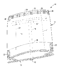
With reference now to Figure 8, therein is illustrated a further alternate
embodiment of
the present bottom and side gusseted package, designated 210. In many
respects, bottom-
gusseted package 210 is like the previously-described embodiments.
However, this
embodiment include inwardly extending side gussets 221 which do not extent the
full length of
CA 02927744 2016-04-15
WO 2015/057478 PCT/US2014/059836
-13-
the package 10, and terminate at the upper portion of bottom gusset 20. By
this arrangement,
the package 210 still exhibits the desired "self-standing" characteristics by
virtue of the manner
in which the legs of the bottom gusset can spread apart and open.
In Figure 8, the package 210 is oriented such that the rear package panel 16
is visible,
with seam 18 extending longitudinally of the package. Top seal 30 can be
formed so that the
inwardly extending side gussets 221 are generally open at the top of the
package. Side seals
22 can be provided joining the front package panel 14 to the rear package
panel 16 so that
bottom gusset 20 is closed at the opposite ends thereof As shown, the depth of
inwardly
extending side gussets can decrease from the top seal from the top seal 30 to
the side seals 22,
with the gussets terminating at the side seals 22.
From the foregoing, it will be observed that numerous modifications and
variations can
be effected without departing from the true spirit and scope of the novel
concept of the present
invention. It is to be understood that no limitation with respect to the
specific embodiments
illustrated herein is intended or should be inferred. The disclosure is
intended to cover, by the
appended claims, all such modifications as fall within the scope of the
claims.