Note: Descriptions are shown in the official language in which they were submitted.
CA 02927974 2016-04-19
WO 2015/009335
PCT/US2014/019286
-1-
IMPLEMENT INTERFACE
BACKGROUND
[0001] This
application is directed towards power machines. More particularly, this
application is directed toward operably coupling implements to power machines.
Power
machines, for the purposes of this disclosure, include any type of machine
that generates
power for the purpose of accomplishing a particular task or a variety of
tasks. One type of
power machine is a work vehicle. Work vehicles are generally self-propelled
vehicles that
have a work device, such as a lift arm (although some work vehicles can have
other work
devices) that can be manipulated to perform a work function. Some examples of
work vehicle
power machines include loaders, excavators, utility vehicles, tractors, and
trenchers, to name
a few.
[0002] Some power
machines can be operably coupled to implements that are capable of
cooperating with the power machine to perform various tasks. For example, some
loaders
have lift arms that are capable of having a wide variety of implements
operably coupled to
them, ranging from a simple bucket or blade to relatively complex implements
such as
planers and graders that have work devices capable of perfonning various
tasks. Some of
these work devices on implements are controllable by operator input devices on
the power
machines to which they are operably coupled. Many power machines of this type
are capable
of providing power and/or control signals to an operably coupled implement.
Thus, when a
particular power machine is operably coupled to an implement, a connection is
made between
one or more power and/or control signal sources on the power machine and the
implement.
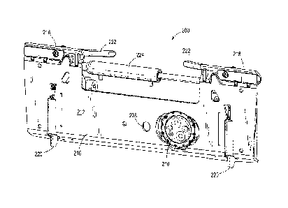
One common type of power source on such types of power machines is a hydraulic
power
source. Pressurized hydraulic fluid is selectively provided from the power
machine to the
implement once the connection is made.
[1:1003] The
discussion above is merely provided for general background information and
is not intended to be used as an aid in detet mining the scope of the
claimed subject matter.
SUMMARY
[0004] This
document discloses an interface for an implement that is to be operably
coupled to a power machine. In one embodiment, an implement carrier is
disclosed. The
implement carrier is configured to be mounted to a power machine and receive
and secure an
implement for use with the power machine. The implement carrier includes an
implement
carrier frame, a locking feature for securing an implement to the implement
carrier frame, and
- 2 -
a coupler block that is configured to be engaged with couplers on the
implement to provide
power to the implement. The coupler block has a plurality of couplers mounted
in it for
engagement with couplers on an implement and it is pivotally mounted to the
implement
carrier frame.
[0005] In another embodiment, a power machine having an implement carrier
is
disclosed. The power machine has a frame, a power source supported by the
frame, and a lift
arm pivotally mounted to the frame. The implement carrier is pivotally mounted
to the lift
arm and is configured to receive and secure an implement for use with the
power machine.
The implement carrier includes a plurality of couplers that are configured to
be engaged with
the implement to provide a power signal from the source to the implement. A
locking
mechanism is provided for securing the implement to the implement carrier. The
power
machine is further disclosed in combination with an implement.
[0006] In another embodiment, a method of interfacing an implement with a
power
machine is disclosed. The method includes providing an implement carrier on
the power
machine capable of engaging and securing the implement to the power machine.
The
implement carrier has a frame, a coupler assembly housing a plurality of
couplers that provide
a power source to the implement and a locking actuator for securing the
implement to the
implement carrier. The coupler assembly is positioned on a back side of the
frame and the
couplers being accessible from a front side of the frame. The method further
includes aligning
the implement carrier with and engaging the implement, aligning the coupler
assembly with
couplers on the implement, and actuating the locking actuator to secure the
implement to the
implement carrier.
According to an aspect of the present invention, there is provided an
implement
carrier configured to be mounted to a power machine, the implement carrier
being configured
to receive and secure an implement for use with the power machine, comprising:
an implement carrier frame;
a locking feature for securing the implement to the implement carrier frame;
and
a coupler block having a first plurality of couplers mounted therein for
engagement with a second plurality of couplers on the implement to provide a
power source
for the implement,
wherein the coupler block is pivotally mounted to the implement carrier frame
such that the coupler block freely rotates around an axis.
CA 2927974 2019-02-27
-2a-
According to another aspect of the present invention, there is provided a
power
machine, comprising:
a frame;
a power source supported by the frame;
a lift arm pivotally mounted to the frame; and
an implement carrier pivotally mounted to the lift arm, the implement carrier
being configured to receive and secure an implement for use with the power
machine, the
implement carrier including a locking mechanism for securing the implement and
a plurality
of couplers configured to be engaged with the implement to provide a power
signal from the
power source to the implement;
wherein the implement carrier is further configured so that receiving and
securing
the implement also causes the plurality of couplers on the implement carrier
to be aligned
and engaged with the implement; and
wherein the plurality of couplers freely rotates around an axis.
According to another aspect of the present invention, there is provided an
implement in combination with the power machine as described herein, the
implement
comprising:
an implement carrier interface having a locking feature engaged by the locking
mechanism and a plurality of implement couplers mounted thereon in engagement
with the
plurality of couplers on the implement carrier.
According to another aspect of the present invention, there is provided a
method
of interfacing an implement with a power machine, comprising:
providing an implement carrier on the power machine capable of engaging and
securing the implement to the power machine, the implement carrier having:
a frame with a generally flat surface for engaging the implement;
a coupler assembly housing a first plurality of couplers that provide a
power source to the implement, the coupler assembly being positioned on a back
side of the frame and the first plurality of couplers being accessible from a
front
side of the frame,
wherein the coupler assembly is pivotally mounted to the frame such
that the coupler assembly freely rotates around an axis; and
a locking mechanism for securing the implement to the implement
carrier;
CA 2927974 2019-02-27
-2b-
aligning the implement carrier with and engaging the implement;
aligning the coupler assembly with a second plurality of couplers on
the implement; and
actuating the locking mechanism to secure the implement to the
implement carrier.
According to another aspect of the present invention, there is provided a
method
of interfacing an implement with a power machine, comprising:
providing an implement carrier on the power machine configured to engage and
secure the implement to the power machine, the implement carrier having:
a frame with a surface for engaging the implement;
a coupler movably mounted to the frame that provides a power source
to the implement, the coupler being positioned on a back side of the frame and
accessible from a front side of the frame; and
a locking mechanism for securing the implement to the implement
carrier;
aligning the implement carrier with and engaging the implement;
causing the coupler mounted to the frame to align with a coupler on the
implement
positioned in front of the coupler mounted to the frame; and
actuating the locking mechanism to secure the implement to the implement
carrier.
According to another aspect of the present invention, there is provided an
implement carrier configured to be mounted to a power machine, the implement
carrier being
configured to receive and secure an implement for use with the power machine,
comprising:
an implement carrier frame configured to receive and secure an implement
thereto; and
a coupler block having at least one coupler mounted therein for engagement
with
at least one coupler on the implement to provide a power source for the
implement,
wherein the coupler block is mounted to the implement carrier frame such that
the coupler block is configured to move freely in at least one direction
relative to the
implement carrier frame.
According to another aspect of the present invention, there is provided a
power
machine, comprising:
a frame;
CA 2927974 2019-02-27
-2c-
a power source supported by the frame;
a lift arm pivotally mounted to the frame; and
an implement carrier pivotally mounted to the lift arm, the implement carrier
being configured to receive and secure an implement for use with the power
machine, the
implement carrier including a locking mechanism for securing the implement and
at least one
coupler configured to be aligned and engaged with the implement when received
and secured
to provide a power signal from the power source to the implement, and wherein
the at least
one coupler is configured to move freely relative to another portion of the
implement carrier
in response to engagement from the implement.
According to another aspect of the present invention, there is provided an
implement in combination with the power machine as described herein, the
implement
comprising:
an implement carrier interface having a locking feature engaged by the locking
mechanism and at least one implement coupler mounted thereon in engagement
with the at
least one coupler of the implement carrier.
According to another aspect of the present invention, there is provided a
method
of interfacing an implement with a power machine, comprising:
providing an implement carrier on the power machine configured to engage and
secure the implement to the power machine, the implement carrier having:
a frame with a surface for engaging the implement; and
a coupler movably mounted to the frame that provides a power source
to the implement, the coupler being positioned on a back side of the frame and
accessible from a front side of the frame; and
aligning the implement carrier with and engaging the implement, comprising
lifting the implement to allow the weight of the implement to urge the coupler
on the
implement into engagement with the coupler on the implement carrier.
According to another aspect of the present invention, there is provided an
implement carrier configured to be mounted to a power machine, the implement
carrier being
configured to receive and secure an implement for use with the power machine,
comprising:
an implement carrier frame configured to receive and secure an implement
thereto; and
a coupler block having at least one coupler mounted therein for engagement
with
at least one coupler on the implement to provide a power source for the
implement;
CA 2927974 2019-02-27
-2d-
wherein the coupler block is mounted to the implement carrier frame such that
the coupler block is configured to move relative to the implement carrier
frame;
wherein the implement carrier frame has a front side and an opposing rear side
and wherein the coupler block is pivotally mounted on the rear side of the
implement carrier
frame and the at least one coupler mounted in the coupler block is accessible
from the front
side of the implement carrier frame.
100071 This Summary and the Abstract are provided to introduce a
selection of concepts
in a simplified form that are further described below in the Detailed
Description. This
Summary is not intended to identify key features or essential features of the
claimed subject
matter, nor is it intended to be used as an aid in determining the scope of
the claimed subject
matter.
BRIEF DESCRIPTION OF THE DRAWINGS
[0008] FIG. 1 is a side elevation view of a representative power machine
of the type on
which the disclosed embodiments can be practiced.
[0009] FIG. 2 is a perspective view of the representative power machine
of FIG. 1,
showing a prior art implement carrier.
CA 2927974 2019-02-27
CA 02927974 2016-04-19
WO 2015/009335
PCT/US2014/019286
-3-
[0010] FIG. 3 is a perspective view showing a first side of an implement
carrier having a
coupler block for providing a connection between a power source on a power
machine and an
implement according to one illustrative embodiment.
[0011] FIG. 4 is a perspective view showing a second side of the implement
carrier of
FIG. 3.
[0012] FIG. 5 is a perspective view showing a first side of the coupler
block illustrated in
FIG. 3.
[0013] FIG. 6 is a perspective view showing a second side of the coupler
block illustrated
in FIG. 5.
[0014] FIG. 7 is an exploded view of the coupler block illustrated in FIG.
5.
[0015] FIG. 7A is a cross-section of a portion of the coupler block of FIG.
5.
[0016] FIG. 7B illustrates an enlarged view of the implement carrier of
FIG.3 illustrating
a coupler block carrier for carrying the coupler block of FIG. 5 according to
one illustrative
embodiment.
[0017] FIG. 7C is a cross-sectional view of the coupler block carrier of
FIG. 7B.
[0018] FIG. 8 is a schematic representation of a portion of a hydraulic
circuit of a power
machine having an implement carrier having a coupler block as shown in HG. 3
according to
one embodiment.
[0019] FIG. 8A is a schematic representation of a portion of hydraulic
circuit of a power
machine having an implement carrier having a coupler block as shown in HG. 3
according to
another embodiment.
[0020] HG. 9 is a perspective rear view of one embodiment of an implement
capable of
being coupled to an implement carrier of the type illustrated in FIG. 3.
[0021] FIG. 10 is an enlarged view of an implement carrier interface from
the implement
of FIG. 9, showing a coupler assembly in more detail.
[0022] FIG. 11 is a flowchart illustrating a method of coupling an
implement having a
coupler assembly of FIG. 10 to a power machine having an implement carrier of
FIG. 3
according to one illustrative embodiment.
[0023] FIG. 12 illustrates a coupler block for an implement carrier of a
power machine
and coupler assembly for an implement that are configured to engage and be
secured to one
another according to another illustrative embodiment.
[0024] FIG. 13 is a cross-sectional perspective view of the coupler
assembly of FIG. 12,
taken across two of the hydraulic couplers.
CA 02927974 2016-04-19
WO 2015/009335
PCT/US2014/019286
-4-
[0025] FIG. 14 is a
cross-sectional view of the coupler block of FIG. 12 aligned with the
coupler assembly of FIG. 12, the cross-section taken across two of the
couplers.
[0026] FIGs. 15-17
illustrate the coupler block and coupler assembly of FIG. 14 in
various states of engagement.
[0027] FIG. 18 is a
flowchart illustrating a method of relieving pressure in the coupler
assembly illustrated in FIGs. 14-17 according to one illustrative embodiment.
[0028] FIG. 19 is a
cross-sectional perspective view of a coupler assembly configured to
be engaged with and connected to the coupler block of FIG. 12 according to
another
illustrative embodiment, the cross section taken across two couplers and an
internal blocking
valve.
[0029] FIG. 20
illustrates a cross-sectional view of the coupler assembly of FIG. 19
aligned with the coupler block of FIG. 12.
[0030] FIGs. 21-23
illustrate the coupler block and coupler assembly of FIG. 20 in
various states of engagement.
[0031] FIG. 24 is a
flowchart illustrating a method of relieving pressure in the coupler
assembly illustrated in FIGs. 20-23 according to an illustrative embodiment.
[0032] FIG. 25 is a
cross-sectional view of a coupler assembly configured to be engaged
with and connected to the coupler of FIG. 12 according to another illustrative
embodiment,
the cross section being taken across two hydraulic couplers.
DETAILED DESCRIPTION
[0033] The concepts
disclosed in this discussion are described and illustrated with
reference to exemplary embodiments. These concepts, however, are not limited
in their
application to the details of construction and the arrangement of components
in the
illustrative embodiments and are capable of being practiced or being carried
out in various
other ways. The terminology in this document is used for the purpose of
description and
should not be regarded as limiting. Words such as "including," "comprising,"
and "having"
and variations thereof as used herein are meant to encompass the items listed
thereafter,
equivalents thereof, as well as additional items.
[0034] Inventive
concepts are set forth in embodiments discussed below. The
embodiments are directed toward power machines, implements that are designed
to be
operably coupled to power machines, and connection systems and methods for
connecting
one or more power sources on the power machine to the implement. More
particularly, the
embodiments discussed below are directed toward connection systems and methods
for
CA 02927974 2016-04-19
WO 2015/009335
PCT/US2014/019286
-5-
connecting one or more power sources on the power machine to the implement by
making a
connection through an implement carrier on the power machine. For the purposes
of this
discussion, a representative power machine on which the embodiments can be
practiced is
illustrated in FIGs. 1-2 and described below before any embodiments are
disclosed. For the
sake of brevity, only one representative power machine is discussed. However,
as mentioned
above, the embodiments below can be practiced on any of a number of power
machines,
including power machines of different types front the representative power
machine
discussed below. In particular, the embodiments disclosed below can be
practiced on power
machines having different sized and shaped implement carriers than the ones
shown in the
representative power machine.
[0035] FIG. 1 is a
side elevation view and FIG. 2 is a perspective view of a representative
power machine 100 upon which the disclosed embodiments can be employed. While
certain
features of power machine 100 are discussed here, other power machines have
other features
besides those discussed with regard to power machine 100 or variations of the
features of
power machines on which the disclosed embodiments can be practiced. The
representative
power machine 100 is a work vehicle in the form of a loader and more
particularly, a skid
steer loader. However, the concepts discussed below can be practiced on many
other types of
work vehicles such as tracked loaders, steerable wheeled loaders, including
all-wheel steer
loaders, excavators, telehandlers, walk behind loaders, trenchers, and utility
vehicles, to name
but a few examples as well as many other different types of power machines.
The power
machine 100 includes a supporting frame or main frame 102 that supports a
power source
104 such as an internal combustion engine. A power conversion system 106 is
operably
coupled to the power source 104. Power conversion system 106 illustratively
receives power
from the power source 104 and control signals from operator inputs to convert
the received
power into power signals in a form that is provided to and utilized by
functional components
of the power machine.
[0036] In some
power machines, including power machine 100, the power conversion
system 106 includes hydraulic components such as one or more hydraulic pumps,
various
actuators, and other components that are illustratively employed to receive
and selectively
provide power signals in the form of pressurized hydraulic fluid to some or
all of the
actuators used to control functional components of the power machine 100. For
example, a
control valve assembly (not separately shown) is used to selectively provide
pressurized
hydraulic fluid from a hydraulic pump to actuators such as hydraulic cylinders
that are
positioned on the power machine. Power conversion system 106 also selectively
provides
CA 02927974 2016-04-19
WO 2015/009335
PCT/US2014/019286
-6-
pressurized hydraulic fluid, to a port 134, to which an implement can be
coupled for
receiving pressurized hydraulic fluid. Other power machines upon which the
disclosed
embodiments can be practiced can employ other power conversion systems. For
example,
some power machines have power conversion systems that include electric
generators or the
like to generate electrical control signals to power electric actuators. Still
other power
machines have mechanical transmissions that act as a power conversion system,
at least so far
as a drive system is concerned.
[0037] Among the
functional components that are capable of receiving power signals
from the power conversion system 106 are tractive elements 108, illustratively
shown as
wheels, which are configured to rotatably engage a support surface to cause
the power
machine to travel. Other examples of power machines can have tracks or other
tractive
elements instead of wheels. Power machine 100 has a pair of hydraulic motors
(not shown in
FIGs. 1-2) that convert a hydraulic power signal into a rotational output. In
some power
machines, such as skid steer loaders including power machine 100, a single
hydraulic motor
is operably coupled to all of the tractive elements on one side of the power
machine. Other
power machines have, a hydraulic motor provided for each of its tractive
elements. Still other
machines have a single drive motor that is operably coupled to every driven
tractive element.
In a skid steer loader, such as power machine 100, steering is accomplished by
providing
unequal rotational outputs to the tractive element or elements on one side of
the machine as
opposed to the other side to cause the loader to skid across a support
surface. In some power
machines, steering is accomplished through other means, such as, for example,
steerable
axles.
[0038] The power
machine 100 also includes a lift aim structure 114 that is capable of
being raised and lowered with respect to the frame 102. The lift arm structure
114
illustratively includes a pair of lift arms 116 that are pivotally coupled to
the frame 102 at
pivotable joints 118 located on either side of the frame along an axis that is
perpendicular to
the frame. A pair of actuators 120 (only one is shown in FIGs. 1-2), which in
some
embodiments are hydraulic cylinders configured to receive pressurized fluid
from power
conversion system 106, are pivotally coupled to both the frame 102 and the
lift arms 116 at
pivotable joints 122 and 124, respectively on either side of the power machine
100. The
actuators 120 are sometimes referred to individually and collectively as lift
cylinders.
Extension and retraction of the actuators 120 cause the lift aiins 116 to
pivot about pivotable
joints 118 and thereby be raised and lowered along a generally vertical path.
Arrow 138
provides an indication of a general path of an end of the lift arms 116 as
they are raised and
CA 02927974 2016-04-19
WO 2015/009335
PCT/US2014/019286
-7-
lowered. The lift arm structure 114 is representative of the type of lift arm
structure that may
be coupled to the power machine 100. Other lift arm structures, with different
geometries,
components, and arrangements can be coupled to the power machine 100 or other
power
machines upon which the embodiments discussed herein can be practiced without
departing
from the scope of the present discussion.
[0039] An implement
carrier 130 is pivotally coupled to the lift arms 116 along an axis
that runs through pivotable joints 132. The implement carrier 130 is
configured to accept and
secure any one of a plurality of different types of implements thereto. By
having an
implement carrier capable of being attached to a plurality of different
implements, changing
from one implement to another can be accomplished with relative ease. For
example,
machines with implement carriers can provide an actuator between the implement
carrier and
the lift arm structure, so that removing or attaching an implement does not
involve removing
or attaching an actuator from the implement. The implement carrier 130
provides a mounting
structure for easily attaching an implement to the lift arm (or other portion
of a power
machine) that a lift arm structure without an implement carrier does not have.
[0040] One or more
actuators such as hydraulic cylinders 136 are pivotally coupled to the
implement carrier 130 and the lift aim structure 114 to cause the implement
carrier 130 to
rotate under power about an axis that extends through the pivotable joint 132
in an arc
approximated by arrow 128 in response to operator input. In some embodiments,
the one or
more actuators pivotally coupled to the implement carrier and the lift arm
assembly are
hydraulic cylinders capable of receiving pressurized hydraulic fluid from the
power
conversion system 106. The one or more hydraulic cylinders 136 are sometimes
referred to as
tilt cylinders. As mentioned above, the implement carrier 130 is configured to
accept and
secure any one of a number of different implements to the power machine 100 as
may be
desired to accomplish a particular work task.
[0041] Power
machine 100 provides a source, accessible at port 134 mentioned above, of
power and control signals that is made available for coupling to an implement
to control
various functions on such an implement, in response to operator inputs. In one
embodiment,
port 134 includes hydraulic couplers that are connectable to an implement for
providing
power signals in the form of pressurized fluid provided by the power
conversion system 106
for use by the implement. Alternatively or in addition, port 134 includes
electrical connectors
that can provide power signals and control signals to the implement to control
and enable
actuators of the type described above to control operation of functional
components on the
implement.
CA 02927974 2016-04-19
WO 2015/009335
PCT/US2014/019286
-8-
[0042] Power
machine 100 also illustratively includes a cab 140 that is supported by the
frame 102 and defines, at least in part, an operator compartment 142. Operator
compartment
142 typically includes an operator seat (not shown) and operator input devices
(not shown)
and display devices (not shown) accessible and viewable from a sitting
position in the seat.
When an operator is seated properly within the operator compartment 142, the
operator can
manipulate operator input devices to control such functions as driving the
power machine
100, raising and lowering the lift arm structure 114, rotating the implement
carrier 130 about
the lift arm structure 114 and make power and control signals available to an
implement via
the sources available at port 134. An electronic controller 150 is provided
for receiving inputs
from operator input devices and providing control signals to functional
devices on the power
machine 100. The electronic controller 150 shown in FIG. 1 can be any form of
electronic
controller or controllers capable of processing inputs and providing control
signals. While an
electronic controller 150 is shown in FIG. 1, some power machines upon which
the
embodiments described below can be practiced may not include any sort of
electronic
controller.
[0043] As discussed
above, the implement carrier 130 is capable of accepting and
securing any of a number of different implements for use to accomplish various
tasks. The
implement carrier 130 and implements capable of being secured to the implement
carrier 130
provide for flexibility of use of power machine 100, thereby allowing an
operator to perform
many different tasks with the same power machine. Implement carriers of this
type are
generally known and an example of an implement carrier for a loader is shown
in U.S. Patent
3,672,521 of Bauer et al. and an example of an implement carrier for an
excavator is shown
in U.S. Patent 5,974,706 of Kaczmarski et al. Because the implement carrier
130 is designed
to accept and secure different implements by engaging attachment features
(described below),
implements can be attached to and removed from the power machine quickly and
without the
use of tools. In certain jobs, an operator may repeatedly change implements
(i.e., remove one
implement and attach another) during a given work event to perform various
tasks.
[0044] One aspect
of this disclosure is directed toward connection systems and methods
for connecting one or more power sources on the power machine to an implement
by making
a connection through an implement carrier on the power machine. FIGs. 3-4
illustrate one
embodiment of an implement carrier 200 that is advantageously capable of
providing a
connection feature that provides a source of pressurized hydraulic fluid to an
implement that
is coupled to the implement carrier. The implement carrier 200 is of the type
that can be
provided on a power machine such as power machine 100 (thereby replacing the
implement
CA 02927974 2016-04-19
WO 2015/009335
PCT/US2014/019286
-9-
carrier 130 illustrated in FIGs. 1-2). Implement carrier 200 includes a frame
202 with a first
side 212 (illustrated in FIG. 3) and an opposing second side 214 (illustrated
in FIG. 4). For
the purposes of this discussion, the first side 212 can be referred to as a
front side and the
second side 214 can be referred to as a rear side. The first or front side 212
is oriented to
generally face and abut an implement when the implement is attached to the
implement
carrier 200. When the implement carrier 200 is attached to a power machine,
the second or
rear side 214 is generally facing the power machine to which the implement
carrier is
attached, although as described above with respect to FIGs. 1-2, an implement
carrier can
pivot with respect to an attachment point on the a power machine so the second
or rear side
214 may not always be facing the power machine. The frame 202 has one or more
engagement features 218 that are capable of engaging an implement during the
attachment
process and one or more locking features 220 that lock the implement onto the
implement
carrier. In the example embodiment shown in FIGs. 3-4, the engagement features
218 are a
pair of forward extending edges on a top of the frame 202 and the locking
features 220 are a
pair of wedges capable of being inserted into locking features on the
implement on a bottom
side of the frame. Referring briefly to FIGs. 3 and 9, during the process of
attaching
implement 300 to the implement carrier 200, the engagement features 218 of the
implement
carrier 200 engage with complementary engagement features 318 on an implement
carrier
interface 302 of implement 300. The implement 300 then pivots about an
engagement axis
between the engagement features 218 and the engagement features 318 on the
respective
implement carrier 200 and the implement 300 such that the engagement features
218 and 318
act as a sort of hinge. This pivoting occurs when the implement carrier is
rotated hack toward
the lift arm and/or the lift arm is raised, causing the implement to be lifted
so that the weight
of the implement pivots the implement into position when the engagement
features 218 and
318 are properly engaged. Other implement carriers can have various other
types of
engagement and locking features or just locking features. The frame 202 of
implement carrier
200, being the type that can be used with power machine 100, has a main
portion 216 that has
a generally flat surface against which an interface portion of an implement
can abut when
connected to the implement carrier.
[0045] The locking
features or wedges 220 can be manually operated by levers 222,
which are rotatable to raise and lower the wedges 220. In addition, an
actuator 224 is
provided that can be operated to raise and lower the wedges in response to an
operator input.
Actuator 224 in the embodiment shown is a hydraulic cylinder and will be
discussed as such
in more detail below. In other embodiments, actuator 224 can be any suitable
actuator, linear
CA 02927974 2016-04-19
WO 2015/009335
PCT/US2014/019286
-10-
or otherwise, that is capable of manipulating the locking features 220 into
and out of a locked
position (i.e. that is capable of raising and lowering the locking wedges of
this embodiment).
The implement coupler 200 also includes a coupler block or assembly 210
mounted to the
frame 202. The coupler block 210 houses a plurality of couplers that are
configured to be
connected to an implement to provide a power source. The couplers of coupler
assembly 210
include a plurality of hydraulic conduits that are capable of providing
pressurized hydraulic
fluid to an implement that is being carried by the implement carrier 200, with
the connection
of the coupler block 210 to a mating connection device on an implement being
made as part
of the mounting of such an implement onto the implement carrier 200. In other
embodiments,
couplers in a coupler assembly need not be of the type that provide
pressurized hydraulic
fluid or be limited to couplers of the type that provide pressurized hydraulic
fluid. For
example, other types of couplers that might be included in such a coupler
assembly would be
electrical couplers. Pressurized hydraulic fluid is provided from a power
source on the power
machine to the actuator 224 and the coupler assembly 210 via conduits such as
hydraulic
hoses and/or tubelines, which are not shown in FIGs. 3-4 for clarity's sake.
The implement
carrier 200 also includes an alignment feature 238 in the form of an aperture
is provided in
the main portion 216 of the frame 202 that can assist with alignment of an
implement with
the implement carrier during the implement mounting process by engaging with a
corresponding alignment feature on certain implements to be mounted on the
implement
during the implement mounting process. Some implements may not have a
corresponding
alignment feature and some embodiments of implement carriers likewise may not
have
alignment features such as alignment feature 238, but in instances where both
alignment
features are provided, the alignment of implement and implement carrier is
improved and
more particularly, the alignment of coupler block 210 and corresponding
couplers on the
implement is improved.
[0046] FIGs. 5-6
illustrate the coupler block 210 shown in FIGs. 3-4 in more detail.
Coupler block 210 is one embodiment of a coupler assembly that can be
incorporated into
implement carrier 200. Other embodiments of a coupler assembly need not
include some of
the features described with coupler block 210. At its most basic, an
embodiment of a coupler
block that can be incorporated into implement carrier 200 includes a mechanism
for holding
couplers for mating with couplers on an implement. The coupler block 210 of
FIG. 5 shows a
first side or face 215, which is capable of interfacing with couplers on an
implement and FIG.
6 shows a second side 225 that opposes the first side 215. The coupler block
210 includes a
housing 230 with a pair of mounting features 232 and 234 shown in this
embodiment as
CA 02927974 2016-04-19
WO 2015/009335
PCT/US2014/019286
-11-
including a pair of trunnions that are mountable to the implement carrier
frame 202 to allow
the coupler block 210 to pivot about an axis 236 that extends through the
mounting features
232 and 234. Because the coupler block 210 is capable of pivoting with respect
to the frame
202, the coupler block can be pivoted to align with couplers on an implement
that is attached
to the implement carrier. This pivoting feature allows the coupler block 210
to accommodate
variations from one implement to the next and/or accommodate minor
misalignment when
making connection with a particular implement. As discussed below, because of
the arcuate
movement of the implement with respect to the implement carrier 200 during the
connection
process, there will virtually always be alignment issues for which the
pivoting coupler block
accommodates. Coupler block 210 is of a generally cylindrical shape, but can
take on other
shapes as shown in succeeding embodiments discussed below without departing
from the
scope of this disclosure.
[0047] The coupler
block 210 has a plurality of couplers 240, 242, and 244 that are
configured to mate with couplers on an implement on first ends of each of the
couplers (the
couplers being oriented so that the first ends of the couplers 240, 242, and
244 are positioned
on the first face 215) to provide a power source in the form of pressurized
hydraulic fluid to
the implement. The couplers 240, 242, and 244 are capable of being coupled to
conduits on a
power machine on the second side 225. The couplers 240, 242, and 244 are shown
generically in FIGs. 5 and 6 and can be selected from any couplers that will
couple with
couplers provided on implements of the type configured to be engaged with
coupler block
210 to provide hydraulic fluid to the implement. One example of a type of
coupler that can be
employed in coupler block 210 and corresponding implements is a so-called
flush face
coupler. In the embodiment shown, first and second couplers 240 and 242
provide for a
source and return line to and from the implement, allowing for flow of the
pressurized fluid
to the implement in two different directions. That is, either of the couplers
240 and 242 can
be the source line with the other being the return line, depending on how
hydraulic fluid is
provided from the source on a power machine to which the coupler block 210 is
mounted or
depending on an application, each of the couplers can be either a source or
return on the same
power machine, that is, fluid can be provided in either of two directions, as
is stated above.
Coupler 244 provides a connection for so-called case drain line, which
provides an additional
return line from an implement. The description of the couplers 240, 242, and
244 is provided
here for illustrative purposes. In various embodiments, any number of couplers
can be
provided in a coupler block such as the one illustrated in FIGs. 5-6 for the
purposes of
providing hydraulic fluid to and receiving hydraulic fluid from an implement
in any
CA 02927974 2016-04-19
WO 2015/009335
PCT/US2014/019286
-12-
configuration or direction. The specific description of the couplers shown in
FIGs. 5 and 6 is
not intended to limit the concepts set forth herein to that particular
selection and arrangement
of couplers. Various embodiments can include different types of couplers. In
addition, the
selected couplers can be arranged in various ways without departing from the
scope of the
discussion. For example, a mating pair of couplers are often referred to as
including a male
coupler and a female coupler. In various embodiments, a coupler block or
coupler assembly
can have either male or female couplers, or a combination of both. A pair of
locating features
246 and 248 are formed into the first face 215. The locating features 246 and
248 are
apertures capable of receiving locating protrusions on an implement. Any
number and type of
locating features on a coupler block can be employed.
[0048] In the
embodiment shown in FIGs. 5-6, the coupler block 210 includes a piston
250 mounted within the housing 230. Other embodiments of the coupler block 210
may not
have a piston of the type shown in FIGs. 5-6. The piston 250 provides a way to
extend the
couplers 240, 242, and 244, which are mounted in the piston 250. The piston
250 is capable
of being moved relative to the housing 230 along an axis 252 from a fully
retracted position,
in which the piston does not extend beyond a forward edge 254 of the housing
230, to a fully
extended position, in which the piston does extend beyond the forward edge
254. When the
piston 250 is extended, the couplers 240, 242, and 244 are also extended as
they are fixed
within the piston in such a way that they move with the piston. By providing
an extending
member such as piston 250, the coupler block 210 is advantageously capable of
providing a
better engagement with an implement that is mounted to an implement carrier
and is
configured to be engaged with coupler block 210. Returning briefly to FIG. 3,
because some
implements may not be configured to engage with coupler block 210 (for
example, some
simple implements such as buckets do not require a source of hydraulic fluid
to operate
properly and other prior art implements are not configured to engage coupler
block 210, but
instead are configured to connect to a hydraulic source at port 134 shown in
FIGs. 1 and 2,
for example), having a coupler block with a piston that is capable of
extending and retracting
within its housing will allow the coupler block to be retracted behind the
generally flat
surface of the main portion 216 when such an implement is mounted on the
implement
carrier. In some embodiments, however, the coupler block is recessed from the
flat surface of
the main portion 216 such that even when the piston is fully extended, the
piston is merely
flush with, or even slightly recessed from the flat surface of the main
portion 216. As
mentioned above, other embodiments of the coupler block do not have a piston
and are thus
positioned flush with, or slightly recessed from the flat surface of the main
portion 216. The
CA 02927974 2016-04-19
WO 2015/009335
PCT/US2014/019286
-13-
position of the piston 250 is controlled by providing and evacuating
pressurized hydraulic
fluid into the housing 230. In the embodiment shown in FIGs. 5-6, a port 256
is provided that
extends into the housing 230 for providing a path to allow the entry and exit
of hydraulic
fluid into and out of the housing 230. In other embodiments, a port can be
provided in other
locations (for example, through mounting feature 232 or 234) to allow
pressurized hydraulic
fluid to enter into and exit out of housing 230 or piston 250. In still other
embodiments, a
piston such as piston 250 may be extended and/or retracted with other
actuation schemes and
apparatuses, including, for example an electrical actuator, a spring
mechanism, and
pneumatic actuators, to name a few.
[0049] FIG. 7
illustrates an exploded view of the coupler block 210. The mounting
features 232 and 234 each include a post 260 and 262, respectively, that
extends laterally
from the housing and a bearing or bushing 264 and 266, respectively, held on
the respective
posts by fasteners 268 and 270, which are shown to be in the form of snap
rings. Other
embodiments can have different types of mounting features, different fasteners
or fastening
arrangements. A fitting 272 is inserted into port 256. Fitting 272 is of the
type that can be
coupled to a conduit on the power machine.
[0050] The piston
250 fits into the housing 230 and a cap 274 engages the housing 230 to
hold the piston 250 therein. The cap 274 includes apertures for engaging an
internal feature
285 in housing 230 to properly index the internal feature and prevent rotation
of the piston
250 within the housing. In other embodiments, other anti-rotation features can
be used. Seals
280 and 282 seal the piston 250 against the cap 274 and the housing 230 to
prevent the
intrusion of foreign material into the housing and seal 284 is inserted into a
groove 286,
which engages an exterior surface of the housing 230 and an interior surface
of the cap 274.
FIG. 7A illustrates a cross-sectional view of a portion of the coupler block
210. Seal 284 is
shown seated into groove 286 and seals 280 and 282 are shown positioned
between the piston
250 and the cap 274 and housing 230, respectively. Seals 280 and 282 are
defoimed to fit and
seal against the piston 250, with their non-defoimed or free shape shown in
outline against
piston 250 in FIG. 7A. Seal 290 is positioned in a groove 292 in the piston
250 and seal 294
is positioned in a groove 296 in the housing 230 to seal the pressurized
hydraulic fluid that is
provided via port 256 into housing 230 to urge the piston 250 out of the
housing (i.e. the
housing with the cap 274 attached thereto as shown in FIG. 7A. The piston 250
is, in one
embodiment, not biased into any one position but can be retracted when a force
is applied to
the piston on the first surface 215 of the coupler block 210, even if
hydraulic fluid is being
provided into the housing 230, provided the force applied to the first surface
215 is greater
CA 02927974 2016-04-19
WO 2015/009335
PCT/US2014/019286
-14-
than the force applied by the hydraulic fluid provided into the housing 230
for the purposes of
urging the piston 250 out of the housing.
[0051] As discussed
above, the coupler block 210 is pivotally mounted into the
implement carrier 200. FIGs. 7B and 7C illustrate a portion of implement
carrier 200 showing
a carrier 205 to which the coupler block 210 is pivotally mounted. The carrier
205 includes a
fixed portion or ring 207 that is secured to the main portion 216 of the
implement carrier 200.
In the embodiment shown, the main portion 216 includes a front plate 217 that
forms some or
all of the front side 212 of the implement carrier 200. An angled back plate
219 is secured to
the front plate 217 such as by welding and the ring 207 of the carrier 205 is
secured to the
angled back plate 219 such as by welding. The ring 207 can also be fixed to
the front plate
217 by welding. The front plate also includes an angled engagement surface
231, which is
configured to engage a complementary surface on an implement to apply a
retaining force on
the implement when the implement is secured to the implement carrier 200. The
ring 207 has
a pair of notches 221 formed into an outside wall 223, the notches being sized
to accept a
portion of the mounting features 232 and 234 (shown in FIG. 5) of the coupler
block 210.
During assembly, the coupler block 210 is placed into position adjacent the
fixed portion 207
of the carrier 205 and is pivotally secured by the fixed portion and a
removable cover portion
209 of the carrier. The removable cover portion 209 of the carrier 205 is
secured to the fixed
portion 207 with fasteners 211. The removable cover portion has notches 227
that are aligned
with notches 221 to engage and hold the coupler block in place. Different
embodiments can
have a coupler block carrier with different features from those of carrier
205. For example,
other carriers can have a removable cover that is made of a single piece as
opposed to the
plurality of pieces shown in FIG. 7B. As another example, the coupler block
can be inserted
into a carrier and the entire carrier can be affixed with fasteners to the
implement carrier,
rather than having a fixed portion that is welded to the implement carrier.
[0052] FIG. 8
schematically illustrates a portion of a hydraulic circuit 291 for use in a
power machine such as power machine 100 for providing pressurized hydraulic
fluid to
coupler block 210 on implement carrier 200. The hydraulic circuit 291 includes
a source 271
of pressurized hydraulic fluid that is capable of being selectively supplied
via a first output
267 or a second output 269 such that when pressurized hydraulic fluid is
provided via one of
the first output and the second output, the source is capable of receiving
returned fluid via the
other of the first output and the second output. The source 271 can include a
bi-directional
pump that is controlled to selectively provide pressurized hydraulic fluid or
alternatively, a
pump that provides pressurized hydraulic fluid to a control valve, which in
turn selectively
CA 02927974 2016-04-19
WO 2015/009335
PCT/US2014/019286
-15-
provides hydraulic fluid in response to operator input to either one of the
first and second
outputs 267 and 269. A path is provided from the first output 267 via a
conduit 273 to the
coupler 240 and a path is provided from the second output 269 via a conduit
275 to coupler
242. In addition, the first and second outputs 267 and 269 are in fluid
communication with a
shuttle valve 277 as inputs thereto.
[0053] An output of
the shuttle valve 277 is provided as an input to a coupler block
control valve 279, which is capable of selectively providing pressurized
hydraulic fluid to and
evacuating pressurized hydraulic fluid from coupler block 210. Coupler block
control valve
279 as shown in FIG. 8 is a two-position valve with a first position 281
providing a path from
coupler block 210 to a low pressure reservoir 287. The coupler block control
valve 279 is
biased to the first position 281 in this embodiment, although in other
embodiments that need
not be the case. When the coupler block control valve 279 is in a second
position 283, the
output of the shuttle valve 277 is in communication with coupler block 210 and
more
specifically with port 256 of coupler block 210. When coupler block control
valve 279 is in
the second position 283 and the source 271 is providing pressurized hydraulic
fluid to one of
the first and second outputs 267 and 269, the pressurized hydraulic fluid is
also provided via
the second position 283 to port 256 of control block 210, thereby urging
piston 250 out of the
housing. When the source 271 is not providing pressurized hydraulic fluid to
one of the first
and second outputs 267 and 269 and the coupler block control valve 279 is in
the second
position 283, any pressure that may have been provided to port 256 when the
shuttle valve
277 is closed will be present to piston 250.
[0054] An actuator
285 is provided to control the position of the valve 279. Actuator 285,
when actuated, overcomes a biasing member 289 to move the valve from the first
position
281 to the second position 283. Actuator 285 is an electrically actuated
solenoid, although
any suitable actuator can be used. Actuator 285 is actuated in response to
operator input. In
one embodiment, the actuator 285 is actuated in response to actuation of an
operator input
that initiates an auxiliary hydraulics mode, that is, a mode that allows for
providing hydraulic
fluid to an implement that is operably coupled to the power machine. In other
embodiments,
actuator 285 can be actuated in response to other operator inputs.
[0055] FIG. 8A
illustrates schematically illustrates an alternative embodiment of a
portion of a hydraulic circuit 291A form providing pressurized hydraulic fluid
to coupler
block 210 on implement carrier 200. A power source 271A provides a source of
pressurized
hydraulic fluid via an output 267A, which is provided to a coupler block
control valve 279A.
The power source 271A is, in one embodiment, a constant volume pump that
provides fluid
CA 02927974 2016-04-19
WO 2015/009335
PCT/US2014/019286
-16-
in a single direction, thereby eliminating the need for a shuttle valve of the
type shown in
FIG. 8 to select an input to the coupler block control valve 279A. A check
valve 263A is
provided between the source 271A and the coupler block control valve 279A. The
coupler
block control valve 279A is similar to the coupler block control valve 279 and
is used to
selectively provide and evacuate fluid to block 210 for controlling the
introduction and
evacuation of pressurized fluid be to piston 230. Coupler block control valve
279A has a first
position 281A that provides a path from coupler block 210 to a low pressure
reservoir 287.
The coupler block control valve 279A is biased to the first position 281 via
biasing member
289A. When the coupler block control valve 279A is in a second position 283A,
the output
267A of the source 271A is in communication with coupler block 210 and more
specifically
with port 256 of coupler block 210, thereby urging piston 250 out of the
housing.
[0056] Actuator
285A is provided to control the position of the valve 279A. Actuator
285A, when actuated, overcomes biasing member 289A to move the valve from the
first
position 281A to the second position 283A. Actuator 285A is an electrically
actuated
solenoid, although any suitable actuator can be used. Actuator 285A is
actuated in response to
operator input. In one embodiment, the actuator 285A is actuated in response
to actuation of
an operator input that initiates an auxiliary hydraulics mode, that is, a mode
that allows for
providing hydraulic fluid to an implement that is operably coupled to the
power machine. In
other embodiments, actuator 285 can be actuated in response to other operator
inputs.
[0057] FIG. 9
illustrates an implement 300 of the type that is configured to be mounted
onto implement carrier 200 and more particularly is configured to be coupled
with coupler
block 210 according to one illustrative embodiment. Implements of this type,
including
implement 300 include an implement carrier interface 302 and a tool portion
304. The
implement carrier 302 interface includes complementary engagement features 318
and
locking features 320 that are configured to engage the engagement features 218
and 220
(shown in FIG. 3) on implement carrier 200 to secure the implement 300 to the
implement
carrier and a complementary angled engagement surface 331 that is configured
to engage the
angled engagement surface 231 when the implement 300 is coupled to the
implement carrier
200. The complementary engagement features 218 and 318 and 231 and 331 and the
locking
features 220 and 320 ensure that implement 300 is secured to an implement
carrier such as
implement carrier 200 in substantially the same position. During the
attachment process, the
implement 300 pivots about the axis of engagement of complementary features
218 and 318
so that the implement 300 travels along an arcuate path about the axis of
engagement to
attach the implement to the implement carrier. Because various power machines
have an
CA 02927974 2016-04-19
WO 2015/009335
PCT/US2014/019286
-17-
implement carrier substantially similar to implement carrier 200 and various
implements have
implement interfaces that are substantially similar to implement interfaces
302, a single
implement can be secured to a variety of different power machines and a
variety of different
implements (including a variety of different types of implements) can be
attached to a single
power machine. However, manufacturing variances and component wear over time
can result
in a less than identical lineup between a given implement carrier and a given
implement
interface. Because it is important to have precise alignment of the coupler
block 210 and
couplers on the implement, alignment features are provided as are discussed
above and in
more detail below.
[0058] The tool
portion 304 includes a blade 306 that is mounted to a frame 308 at a
pivotal mount 310. An actuator in the form of a hydraulic cylinder 312 is
provided to pivot
the blade 306 in response to operator inputs that are actuated to cause a
power machine to
which the implement is attached to provide pressurized hydraulic fluid to the
implement (via
a coupler block 210 as shown above). Different implements will have different
tool portions
and the implement 300 shown is for illustrative purposes only, with the
understanding that
many other types of tools can incorporate the concepts related to coupling of
a power source
through an implement carrier to an implement.
[0059] FIG. 10
shows an enlarged view of implement carrier interface 302. Implement
interface includes a generally flat surface 325 with a coupler assembly 330
that is configured
to engage coupler block 210. Coupler assembly 330 includes couplers 340, 342,
and 344,
each of which is configured to engage with couplers 240, 242. and 244,
respectively. A pair
of locating features 346 and 348 are provided that are configured to engage
with locating
features 246 and 248. In addition, a locating feature 338 is capable of
engaging locating
feature 238 in the main portion 216 of the implement carrier 200.
[0060] FIG. 11
illustrates a method 400 of securing an implement having an implement
carrier interface such as implement carrier interface 302 described above to
an implement
carrier 200 according to one illustrative embodiment. The method 400 is
described with
reference to features of the implement carrier 200 and the implement carrier
interface 302
illustrated in FIGs. 3-10 and discussed above. At block 402 of the method, a
power machine
having an implement carrier 200 is aligned and engaged with an implement
carrier interface
302. Aligning and engaging the implement carrier 200 can include rotating the
implement
carrier about pivoting joint 132 so that engagement features 218 are aligned
with engagement
features 318 and positioning locking features 220 in an unlocked position.
These particular
details are relevant to the implement carrier described above. Implement
carriers having other
CA 02927974 2016-04-19
WO 2015/009335
PCT/US2014/019286
-18-
types of engagement and/or locking features can require that other steps be
taken to align and
engage an implement carrier with an implement carrier interface. In addition,
implement
carrier 200 is capable of securing implements that do not have couplers
capable of interfacing
with coupler block 210. The method 400 is directed specifically at securing an
implement
such as implement 300 that does have such couplers to the implement carrier
200.
[0061] At block
404, the method further includes aligning coupler block 210 on the
implement carrier 200 with couplers on the implement. This alignment may occur
simultaneously with the engagement of the implement carrier with the implement
carrier
interface. However, because the implement 300 is rotating about the axis of
engagement
formed by the engagement of the engagement features on each of the implement
carrier 200
and the implement, during the alignment process, the couplers on the implement
are not in
alignment with the coupler block 210. That is, if the coupler block 210 is
oriented such that
the front face 215 is parallel with first side or face 212, the couplers on
the implement 300
will not be aligned with the couplers in the coupler block (i.e. the couplers
on the implement
will not be positioned along the axis 252. As described above, the coupler
block 210 is
capable of rotating on its mounting features 232 and 234 to accommodate the
lack of linear
alignment because of the arcuate travel path of the implement. The alignment
is thus a sort of
clamshell alignment process, with the coupler block 210 pivoting to align with
the implement
couplers (i.e. rotating so that axis 252 is in alignment with the couplers on
the implement
300) as the implement 300 approaches the implement carrier. Advantageously,
the weight of
the implement 300 itself facilitates the alignment and urges the engagement of
the coupler
block 210 with the couplers on the implement 300. Thus, the implement coupler
block 210
and the couplers on the implement can be aligned and engaged without the use
of any
additional actuators to make the connection. While the embodiments above
disclose a
pivoting coupler block 210 and rigid or stationary couplers on the implement,
in alternate
embodiments, the arrangement of the coupler block and rigidly mounted couplers
can be
reversed, with a pivoting coupler block being mounted to the implement and
with rigidly
mounted couplers being mounted on the implement carrier.
[0062] Alignment of
the coupler block 210 and the couplers on the implement 300
includes engagement of the locating feature 338 on the implement carrier
interface 302 with
the locating feature 238 on the implement carrier 200 and engagement of the
locating features
346 and 348 with the locating features 246 and 248. In the embodiments shown
above, the
locating features 338, 346, and 348 are protruding pins that engage locating
features 238,
246, and 248, which are apertures. Because, as is described above, the
implement carrier 200
CA 02927974 2016-04-19
WO 2015/009335
PCT/US2014/019286
-19-
is configured to be secured not only to implements that are configured to
engage with coupler
block 210, but also with implements that are not configured to engage with
coupler block
210, it is advantageous that locating features 238, 246, and 248 are such that
they do not
extend beyond the first face 215. The locating feature 338, in one embodiment,
is longer than
the locating features 346 and 348. Thus, locating feature 338 engages with the
locating
feature 238 before the locating features 346 and 348 engage with locating
features 246 and
248. The interaction of locating features 238 and 338 provides a relatively
rough alignment
and will facilitate the location of coupler 210 with respect to coupler 330,
with the subsequent
interaction of the locating features 246 and 248 with locating features 346
and 348 providing
a final alignment. When all of the locating features are engaged, the couplers
240, 242, and
244 are aligned with the couplers 340, 342, and 344.
[0063] At block
406, the implement 300 is secured to the implement carrier 200. 'Ibis is
accomplished by engaging the locking features or wedges 220 on the implement
carrier 200
with the locking features 320 on the implement 300. When the implement 300 is
secured to
the implement carrier 200, the implement carrier 200 applies a holding force
against the
engagement features 318 and the complementary angled engagement surface 331 to
hold the
implement 300 on the implement carrier, with the wedges 220 engaging the
locking features
320 to ensure that the implement 300 remains in place. When the implement 300
is secured to
the implement carrier 200, the couplers 240, 242, and 244 in the coupler block
210 are
aligned with the couplers 340, 342, and 344 and in the process of securing the
implement
carrier 200, these aligned couplers are coupled together. Because the couplers
are coupled
together as part of securing the implement to the implement carrier, on power
machines that
employ an actuator such as actuator 224 to secure the implement to the
implement carrier, an
operator will be able to secure the implement to the implement carrier and
simultaneously
couple the couplers, all without leaving the operator compartment. However,
due to
variations in manufacturing from one implement to another or one implement
earlier to
another or in wear over time during operation, the couplers 240, 242 and 244
may not extend
far enough to be fully coupled to the couplers 340, 342, and 344. Thus, at
block 408, the
method provides for extending the piston 250 forward toward the couplers 340,
342, and 344,
thereby advantageously providing a structure and method for providing
alignment in a fore
and aft direction relative to coupler block 210. Extension of the piston 250
is accomplished in
response to an operator input. This input can be the same input used to signal
an intention to
cause actuator 224 to engage the locking features or wedges 220 with locking
features 320 or
a separate input device can be provided to receive a signal to extend the
piston 250. In
CA 02927974 2016-04-19
WO 2015/009335
PCT/US2014/019286
-20-
embodiments where a piston such as piston 250 is not provided in the coupler
block, an
attachment method would not include this step.
[0064] Implements
such as implement 300 that have hydraulic actuators, such as
cylinders, motors, and the like that receive pressurized hydraulic fluid from
a power machine
typically have couplers for connection to the power machine that prevent
hydraulic fluid from
escaping from hydraulic lines on the implement when the implement is not
connected to a
power machine. The couplers thus operate as check valves that block flow out
of the
implement when the implement is not coupled to a power machine. While this
advantageously prevents hydraulic fluid from leaking out of the implement,
when an
implement is disconnected, residual pressure (or pressure buildup, for example
as the result
of temperature changes between the time when an implement is disconnected and
reconnected) in the implement can make connection to a power machine
difficult, because
enough force has to be applied to the couplers to overcome the pressure in the
hydraulic
conduits on the implement. FIG. 12 illustrates another embodiment of a coupler
assembly
600 for use on an implement such as implement 300 to house couplers and that
provide
additional features for pressure relief when the implement is not coupled to a
power machine.
Coupler assembly 600 is shown in FIG. 12 positioned adjacent to a coupler
block 500.
Coupler block 500 illustrates another embodiment of a coupler block of the
type that can be
integrated into an implement carrier such as implement carrier 200. Coupler
block 500 is
shaped somewhat differently than coupler block 210 described above, and thus
would require
a differently shaped carrier than carrier 205. In addition, coupler block 500
does not include
the piston arrangement (i.e. piston 250) of coupler block 210. Thus, the
piston 250 and its
functions are not necessarily included in every embodiment, as shown here,
although coupler
blocks with a piston arrangement similar to piston 250 can be used to engage
the coupler
assembly 600 without departing from the scope of the disclosure. Coupler block
500 does
include a housing 530, couplers 540, 542, and 544 as well as a pair of
trunnion mounting
features (only one of which, 532, is shown in FIG. 12). The couplers 540 and
544 shown in
cross-section in FIGs. 13-17 are shown to each have a stem (550 and 551,
respectively). Any
couplers capable of interfacing with couplers 640, 642, and 644 can be used in
coupler block
500 and such couplers will necessarily have internal features not shown in any
of FIGs. 13-
17. For example, stems 550 and 551 necessarily will include features to
position them within
their respective couplers and/or provide a biasing force as necessary.
[0065] Coupler
assembly 600 includes a housing 630, with couplers 640, 642, and 644
mounted therein. Coupler assembly 600 is configured to be rigidly mounted on
an implement
CA 02927974 2016-04-19
WO 2015/009335
PCT/US2014/019286
-21-
interface such as implement interface 302 so that the couplers in the coupler
assembly can be
positioned and sized to engage with couplers 540, 542, and 544 on coupler
block 500.
Locating features 646 and 648 are likewise sized and positioned to engage with
locating
features on coupler block 500 (not shown in FIG. 12). In alternate
embodiments, coupler
assembly 600 can be pivotally mounted to an implement interface. A debris
shield 602 is
attached to the housing 630 to deflect material that might fall between the
coupler assembly
600 and the coupler block 500 when they are mated.
[0066] FIG. 13
illustrates a cross section of coupler assembly 600 taken across couplers
640 and 644. Coupler 642 is substantially similar to coupler 640 and is not
shown in cross-
section for simplicity's sake. Coupler 640 is inserted into a cavity 650 in
coupler assembly
600 and fixed in the cavity such as by a threaded engagement. As shown in FIG.
13, a groove
652 is formed into the coupler 640 for carrying a seal (not shown) to seal the
coupler 640 in
the coupler assembly 600. Coupler 640 is configured to engage with a mating
coupler (such
as coupler 540 in coupler block 500) to provide a fluid flow path between a
power machine
and hydraulic components on an implement. The coupler assembly 600 includes a
port 656
(shown in FIG. 14) that provides a communication path from the cavity 650 with
a hydraulic
circuit on the implement. In addition, coupler assembly 600 has a fluid relief
path 654 that is
selectively in communication with cavity 650. The fluid relief path 654, as
discussed in more
detail below, provides additional volume to hold pressurized fluid when the
implement is not
connected to a power machine, thereby reducing the pressure of fluid in the
implement when
the implement is not attached to a power machine.
[0067] Coupler 640
includes a body 660 and a valve member 662, which is movable
between a closed position as shown in FIG. 13 and an open position. A seal
(not shown) is
positioned with in a groove 663 in the body 660 to seal the valve member 662
against the
body. In the closed position, hydraulic fluid is generally unable to enter or
exit the coupler
assembly 600 through coupler 640. A biasing member 664 biases the valve member
662 to
the closed position. When the valve member 662 is in the open position,
hydraulic fluid is
capable of entering or exiting the coupler assembly 600 through coupler 640.
Coupler 644
likewise has a valve member 666 and a biasing member 668. Valve member 666 is
also
shown in a closed position in FIG. 13, with biasing member 668 urging the
valve member
666 into the closed position.
[0068] FIG. 14
illustrates a cross-section of coupler assembly 600 along with a cross
section of coupler block 500 positioned adjacent and aligned with coupler
assembly 600, but
not yet engaged with coupler assembly 600. FIG. 14 provides a better view of
fluid relief path
CA 02927974 2016-04-19
WO 2015/009335
PCT/US2014/019286
-92-
654 and the engagement between the fluid relief path and cavity 650. Fluid
relief path 654
includes an opening 655 into which a plunger portion 670 of the valve member
662 enters
when the valve member 662 moves from the closed position to the open position.
A sealing
member 672 is fitted over the plunger 670 and is shaped to engage and seal the
opening 655
when the valve member 662 moves toward the open position. A biasing member 674
urges
the sealing member 672 toward an end 676 of the plunger 670 and is retained by
a fastener
677 such as a snap ring or other suitable retainer. When the valve member 662
is in the
closed position as shown in FIG. 14, a gap 680 exists between the sealing
member 672 and
the opening 655, thereby allowing pressurized hydraulic fluid to travel
between the cavity
650 and the fluid relief path 654.
[0069] FIGs. 15-17
illustrate the coupler assembly 600 aligned with coupler block 500,
showing varying degrees of engagement between the couplers 640 and 644 and
couplers 540
and 544 of coupler block 500. Coupler 642 also engages coupler 542 in a manner
similar to
that of the engagement between coupler 640 and 540, but is not described here
for
simplicity's sake. Couplers 540 and 544 of coupler block 500 are
representative examples of
so-called flush face couplers and any coupler that is capable of mating with
couplers 640 and
644 can be employed. The internal features of couplers 540 and 544 are shown
for clarity's
sake during the engagement process. However, these internal features are not
germane to the
embodiments discussed herein. In FIG. 15, the couplers 640 and 644 are in the
beginning
stages of engagement with couplers 540 and 544. Body 660 has partially entered
the coupler
540 and valve member 662 has been engaged by an internal feature 550 (a stem
as shown in
the figures, but any internal feature than can engage valve member 662 can be
employed) of
coupler 540 that acts against the valve member 662 to overcome the biasing
member 664 and
cause the plunger 670 to enter the fluid relief path 654. As shown in FIG. 15,
the valve
member 662 has not moved into the body 660 far enough so that it is no longer
sealed against
the body (i.e. the seal in groove 663 would still be in engagement with the
valve member). In
this position, the plunger 670 with sealing member 672 has sealed off the
fluid relief path 654
from the cavity 650 before pressurized hydraulic fluid can enter or exit the
cavity 650 via
coupler 540.
[0070] In FIG. 16,
the couplers 640 and 540 (as well as couplers 644 and 544) are further
engaged so that a small amount of pressurized hydraulic fluid can move into
and out of cavity
650 via coupler 540. The valve member 662 has moved far enough into the body
660 that the
seal in groove 663 is no longer in engagement with the valve member.
Pressurized hydraulic
fluid can pass between the coupler 540 and the cavity 650 at a relatively slow
rate. In FIG.
CA 02927974 2016-04-19
WO 2015/009335
PCT/US2014/019286
-23-
17, the couplers 540 and 640 are fully engaged, and a path 690 is provided
between the
coupler 540, the cavity 650, and the port 656. By fully engaged, it is meant
that the couplers
are engaged to allow adequate flow of pressurized hydraulic fluid as needed by
actuators on
the implement. The discussion above is primarily related to couplers 540 and
640, but
couplers 542 and 642 are similarly configured.
[0071] The examples
discussed above illustrate the connection of hydraulic lines between
an implement and a power machine to provide pressurized hydraulic
communication between
the implement and power machine. Some hydraulic implements also or
alternatively have
electrical communications there between. In some embodiments, electrical
communication
can be made by manually connecting electrical connectors at a port on the
power machine
such as at port 134 illustrated on power machine 100 above. In other
embodiments, electrical
connectors can be included in block 210 or 500 for connection to electrical
connectors that
are including in the coupler assembly 330 or 600. Alternatively still, a
second coupler block
on the implement carrier and a second coupler assembly on the implement
carrier interface
can he provided for to make electrical communication between the power machine
and
implement.
[0072] The
arrangement of the coupler blocks 210 or 500 on implement carrier 200
allows for mounting implements that are not equipped with coupler assemblies
that can
engage such a coupler block onto the implement carrier. One example of such an
implement
would be a simple bucket, which does not have any sort of hydraulic function.
Another
example of such an implement would be an implement that has hydraulic
functions requiring
hydraulic power from a power machine but does not have a coupler block such as
330 or 600.
In one embodiment of a power machine with an implement coupler such as
implement
coupler block 210, a port such as port 134 is provided to accommodate such
implements. In
this embodiment, such a power machine would have two ports for coupling to the
same
power source: via a port such as port 134 and via implement carrier 200. Such
a power
machine could not only provide for two different ways to providing for
hydraulic and/or
electrical communication with an implement, it is also now possible to provide
communication to two different implements via each of these ports.
[0073] FIG. 18
illustrates a method 800 of relieving pressure in a hydraulic circuit on an
implement when the implement is disconnected from a power machine from which
it was
selectively receiving pressurized hydraulic fluid. The method 800 is discussed
with respect to
the embodiments discussed above with respect to FIG s. 12-17, including
coupler assembly
600 and coupler block 500. The method begins at block 802, where an implement
is provided
CA 02927974 2016-04-19
WO 2015/009335
PCT/US2014/019286
-94-
in hydraulic communication with a power machine. The implement in question
includes a
coupler assembly such as coupler assembly 600 that is fully coupled to a power
machine via a
coupler block such as coupler block 500 (or, in some embodiments a coupler
block with
features such as those described above with respect to coupler block 210).
FIG. 17 illustrates
an example of fully engaged couplers.
[0074] The method
continues at block 804, where the process of removing the implement
from the power machine has begun. More particularly, the method at block 804
is directed at
removing communication of pressurized hydraulic fluid between the power
machine and the
implement. In FIGs. 15-16, the couplers 640 and 540 are shown in different
stages of
disengagement. In FIG. 16, the flow path between the couplers 640 and 540 is
reduced, as
discussed above. In FIG. 15, the flow path between the couplers 640 and 540 is
eliminated.
At this point, pressurized hydraulic fluid cannot move between the couplers,
but the couplers
are still engaged and the implement remains under pressure.
[0075] At block
806, the method includes relieving pressure in the implement. This
includes providing a path to the fluid relief path 654 by allowing the
couplers to disengage
enough to urge the seal member 672 out of the fluid relief path. This is
accomplished while
the couplers are still partially engaged. Pressurized fluid is allowed to
enter the fluid relief
path 654, thereby lowering the pressure of fluid in the implement. Although
not shown in the
figures, the fluid relief path in some embodiments can include an accumulator
with a
relatively low spring rate to receive pressure and allow additional volume in
the fluid relief
path. The fluid relief path can also include flexible hose that is capable of
expanding and
increasing the volume in the fluid relief path. At block 808, the couplers are
disengaged and
the implement is removed from the implement carrier, leaving the implement
with a
hydraulic circuit that has a substantially reduced pressure, making subsequent
coupling of the
hydraulic system to a power machine easier because of the relieved pressure.
[0076] FIG. 19
illustrates a coupler assembly 900 capable of relieving internal hydraulic
pressure on an implement according to yet another illustrative embodiment.
Coupler
assembly 900 includes a housing 930, with a plurality of couplers 940, 942,
and 944 that are
configured to be engaged with a coupler block on an implement carrier such as
coupler block
500. Similar features as those illustrated and discussed above relative to
coupler assembly
600 are numbered similarly, and are not discussed here for the sake of brevity
(i.e. debris
shield 902 corresponds to debris shield 602). Coupler 940, unlike coupler 640,
does not
include a valve member with a seal on an end thereof that is operable to open
and close fluid
relief path 954. Instead, coupler assembly 900 includes a relief valve
assembly 980 that is
CA 02927974 2016-04-19
WO 2015/009335
PCT/US2014/019286
independent of any coupler on the coupler assembly 900. Relief valve assembly
980 includes
a valve member 982 biased into an open position as shown in FIG. 19 by a
biasing member
984 in the form of a compression spring. The valve member 982 is operably
coupled to a
plunger 986 that is capable of moving from a fully extended position as shown
in FIG. 19
into a retracted position within the valve member 982. The plunger 986 is
biased to the fully
extended position by a biasing member 988 in the form of a compression spring,
the biasing
member 988 having, in one embodiment, a higher biasing force than the biasing
member 984.
When the plunger is fully extended, it extends beyond a front face of the
couplers 940, 942,
and 944.
[0077] FIGs. 20-23
show the coupler assembly 900 aligned with coupler block 500 in
various stages of engagement. In FIG. 20, the coupler block 500 is adjacent
the coupler
assembly 900 such that the front face 515 of the coupler block is in contact
with the plunger
986, but has not overcome any internal biasing member. Cavity 950 is in
communication with
fluid relief path 954, thereby causing pressure relief in the hydraulic
circuit. In FIG. 21, the
coupler block 500 and coupler assembly 900 have moved closer together, thereby
applying a
force on the plunger and causing the valve member 982 to begin to overcome
biasing
member 984 such that the valve member 982 begins to enter the fluid relief
port 954.
Couplers 540 and 940 are adjacent to each other but are not yet engaged. In
FIG. 22, the
valve member 982 is fully seated into fluid relief path 954 and couplers 540
and 940 have
begun to engage, but at most only minimal flow is flowing between coupler 540
and cavity
950. The valve member 982 is intended to be fully seated, i.e., the valve
member is intended
to block the fluid relief path 954 before any fluid is communicated between
the coupler 540
and the cavity 950. In FIG. 23, the valve member 982 is fully seated, the
plunger 986 is
retracted and the couplers 540 and 940 are fully engaged, allowing adequate
flow to the
hydraulic circuit on an implement.
[0078] FIG. 24
illustrates a method 1000 of relieving pressure in a hydraulic circuit on an
implement when the implement is disconnected from a power machine from which
it was
selectively receiving pressurized hydraulic fluid. The method 1000 is
discussed with respect
to the embodiments discussed above with respect to FIGs. 19-23, including
coupler assembly
900 and coupler block 500. The method begins at block 1002, where an implement
is
provided in hydraulic communication with a power machine. The implement in
question
includes a coupler assembly such as coupler assembly 900 that is fully coupled
to a power
machine via a coupler block such as coupler block 500 (or, in some embodiments
a coupler
block with features such as those described above with respect to coupler
block 210). FIG. 23
CA 02927974 2016-04-19
WO 2015/009335
PCT/US2014/019286
-96-
illustrates an example of fully engaged couplers. As discussed above, fully
engaged means
adequate hydraulic fluid flow for normal operation of implement, not
necessarily the position
of the coupler blocks relative to each other.
[0079] The method
continues at block 1004, where the process of removing the
implement from the power machine has begun. More particularly, the method at
block 1004
is directed at removing communication of pressurized hydraulic fluid from the
implement. In
FIGs. 21-22, the couplers 540 and 940 are shown in different stages of
disengagement. In
FIG. 22, the flow path between the couplers 540 and 940 is reduced, as
discussed above. In
FIG. 21, the flow path between the couplers 540 and 940 is eliminated. At this
point,
pressurized hydraulic fluid cannot move between the couplers, but the couplers
are still
engaged and the implement remains under pressure.
[0080] At block
1006, the method includes relieving pressure in the implement. This
includes providing a path to the fluid relief path 954 by disengaging the
coupler block 500
from the coupler assembly 900 far enough to allow the biasing member 984 to
urge the valve
member 982 out of the fluid relief path 954, thereby increasing fluid path or
cavity volume in
the implement and thereby lowering the pressure of fluid in the implement.
Although not
shown in the figures, the fluid relief path in some embodiments can include an
accumulator
with a relatively low spring rate to receive pressure and allow additional
volume in the fluid
relief path. The fluid relief path can also include flexible hose that is
capable of expanding
and increasing the volume in the fluid relief path. At block 1008, the
couplers are disengaged
and the implement is removed from the implement carrier, leaving the implement
with a
hydraulic circuit that has a substantially reduced pressure, making subsequent
coupling of the
hydraulic system to a power machine easier because of the relieved pressure.
[0081] FIG. 25
illustrates a cross section of a coupler block 1100 capable of relieving
internal pressure on an implement according to another illustrative
embodiment. Coupler
assembly 1100 includes a housing 1130, with a plurality of couplers 1140,
1142, and 1144
that are configured to be engaged with a coupler block on an implement carrier
such as
coupler block 500. Similar features as those illustrated and discussed above
relative to
coupler assembly 600 are numbered similarly, and are not discussed here for
the sake of
brevity (i.e. couplers 1140, 1142, and 1144 correspond to couplers 640, 642,
and 644,
respectively).
[0082] The cross
section shown in FIG. 25 is taken across couplers 1140 and 1142 and
shows a portion of relief path 1154 extending from each of the couplers 1140
and 1142. A
pair of check valves 1141 and 1143 is positioned in fluid relief path 1154.
The fluid relief
CA 02927974 2016-04-19
WO 2015/009335
PCT/US2014/019286
path 1154 thus includes a first portion 1151, located between coupler 1140 and
check valve
1141, a second portion 1153, located between coupler 1142 and check valve
1143, and a
third, or common portion 1157, located between the check valves 1141 and 1143,
which can
include an accumulator (not shown) and a communication path toward coupler
1144 (not
shown). The check valves 1141 and 1143 operate to allow the flow of fluid out
of cavities
1150 and 1149, through the first and second portions 1151 and 1153 and into
the third or
common portion 1157. The check valves 1141 and 1143 also operate to block flow
from
passing from the third portion 1157 of the relief path 1154 to the first and
second portions
1151 and 1153 of the relief path. These check valves thus advantageously allow
for relief of
hydraulic fluid pressure in an implement that is being removed from a power
machine while
simultaneously preventing the migration of pressurized hydraulic fluid from
one of couplers
1140 and 1142 to the other, which may be undesirable in some implements. While
other
embodiments of coupler blocks shown above do not include check valves such as
check
valves 1141 and 1143 or can include other valving arrangements, such as a
shuttle valve with
inputs form the first and second portions 1151 and 1153 and an output to the
third portion
1157, other embodiments not specifically detailed herein can include the
features of previous
embodiments and similarly positioned check valves or other valving
arrangements. Check
valves 1141 and 1143 as shown in FIG. 25 do not include any biasing elements,
and instead
rely on pressure built up in the various portions of the relief path 1154 to
position a check
valve seat in each of the check valves accordingly. In other embodiments, such
check valves
can include a biasing element to bias the check valves into a given position.
[0083] As discussed
above, coupler assembly 1100 is capable of being coupled with a
coupler block on an implement carrier such as coupler block 500. Such a
coupling can be
accomplished by methods such as methods 800 and 1000 described above, with the
additional
feature of allowing flow into the common portion 1157 of the relief path and
preventing flow
from the common portion 1157 into either of the first portion 1151 and the
second portion
1153. Fluid stored in the common portion 1157 and related pressure can be
relieved out of
coupler 1144 when an implement is coupled to a power machine and can
optionally include a
device such as an accumulator to provide additional capacity to lower
hydraulic pressure.
[0084] The
embodiments above provide several advantages. For example, the disclosed
embodiments allow for an automated coupling of hydraulic and/or electrical
couplers on an
implement in line with an implement carrier to a power machine as part of the
mounting
process of the implement to the power machine and without additional powered
actuators to
make the connection. Various embodiments include various features that allow
for a robust
CA 02927974 2016-04-19
WO 2015/009335
PCT/US2014/019286
-28-
connection process and fully engaged couplers. In addition, the embodiments
above disclose
apparatuses and methods for relieving pressure that would be otherwise trapped
in an
implement when it is disconnected from a power machine. This allows for easier
reconnections when trying to connect to a machine. The embodiments provide for
the ability
to connect a power machine equipped with the implement carriers described
above to
implements that do not have hydraulic functions, such as simple buckets and
also to couple to
implements that have hydraulic functions but are not equipped to connect to a
coupler block
of the type disclosed above.
[0085] Although the
present invention has been described with reference to preferred
embodiments, workers skilled in the art will recognize that changes may be
made in form and
detail without departing from the scope of the discussion.